CRUISE CONTROL SYSTEM 1 5
CHECK LIGHTS (correct response)
ACTUATOR £
5 (O
W X
CHECK ITEMS AND CONDITIONS £ <0 z
VAC
CM I-1-z
Ul * < IE ffl X o V-
z o F < z ta
DC O 1-< DC Ui
TROUBLESHOOTING
(INCORRECT RESPONSE)
< S VAC UJ > < > -1 o o o UJ O
8. START THE ENGINE
• Shift lever to "N" position (A/T) O O O o X
A/T
O M/T X
O or X —
9. ACTUATOR OPERATION: (EGI model only) • After engine is started, set the slide switch "L" or "H". Then turn on check switch (keep in "D" position) Note: Engine speed should in-crease to 2,000—3,000 rpm. If over 4,000 rpm release the switch immediately.
o
X
1
o
X X X
A/T O M/T X
O or X
If engine speed does not come up to and remain
in
the
2,000
to
3,000
rpm. range, check the actuator and as-sociated harness.
10. SPEED SENSOR OUTPUT
Keeping idling condition, drive ve-
hicle slowly. o o 0 o X X 0 1 X
If GENERATOR LIGHT does not flash, trouble may be with speed sensor and associated harness.
76U15X-199
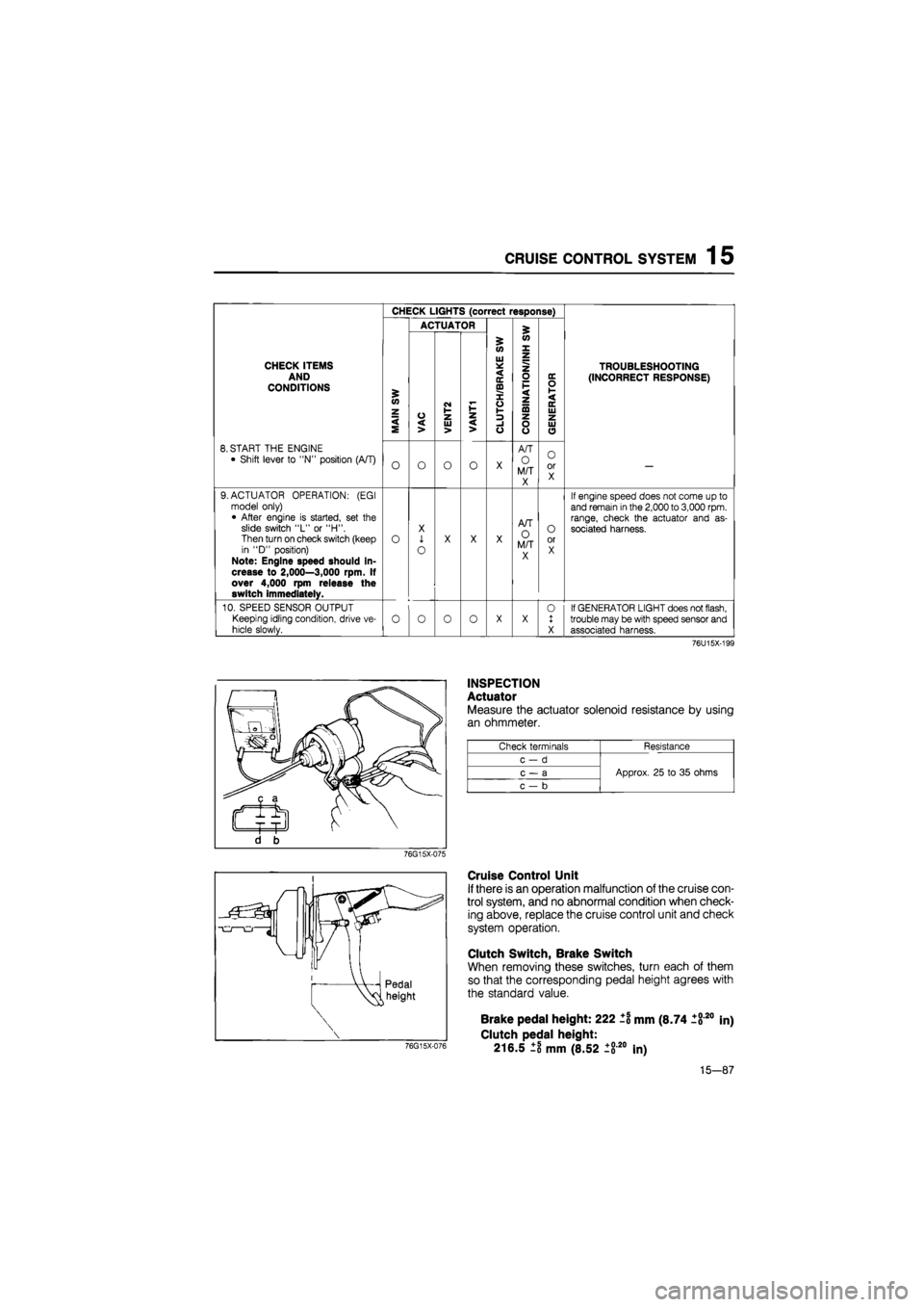
INSPECTION
Actuator
Measure the actuator solenoid resistance by using
an ohmmeter.
Check terminals Resistance
c-d
Approx. 25 to 35 ohms c — a Approx. 25 to 35 ohms
c — b
Approx. 25 to 35 ohms
76G15X-075
Cruise Control Unit
If there is an operation malfunction of the cruise con-
trol system, and no abnormal condition when check-
ing above, replace the cruise control unit and check
system operation.
Clutch Switch, Brake Switch
When removing these switches, turn each of them
so that the corresponding pedal height agrees with
the standard value.
76G15X-076
Brake pedal height: 222 ±1 mm (8.74 1820
Clutch pedal height:
216.5 ±8 mm (8.52 ±820 In)
in)
15-87
1 5 CRUISE CONTROL SYSTEM
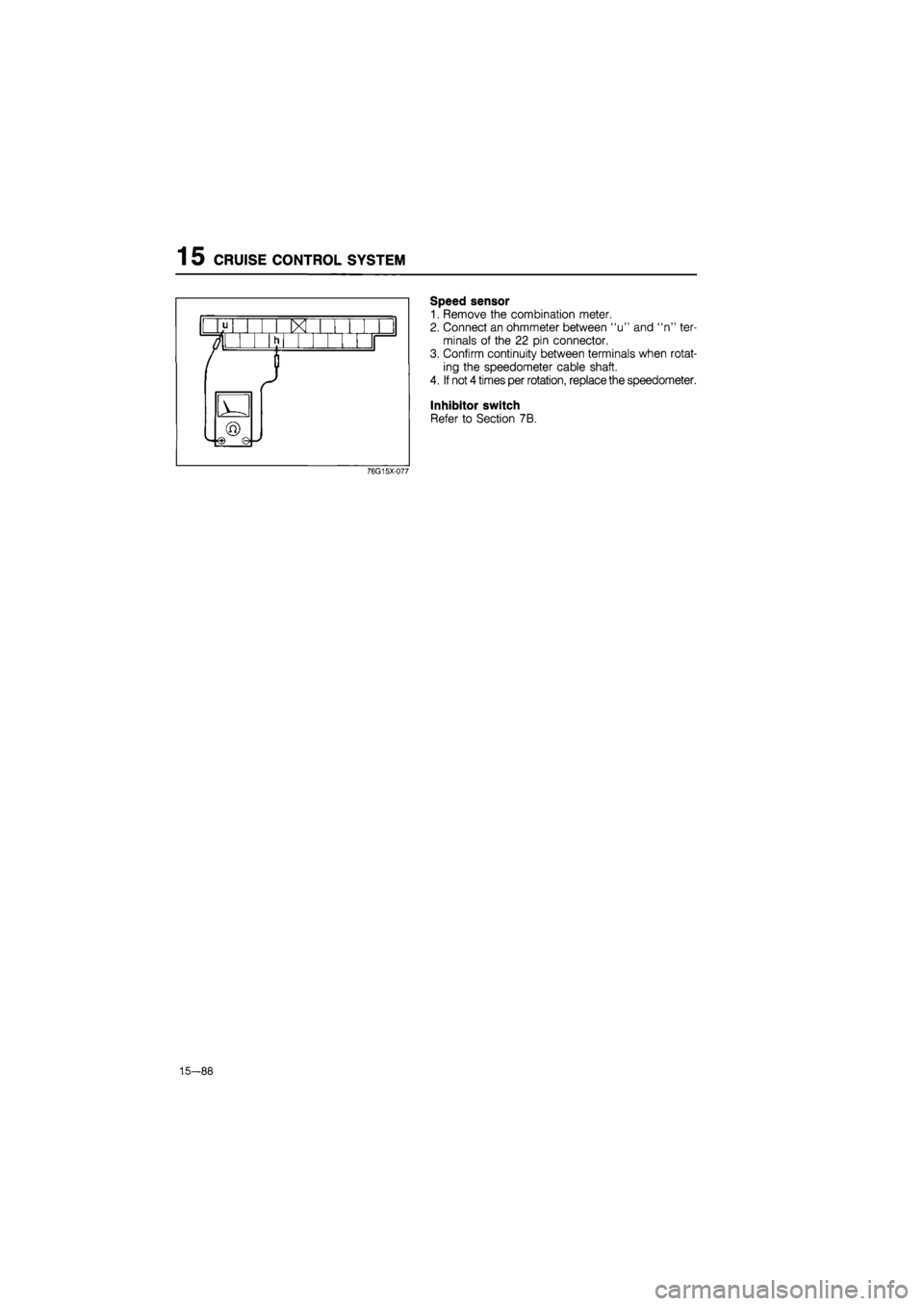
Speed sensor
1. Remove the combination meter.
2. Connect an ohmmeter between "u" and "n" ter-
minals of the 22 pin connector.
3. Confirm continuity between terminals when rotat-
ing the speedometer cable shaft.
4. If not 4 times per rotation, replace the speedometer.
Inhibitor switch
Refer to Section 7B.
76G15X-077
—88

