clock MAZDA 626 1987 Workshop Manual
[x] Cancel search | Manufacturer: MAZDA, Model Year: 1987, Model line: 626, Model: MAZDA 626 1987Pages: 1865, PDF Size: 94.35 MB
Page 14 of 1865

0 PRE-DELIVERY INSPECTION
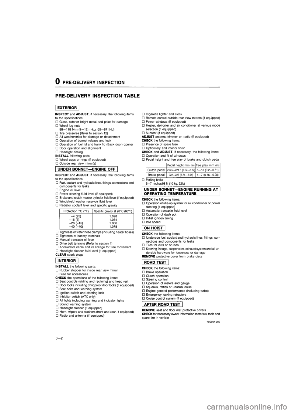
PRE-DELIVERY INSPECTION TABLE
EXTERIOR
INSPECT and ADJUST, if necessary, the following items
to the specifications:
• Glass, exterior bright metal and paint for damage
• Wheel lug nuts
88—118 N m (9—12 m-kg, 65—87 ft-lb)
• Tire pressures (Refer to section 12)
• All weatherstrips for damage or detachment
• Operation of bonnet release and lock
• Operation of fuel lid and trunk lid (Back door) opener
• Door operation and alignment
• Headlight aiming
INSTALL following parts:
• Wheel caps or rings (if equipped)
• Outside rear view mirror(s)
UNDER BONNET—ENGINE OFF
INSPECT and ADJUST, if necessary, the following items
to the specifications:
• Fuel, coolant and hydraulic lines, fittings, connections and
components for leaks
• Engine oil level
• Power steering fluid level (if equipped)
• Brake and clutch master cylinder fluid level (if equipped)
• Windshield washer reservoir fluid level
• Radiator coolant level and specific gravity
Protection °C (°F) Specific gravity at 20°C (68°F)
-4 (25) 1.028
-16(3) 1.054
-26 (-15) 1.066 -40 (-40) 1.078
• Tightness of water hose clamps (including heater hoses)
• Tightness of battery terminals
• Manual transaxle oil level
• Drive belt tensions (Refer to section 1)
• Accelerator cable and its linkage for free movement
• Headlight cleaner fluid level (if equipped)
CLEAN spark plugs
INTERIOR
INSTALL the following parts:
• Rubber stopper for inside rear view mirror
• Fuse for accessories
CHECK the operations of the following items:
• Seat controls (sliding and reclining) and head rest
• Door locks including childproof door locks (if equipped)
• Seat belts and warning system
• Ignition switch and steering lock
• Inhibitor switch (ATX only)
• All lights including warning and indicator lights
• Sound warning system
• Headlight cleaner (if equipped)
• Horn, wipers and washers (front and rear, if equipped)
• Radio and antenna (if equipped)
• Cigarette lighter and clock
• Remote control outside rear view mirrors (if equipped)
• Power windows (if equipped)
• Heater, defroster and air conditioner at various mode
selection (if equipped)
• Sunroof (if equipped)
ADJUST antenna trimmer on radio (if equipped)
CHECK the following items:
• Presence of spare fuse
• Upholstery and interior finish
CHECK and ADJUST, if necessary, the following items:
• Operation and fit of windows
• Pedal height and free play of brake and clutch pedal
Pedal height mm (in) free play mm (in)
Clutch pedal 216.5-221.5 (8.52-8.72) 5-13 (0.2-0.51)
Brake pedal 222-227 (8.74-8.94) 4-7 (0.16-0.28)
• Parking brake
5-7 noches/98 N (10 kg, 22lb)
UNDER BONNET—ENGINE RUNNING AT
OPERATING TEMPERATURE
CHECK the following items:
• Operation of idle-up system for air conditioner or power
steering (if equipped)
• Automatic transaxle fluid level
• Operation of dash pot
• Initial ignition timing
• Idle speed
ON HOIST
CHECK the following items:
• Underside fuel, coolant and hydraulic lines, fittings, con-
nections and components for leaks
• Tires for cuts or bruises
• Steering linkage, suspension, exhaust system and all un-
derside hardware for looseness or damage
REMOVE protective cover from brake discs
ROAD TEST"
CHECK the following items:
• Brake operation
• Clutch operation
• Steering control
• Operation of meters and gauge
• Squeaks, rattles or unusual noise
• Engine general performance (including turbo)
• Emergency locking retractors
• Cruise control system (if equipped)
AFTER ROAD TEST
REMOVE seat and floor mat protective covers
CHECK for necessary owner information materials, tools and
spare tire in vehicle
-76G00X-002
0-2
Page 220 of 1865

1C TUNE-UP PROCEDURE
Comprex supercharger
Deflection mm (in)
New 4 0-6.0 (0.16—0.23)
Used 8.0-10 0 (0 31-0.39)
If necessary, loosen the idler lock nut and adjust
the belt deflection by turning the adjust bolt.
Tightening torque:
16—23 Nm (1.6—2.3 m-kg, 12—17 ft-lb)
76G01C-011
o
INJECTION TIMING
1. Disconnect the negative battery cable.
2. Release the CSD using the screw driver.
3. Remove the cover on the clutch housing.
4. Turn the flywheel and set the indicator at ATDC.
5. Disconnect the injection pipes from the injection
pump.
76G04D-008
6. Remove the hydraulic head plug from the injec-
tion pump.
7. Mount the SST into the plug hole on the hydraulic
head so the tip of the dial gauge pointer touches
the plunger end of the pump and the dial gauge
indicates approx. 2.0 mm (0.08 in).
76G04D-009
8. Turn the crankshaft slowly counterclockwise to
30-50° BTDC.
9. Make sure the dial indicator pointer no longer
moves by slightly turning the crankshaft.
10. Set the dial gauge scale to Zero at the pointer.
76G04D-010
1C-8
Page 221 of 1865

TUNE-UP PROCEDURE 1C
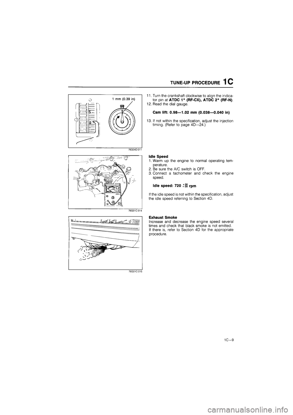
11. Turn the crankshaft clockwise to align the indica-
tor pin at ATDC 1° (RF-CX), ATDC 2° (RF-N)
12. Read the dial gauge.
Cam lift: 0.98—1.02 mm (0.038—0.040 in)
13. If not within the specification, adjust the injection
timing. (Refer to page 4D—24.)
76G04D-011
Idle Speed
1. Warm up the engine to normal operating tem-
perature.
2. Be sure the A/C switch is OFF.
3. Connect a tachometer and check the engine
speed.
Idle speed: 720 ±20 rpm
If the idle speed is not within the specification, adjust
the idle speed referring to Section 4D.
76G01C-014
Exhaust Smoke
Increase and decrease the engine speed several
times and check that black smoke is not emitted.
If there is, refer to Section 4D for the appropriate
procedure.
76G01C-015
1C—9
Page 226 of 1865

ON-VEHICLE MAINTENANCE (TIMING BELT) 1 C
2. Install the timing belt tensioner and spring.
3. Temporarily secure the tensioner with it shifted
outwards.
63G01D-330
4. Install the timing belt.
Caution
a) The timing belt must be reinstalled in the
same direction of previous rotation, if it is
to be reused.
b) Be sure that there is no oil, grease, or dirt
on the timing belt.
76G01C-024
Install the idler pulley.
Tightening torque:
37—52
N
m (3.8—5.3 m-kg, 27-38 ft-lb)
Remove the affixing bolts from the injection pulley.
76G01C-025
7. Loosen the tensioner lock bolt.
8. Turn the crankshaft twice in the direction of rota-
tion (clockwise).
Caution
Do not rotate reverse direction.
9. Check that each timing mark is correcty aligned.
If not aligned, remove the timing belt. Repeat step
1-8.
76G01C-030
1C-14
Page 237 of 1865

ON-VEHICLE MAINTENANCE (VALVE SEAL) 1 C
Removal note
Camshaft pulley
1. After removing the timing belt, turn the crankshaft
45° clockwise.
76G01C-054
2. Hold the camshaft with a wrench (29 mm, 1.14 in)
and loosen the camshaft pulley lock bolt.
Caution
Do not damage the cylinder head edge with
the wrench.
4BG01B-044
3. Separate the camshaft pulley from the camshaft
with the SST.
Caution
Do not hit the camshaft pulley with a hammer.
Rear camshaft pulley
Remove the rear camshaft pulley in the same man-
ner used for camshaft pulley.
76G01C-055
Camshaft cap
Loosen the camshaft nuts in two or three steps in the
order shown in the figure.
76G01C-066
1C—25
Page 296 of 1865

1C ASSEMBLY (TIMING BELT)
jf^iLJF'
76G01C-194
Timing marks
Timing marks
76G01C-195
76G01C-196
4. Install the idler pulley.
Tightening torque:
37—52 N
m
(3.8—5.3 m-kg, 27—38 ft-lb)
5. Remove the two affixing bolts from the injection
pump pulley.
6. Loosen the tensioner lock bolt.
7. Turn the crankshaft twice in the direction of rota-
tion (clockwise).
Caution
Do not rotate in reverse direction.
8. Check that each timing mark is correctly aligned.
If not aligned, remove the timing belt. Repeat step
2-9.
9. Tighten the timing belt tensioner lock bolt.
Tightening torque:
37—52
N m
(3.8—5.3 m-kg, 27—38 ft-lb)
10. Check the timing belt tension.
If the tension is not correct, loosen the tensioner
lock bolt and repeat step 6—9, or replace the ten-
sioner spring.
Standard deflection:
9.0—11.5 mm (0.35—0.45 in)
/98 N (10 kg, 22 lb)
Caution
Be sure not to apply tension other than that
of the tensioner spring.
76G01C-197
1C-84
Page 558 of 1865

4B CONTROL SYSTEM
y
/OTaWX 1
rx
Throttle stop screw
76G04B-117
76G04B-11E
Counter clockwise i i
Clockwise
76G04B-119
3. Place a feeler gauge between the lever and the
throttle stop screw and check that the SST buzz-
er sounds or that there is continuity between ter-
minals B and D.
Feeler gauge 0 mm (0 in) 0.7 mm (0.028 in)
Buzzer Sounds Does not sound
Lamp ON OFF
Continuity YES NO
4. If not correct, adjust the throttle sensor as outlined
below.
Adjustment
1. Disconnect the connector and connect the SST
to the throttle sensor.
2. Place a 0.40 mm (0.016 in) feeler gauge between
the lever and the throttle stop screw.
3. Loosen the two attaching screws.
4. Rotate the throttle sensor clockwise about 30°, then
rotate it counterclockwise until the buzzer sounds.
5. If it does not buzz, replace the throttle sensor.
6. If it does buzz, substitute the feeler gauge with a
0.55 mm (0.022 in) gauge
7. Check that the buzzer does not sound.
8. If it buzzes, repeat steps 3 to 7.
If it still buzzes, replace the throttle sensor.
9. Tighten the two attaching screws.
Note
Be careful not to disturb the throttle sensor
position when tightening the screws.
10. Open the throttle valve fully a few times; then
recheck the adjustment of the throttle sensor.
11. Disconnect the SST from the throttle sensor and
reconnect the connector.
76G04B-120
4B-96
Page 673 of 1865

4D OUTLINE
OUTLINE
The Mazda 626 offers two diesel engines; a Comprex supercharged RF-CX engine, and a normally
aspirated RF-N engine.
SPECIFICATIONS
—Engine model
Item ———
ECE UK, GENERAL —Engine model
Item ——— RF-CX RF-N
Fuel tank Capacity liters (US gal, Imp gal) 60 (15.9, 13.2)
Fuel filter Type Cartridge, paper element
Sedimenter Type With detector
Injection pump
Type Bosch VE distributor
Injection pump
Manufacturer Diesel Kiki Co,, Ltd.
Injection pump
Direction of rotation Clockwise Injection pump
Drive method Timing belt
Injection pump
Plunger diameter mm (in) 9.0 (0.35) 8.0 (0.31)
Injection pump
Cam lift mm (in) 2.2 (0.087)
Injection nozzle Type Throttle Injection nozzle
Injection pressure kPa (kg/cm2, psi) 13,240 (135 , 1,920)
Injection timing ATDC
1
° TDC 0°
Idle speed rpm 720 _+f0
Fast idle speed (A/C ON) rpm 700-750
Cold start device Engine speed rpm 1.100 Cold start device
Advance degree 6°
Air cleaner Type Cartridge, paper element Air cleaner Type
Wet Dry
PCV system Type Open Closed
76G04D-002
4D—2
Page 676 of 1865

ON-VEHICLE MAINTENANCE 4D
INJECTION TIMING
1. Disconnect the negative battery cable.
2. Release the CSD using the screw driver.
3. Remove the cover on the clutch housing.
4. Turn the flywheel and set the indicator at TDC.
5. Disconnect the injection pipes from the injection
pump.
76G04D-008
6. Remove the hydraulic head plug from the injec-
tion pump.
7. Mount the SST into the plug hole on the hydraulic
head so the tip of the dial gauge pointer touches
the plunger end of the pump and the dial gauge
indicates approx. 2.0 mm (0.08 in).
76.G04D-009
8. Turn the crankshaft slowly counterclockwise to
30—50° BTDC.
9. Make sure the dial indicator pointer no longer
moves by slightly turning the crankshaft.
10. Set the dial gauge scale to Zero at the pointer.
76G04D-010
11. Turn the crankshaft clockwise to align the indica-
tor pin at ATDC 1° (RF-CX), TDC 0° (RF-N).
12. Read the dial gauge.
Cam lift: 0.98—1.02 mm (0.038—0.040 in)
13. If not within the specification, adjust the injection
timing. (Refer to page 4D—24.)
76G04D-011
4D-5
Page 696 of 1865

FUEL SYSTEM 4D
RF-CX
o
M
o
10-
RF-N
M
m
M
o TO"
5-
76G04D-059
76G04D-060
76G04D-061
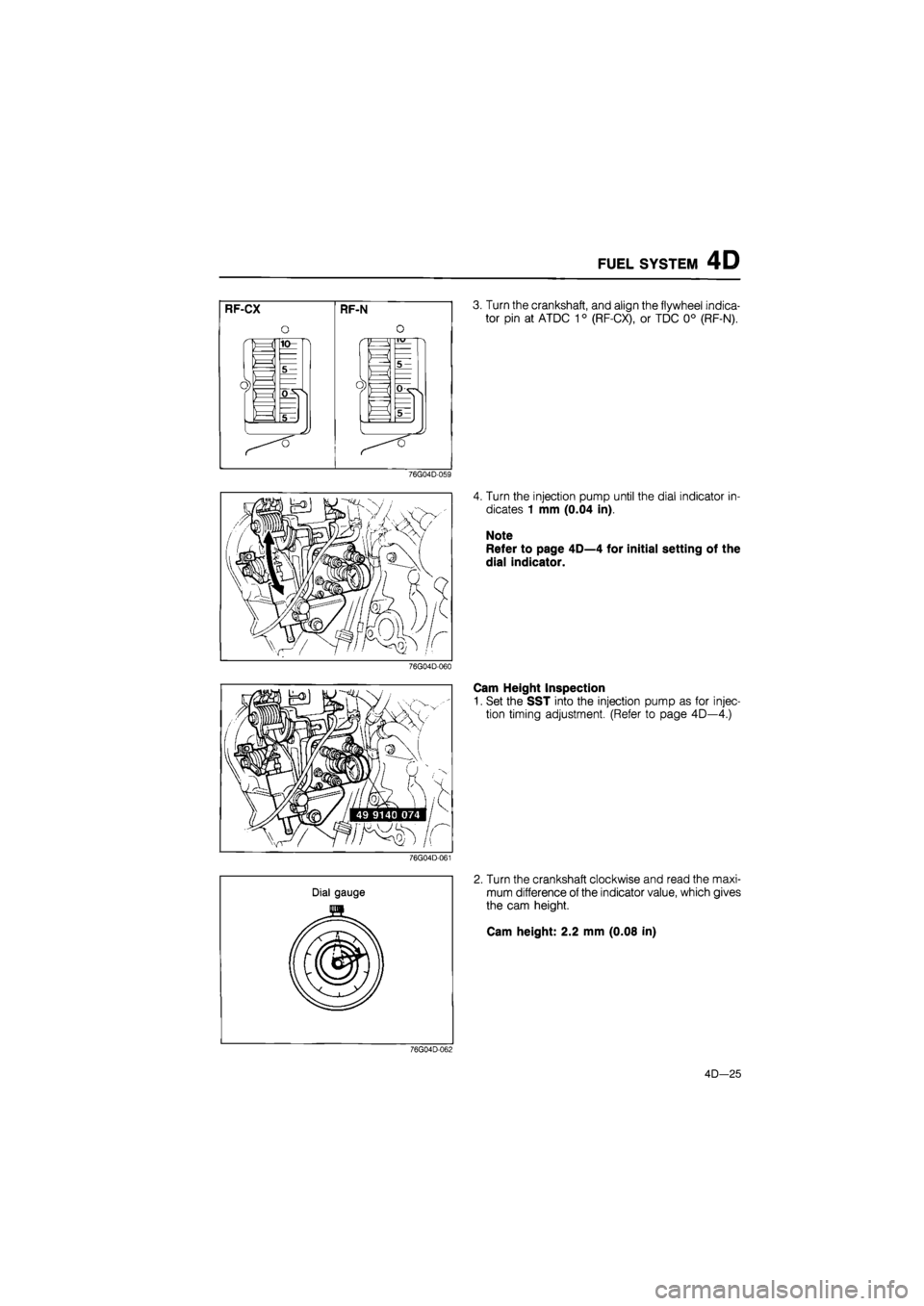
3. Turn the crankshaft, and align the flywheel indica-
tor pin at ATDC 10 (RF-CX), or TDC 0° (RF-N).
4. Turn the injection pump until the dial indicator in-
dicates 1 mm (0.04 in).
Note
Refer to page 4D—4 for initial setting of the
dial indicator.
Cam Height Inspection
1. Set the SST into the injection pump as for injec-
tion timing adjustment. (Refer to page 4D—4.)
2. Turn the crankshaft clockwise and read the maxi-
mum difference of the indicator value, which gives
the cam height.
Cam height: 2.2 mm (0.08 in)
76G04D-062
4D—25