sensor MAZDA 626 1987 Owner's Manual
[x] Cancel search | Manufacturer: MAZDA, Model Year: 1987, Model line: 626, Model: MAZDA 626 1987Pages: 1865, PDF Size: 94.35 MB
Page 497 of 1865

IDLE-UP SYSTEM 4B
IDLE-UP SYSTEM
Dynamic chamber
To engine i
lN
Water thermo |ntake air sensor thermo
sensor
E/L control unit
-D
Solenoid A
From air ^^ flow meter ~
Engine
control
unit
Atmospheric pressure sensor
HI
f
"Solenoid B
UJ m
Solenoid C
u
Adjusting screw
| A/C
H-!
relay
IGN switch
-©n
To engine
control
unit
Magnetic clutch
fftf
tr Main relay
r © ©
P/S pressure switch
76G04B-043
Air Valve
This valve is constructed so that the gate valve is opened and closed by means of a bimetal strip and
heat coil. It acts as a fast idle mechanism by opening the gate valve to increase intake air by bypass-
ing the throttle valve while engine is cold, therefore engine speed is increased to shorten the warm
up period.
Air Bypass Solenoid Valve
This valve incorporates three solenoid valves. They operate according to the signal from the engine
control unit or A/C switch in order to achieve idling stability and the optimum idle speed.
The operating conditions of each solenoid valve are as shown below.
Solenoid valve Operating condition
A A/C operated
B Intake air temp, above 55°C (131 °F)
or
vehicle
at
above 1,000
m
(3,280
ft)
C P/S operated, E/L applied, intake
air
temp, above 55°C (131 °F), pressure regulator solenoid ON
or
vehicle
at
above 1,900
m
(6,232
ft)
4B-35
Page 498 of 1865

4B IDLE-UP SYSTEM
COMPONENT DESCRIPTIONS
Component Function Remarks
Air bypass solenoid
valve
Controls bypass
air
amount Operates A: A/C
: ON
B: Intake
air
temp, high
or at
high
al-
titude C: P/S
:
ON, E/L applied
or
hot start
Air valve
When cold, supplies bypass
air
into
dy-
namic chamber
• Engine speed increased
to
shorten
warm-up period
• Bimetal type
Atmospheric pressure sensor
Detects atmospheric pressure; sends sig-
nal
to
engine control unit
E/L control unit
Detects electrical load applied; sends sig-nal
to
engine control unit
Engine control unit
Detects signals from input sensors and switches; controls
air
bypass solenoid valve
Intake air thermo sensor
Detects intake
air
temperature; sends sig-
nal
to
engine control unit
Installed
in air
flow meter
P/S pressure switch
Detects P/S operation; sends signal
to
engine control unit P/S:
ON
when steering wheel turnefl right
or
left
76g04b-044
4B-36
Page 499 of 1865

IDLE-UP SYSTEM 4B
TROUBLESHOOTING
Check the condition of the wiring harness and connectors before checking the sensors or switch.
Possible
cause
\ Page
Symptom
Air valve
Air bypass solenoid valve Engine control unit
terminal
Possible
cause
\ Page
Symptom
Air valve
Idle-up singal Adjustment
Engine control unit
terminal
Possible
cause
\ Page
Symptom
Air valve
Idle-up singal Adjustment
1S 20
Possible
cause
\ Page
Symptom 4B—38 4B—39 4B—40 4B—89 4B—90
Engine
stalls
While warming up
1 2 3 4 5
Engine
stalls After warming up
1 2 3 4
Rough Idle
While warming up
1 2 3 4 5
Rough Idle After warming up
1 2 3 4
High idle speed after warming up
1 2 3 4 5
Runs rough on deceleration
1 2 3 4
Afterburn in exhaust system
1 2 3 4 5
Fails emission test
1 2 3 4 5
76G04B-045
4B-37
Page 501 of 1865
IDLE-UP SYSTEM 4B
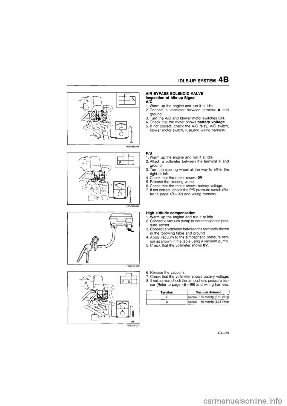
AIR BYPASS SOLENOID VALVE
Inspection of Idle-up Signal
A/C
1. Warm up the engine and run it at idle.
2. Connect a voltmeter between terminal A and
ground.
3. Turn the A/C and blower motor switches ON.
4. Check that the meter shows battery voltage.
5. If not correct, check the A/C relay, A/C switch,
blower motor switch, fuse,and wiring harness.
76G04B-048
P/S
1. Warm up the engine and run it at idle.
2. Attach a voltmeter between the terminal F and
ground.
3. Turn the steering wheel all the way to either the
right or left.
4. Check that the meter shows OV.
5. Release the steering wheel.
6. Check that the meter shows battery voltage.
7. If not correct, check the P/S pressure switch (Re-
fer to page 4B—92) and wiring harness.
76G04B-049
High altitude compensation
1. Warm up the engine and run it at idle.
2. Connect a vacuum pump to the atmospheric pres-
sure sensor.
3. Connect a voltmeter between the terminals shown
in the following table and ground.
4. Apply vacuum to the atmospheric pressure sen-
sor as shown in the table using a vacuum pump.
5. Check that the voltmeter shows OV.
76G04B-050
J
O
6. Release the vacuum.
7. Check that the voltmeter shows battery voltage.
8. If not correct, check the atmospheric pressure sen-
sor (Refer to page 4B—99) and wiring harness.
Terminal Vacuum Amount
F Approx. 155 mmHg (6.10 inHg)
D Approx.
85
mmHg (3.35 inHg)
76G04B-051
4B-39
Page 502 of 1865
4B IDLE-UP SYSTEM
76G04B-052
76G04B-053
76G04B-054
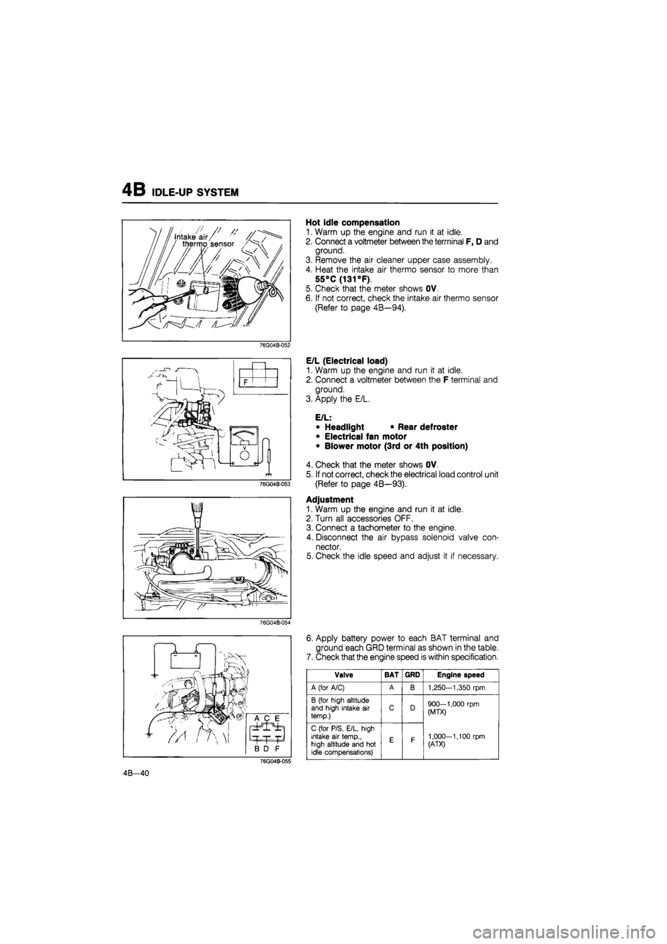
Hot idle compensation
1. Warm up the engine and run it at idle.
2. Connect a voltmeter between the terminal F, D and
ground.
3. Remove the air cleaner upper case assembly.
4. Heat the intake air thermo sensor to more than
55°C
(131
°F).
5. Check that the meter shows OV.
6. If not correct, check the intake air thermo sensor
(Refer to page 4B—94).
E/L (Electrical load)
1. Warm up the engine and run it at idle.
2. Connect a voltmeter between the F terminal and
ground.
3. Apply the E/L.
E/L:
• Headlight • Rear defroster
• Electrical fan motor
• Blower motor (3rd or 4th position)
4. Check that the meter shows OV.
5. If not correct, check the electrical load control unit
(Refer to page 4B—93).
Adjustment
1. Warm up the engine and run it at idle.
2. Turn all accessories OFF.
3. Connect a tachometer to the engine.
4. Disconnect the air bypass solenoid valve con-
nector.
5. Check the idle speed and adjust it if necessary.
6. Apply battery power to each BAT terminal and
ground each GRD terminal as shown in the table.
7. Check that the engine speed is within specification.
76G04B-055
Valve BAT GRD Engine speed
A (for A/C) A B 1,250—1,350
rpm
B (for high altitude and high intake
air
temp.) C D 900—1,000
rpm
(MTX)
1,000-1,100
rpm
(ATX)
C (for P/S, E/L, high intake
air
temp., high altitude and
hot
idle compensations)
E F
900—1,000
rpm
(MTX)
1,000-1,100
rpm
(ATX)
4B—40
Page 505 of 1865
FUEL SYSTEM 4B
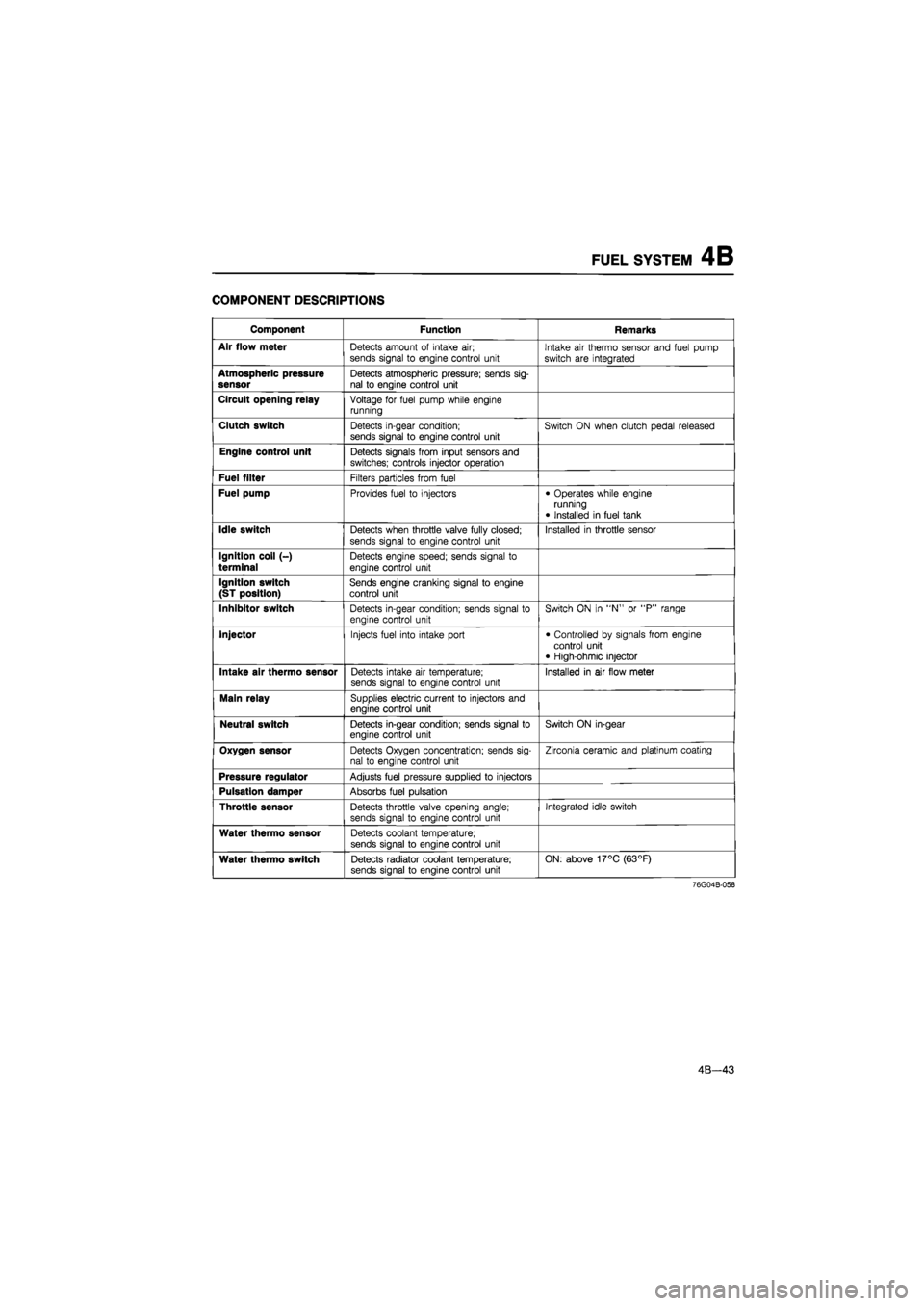
COMPONENT DESCRIPTIONS
Component Function Remarks
Air flow meter
Detects amount
of
intake
air;
sends signal
to
engine control unit Intake
air
thermo sensor and fuel pump
switch
are
integrated
Atmospheric pressure sensor
Detects atmospheric pressure; sends sig-nal
to
engine control unit
Circuit opening relay
Voltage
for
fuel pump while engine running
Clutch switch
Detects in-gear condition; sends signal
to
engine control unit Switch
ON
when clutch pedal released
Engine control unit
Detects signals from input sensors and switches; controls injector operation
Fuel filter
Filters particles from fuel
Fuel pump
Provides fuel
to
injectors • Operates while engine running
• Installed
in
fuel tank
Idle switch
Detects when throttle valve fully closed;
sends signal
to
engine control unit
Installed
in
throttle sensor
Ignition coil (-) terminal
Detects engine speed; sends signal
to
engine control unit
Ignition switch (ST position)
Sends engine cranking signal
to
engine control unit
Inhibitor switch
Detects in-gear condition; sends signal
to
engine control unit
Switch
ON in "N" or "P"
range
Injector
Injects fuel into intake port • Controlled
by
signals from engine control unit • High-ohmic injector
Intake air thermo sensor
Detects intake
air
temperature;
sends signal
to
engine control unit Installed
in air
flow meter
Main relay
Supplies electric current
to
injectors and engine control unit
Neutral switch
Detects in-gear condition; sends signal
to
engine control unit
Switch
ON
in-gear
Oxygen sensor
Detects Oxygen concentration; sends sig-nal
to
engine control unit
Zirconia ceramic and platinum coating
Pressure regulator
Adjusts fuel pressure supplied
to
injectors
Pulsation damper
Absorbs fuel pulsation
Throttle sensor
Detects throttle valve opening angle; sends signal
to
engine control unit
Integrated idle switch
Water thermo sensor
Detects coolant temperature;
sends signal
to
engine control unit
Water thermo switch
Detects radiator coolant temperature; sends signal
to
engine control unit ON: above 17°C (63°F)
76G04B-058
4B—43
Page 506 of 1865
4B FUEL SYSTEM
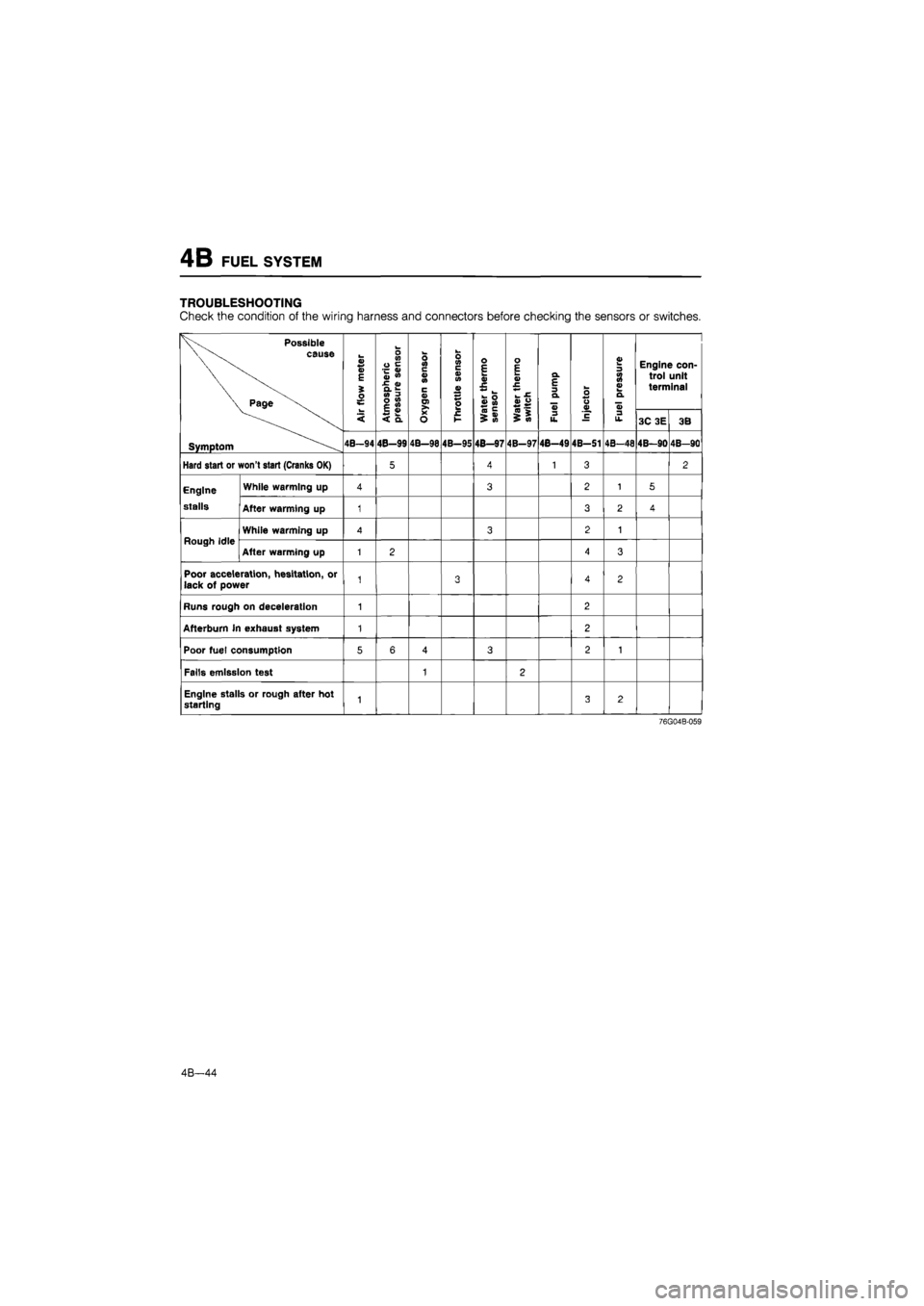
TROUBLESHOOTING
Check
the
condition
of
the wiring harness and connectors before checking
the
sensors
or
switches.
Possible
cause
Page
V
S E
i
o
o V)
0
e
~
0)
Ju
»
•E
<»
CL
01
3
0
<0
1
£
Oxygen
sensor
s c V
in
V
P
o E k_
•E **
l_
h
O
v
w
Water
thermo
switch
Q.
E
3 Q.
u
Injector
£ 3 3 o d
aj
Engine
con-
trol unit terminal
< £
8
<
Q. Oxygen
sensor
£ t->
0)
>
M Water
thermo
switch
3
u.
Injector
3
u. 3C
3E
3B
Symptom 4B-94 4B-99 4B—98 4B-95 48—97 4B-97 4B-49 4B-S1 4B-48 4B-90 4B-90
Hard start
or
won't start (Cranks
OK)
5 4 1 3 2
Engine While warming
up
4 3 2 1 5
stalls After warming
up
1 3 2 4
Rough Idle While warming
up
4 3 2 1
Rough Idle After warming
up
1 2 4 3
Poor acceleration, hesitation,
or
lack
of
power
1 3 4 2
Runs rough
on
deceleration
1 2
Afterburn
in
exhaust system
1 2
Poor fuel consumption
5 6 4 3 2 1
Falls emission test
1 2
Engine stalls
or
rough after
hot
starting
1 3 2
76G04B-059
4B—44
Page 515 of 1865
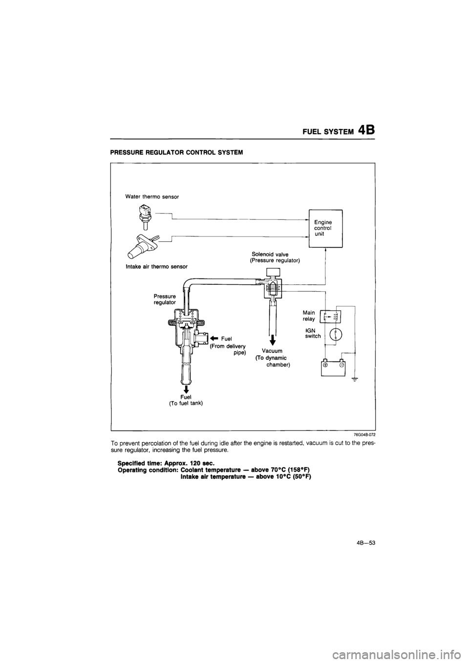
FUEL SYSTEM 4B
PRESSURE REGULATOR CONTROL SYSTEM
Water thermo sensor
*
Fuel
(To fuel tank)
76G04B-072
To prevent percolation of the fuel during idle after the engine is restarted, vacuum is cut to the pres-
sure regulator, increasing the fuel pressure.
Specified time: Approx. 120 sec.
Operating condition: Coolant temperature — above 70°C (158°F)
Intake air temperature — above 10°C (50°F)
4B—53
Page 516 of 1865
4B FUEL SYSTEM
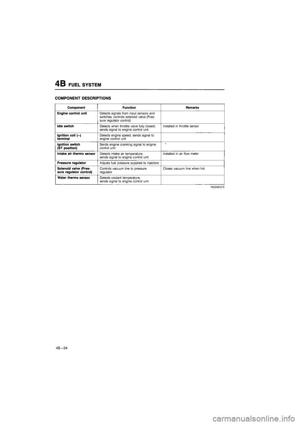
COMPONENT DESCRIPTIONS
Component Function Remarks
Engine control unit Detects signals from input sensors and
switches; controls solenoid valve (Pres-
sure regulator control)
Idle switch Detects when throttle valve fully closed; sends signal to engine control unit Installed in throttle sensor
Ignition coil (-) terminal Detects engine speed; sends signal to engine control unit
Ignition switch
(ST position)
Sends engine cranking signal to engine control unit
Intake air thermo sensor Detects intake air temperature; sends signal to engine control unit
Installed in air flow meter
Pressure regulator Adjusts fuel pressure supplied to injectors
Solenoid valve (Pres-sure regulator control) Controls vacuum line to pressure regulator Closes vacuum line when hot
Water thermo sensor Detects coolant temperature; sends signal to engine control unit
76G04B-073
4B—54
Page 517 of 1865
FUEL SYSTEM 4B
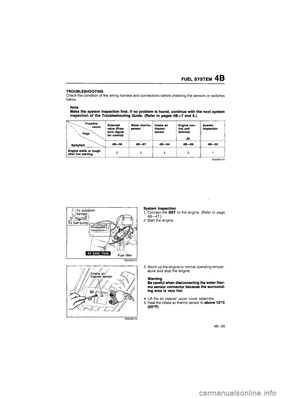
TROUBLESHOOTING
Check the condition of the wiring harness and connections before checking the sensors or switches
below.
Note
Make the system inspection first. If no problem is found, continue with the next system
inspection of the Troubleshooting Guide. (Refer to pages 4B—7 and 8.)
Possible \ cause
\ Page
Solenoid valve (Pres-sure regula-tor control)
Water thermo
sensor Intake air
thermo sensor
Engine con-trol unit terminal
2K
System inspection
Symptom 4B—56 4B—97 4B—94 4B—89 4B—55
Engine stalls or rough after hot starting 2 3
A
5 1
76G04B-074
System Inspection
1. Connect the SST to the engine. (Refer to page
4B—47.)
2. Start the engine.
76G04B-075
3. Warm up the engine to normal operating temper-
ature and stop the engine.
Warning
Be careful when disconnecting the water ther-
mo sensor connector because the surround-
ing area is very hot.
4. Lift the air cleaner upper cover assembly.
5. Heat the intake air thermo sensor to above 10°C
(50 °F).
76G04B-076
4B—55