seat adjustment MAZDA 626 1987 Workshop Manual
[x] Cancel search | Manufacturer: MAZDA, Model Year: 1987, Model line: 626, Model: MAZDA 626 1987Pages: 1865, PDF Size: 94.35 MB
Page 20 of 1865

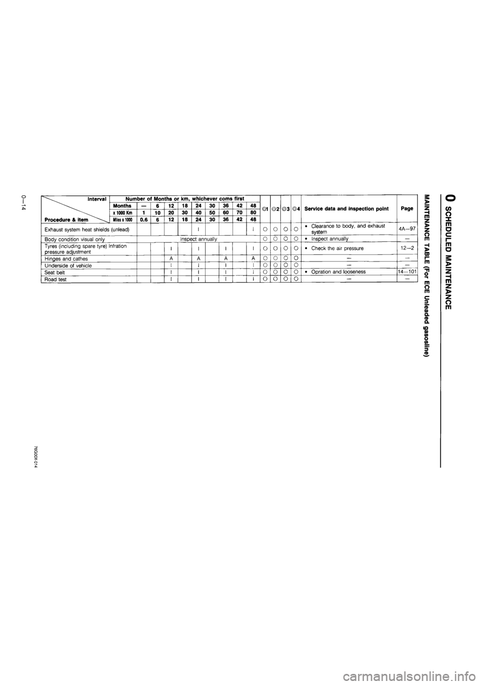
0 1 00 Interval
Procedure & item
Number of Months or km, whichever corns first
©1 ©2 ©3 ©4 Service data and inspection point Page
Interval
Procedure & item
Months — 6 12 18 24 30 36 42 48 ©1 ©2 ©3 ©4 Service data and inspection point Page
Interval
Procedure & item
x 1000 Km
1 10 20 30 40 50 60 70 80 ©1 ©2 ©3 ©4 Service data and inspection point Page
Interval
Procedure & item
Miles x 1000
0.6 6 12 18 24 30 36 42 48
©1 ©2 ©3 ©4 Service data and inspection point Page
Brake lines, Hoses, and connections I I I I O O O O • Proper attachment and connections 11-8
Body condition Inspect annually O O o O -—
Tyres (including spare tyre) Infration pressure adjustment I I I I o O o o • Check the air pressure 12-2
Hinges and cathes A A A A o O o o — —
Underside of vehicle I I I I 0 0 o o — —
Seat belt I I I I o o o o • Opration and looseness 14-101
Road test I I I I o o o o — —
o o o X o o 00
Page 26 of 1865

o Interval Number of Months or km, whichever corns first
Months — 6 12 18 24 30 36 42 48 ©1 ©2 ©3 ©4 Service data and inspection point Page x 1000
Km
1 10 20 30 40 50 60 70 80 ©1 ©2 ©3 ©4 Service data and inspection point Page
Procedure & item Miles
x
1000 0.6 6 12 18 24 30 36 42 48
Exhaust system heat shields (unlead) I I O O O O • Clearance to body, and exhaust
system 4A-97
Body condition visual only Inspect annually o o O O • Inspect annually —
Tyres (including spare tyre) Infration
pressure adjustment I I I I o o o O • Check the air pressure 12-2
Hinges and cathes A A A A o o o O — —
Underside of vehicle I I I I o o o o — —
Seat belt I I I I o o o o • Opration and looseness 14—101
Road test I I I I o o o o — —
•>1
Page 397 of 1865

4A FUEL SYSTEM
76G04A-037
Float Level
Caution
This adjustment must be made without the
gasket on the air horn.
1. Turn the air horn upside-down and allow the float
to lower by its own weight.
2. Measure clearance H between the float and the
air horn.
Clearance H: 12.5 mm (0.49 in)
3. If not as specified, bend the float seat lip A to adjust.
4. Turn the air horn to the normal position and allow
the float to lower by its own weight.
5. Measure clearance L between the bottom of the
float and the air horn.
Clearance L: 44 mm (1.73 in)
6. If not as specified, bend the float stop B to adjust.
76G04A-038
76G04A-039
Fast Opening
F6 and FE 8Valve (Except General)
1. With the choke valve fully closed, measure the
clearance between the primary throttle valve and
the wall of the throttle bore.
Specification:
Engine Spec. Clearance mm (in)
F6 General and
Singapore 1.40—1.76
(0.055-0.069) FE 8Valve Middle East and
Unleaded Fuel
1.40—1.76
(0.055-0.069)
2. If not within specification, carefully bend the con-
necting rod to adjust.
4A—32
Page 1552 of 1865

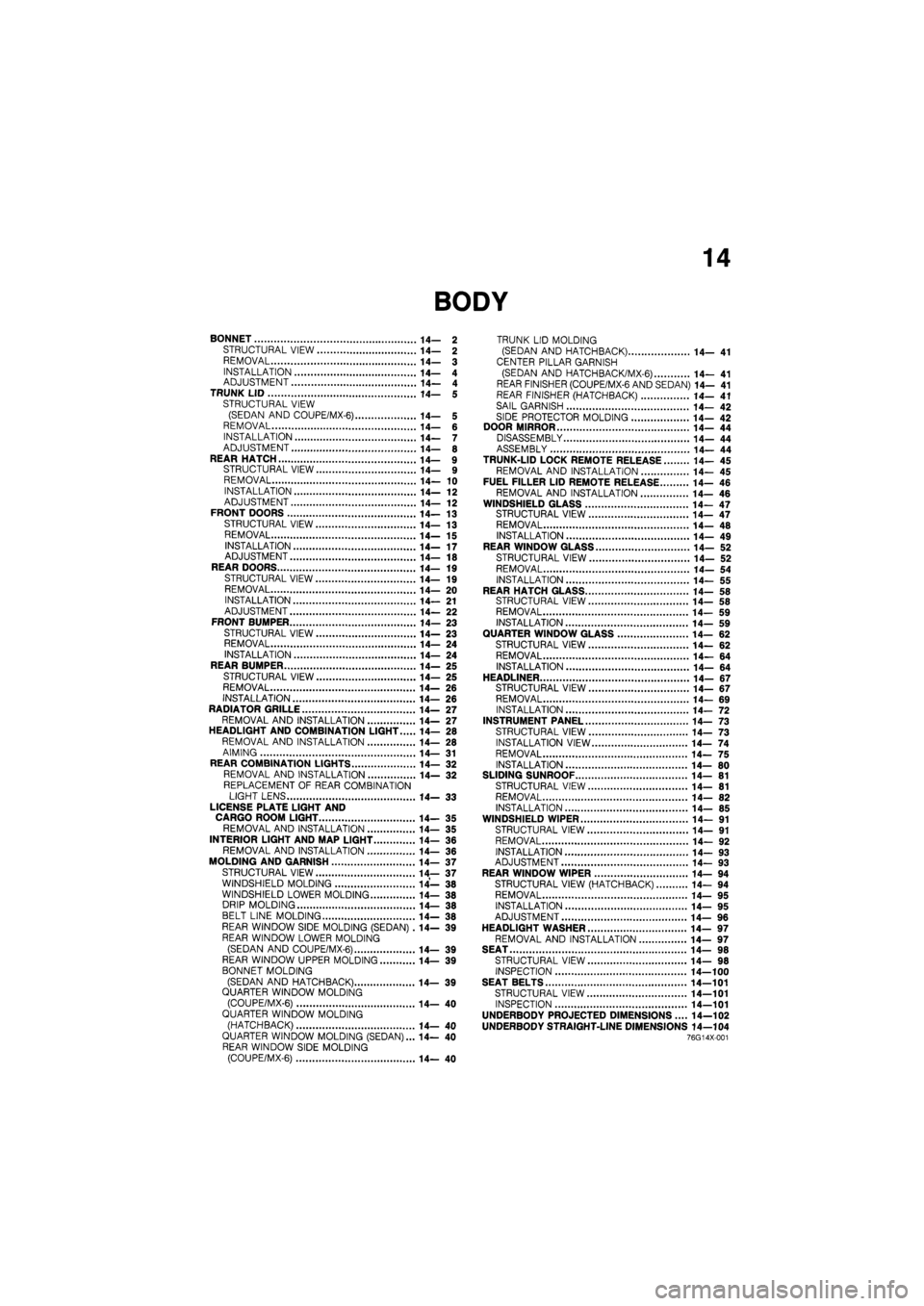
14
BONNET 14— 2
STRUCTURAL VIEW 14— 2
REMOVAL 14— 3
INSTALLATION 14— 4 ADJUSTMENT 14— 4 TRUNK LID 14— 5 STRUCTURAL VIEW (SEDAN AND COUPE/MX-6) 14— 5 REMOVAL 14— 6 INSTALLATION 14— 7 ADJUSTMENT 14— 8
REAR HATCH 14— 9 STRUCTURAL VIEW 14— 9 REMOVAL 14— 10 INSTALLATION 14— 12 ADJUSTMENT 14— 12 FRONT DOORS 14—13
STRUCTURAL VIEW 14— 13
REMOVAL 14—15
INSTALLATION 14—17 ADJUSTMENT 14— 18 REAR DOORS 14—19 STRUCTURAL VIEW 14— 19 REMOVAL 14— 20
INSTALLATION 14— 21 ADJUSTMENT 14— 22 FRONT BUMPER 14— 23
STRUCTURAL VIEW 14—23 REMOVAL 14— 24 INSTALLATION 14—24 REAR BUMPER 14— 25
STRUCTURAL VIEW 14— 25 REMOVAL 14— 26
INSTALLATION 14— 26 RADIATOR GRILLE 14— 27 REMOVAL AND INSTALLATION 14— 27 HEADLIGHT AND COMBINATION LIGHT 14— 28 REMOVAL AND INSTALLATION 14— 28
AIMING 14— 31 REAR COMBINATION LIGHTS 14— 32 REMOVAL AND INSTALLATION 14— 32
REPLACEMENT OF REAR COMBINATION LIGHT LENS 14— 33
LICENSE PLATE LIGHT AND CARGO ROOM LIGHT 14— 35 REMOVAL AND INSTALLATION 14— 35
INTERIOR LIGHT AND MAP LIGHT 14- 36 REMOVAL AND INSTALLATION 14— 36
MOLDING AND GARNISH 14— 37
STRUCTURAL VIEW 14— 37 WINDSHIELD MOLDING 14— 38 WINDSHIELD LOWER MOLDING 14— 38 DRIP MOLDING 14— 38 BELT LINE MOLDING 14— 38 REAR WINDOW SIDE MOLDING (SEDAN) .14— 39 REAR WINDOW LOWER MOLDING
(SEDAN AND COUPE/MX-6) 14— 39 REAR WINDOW UPPER MOLDING 14— 39
BONNET MOLDING
(SEDAN AND HATCHBACK) 14— 39 QUARTER WINDOW MOLDING (COUPE/MX-6) 14— 40 QUARTER WINDOW MOLDING
(HATCHBACK) 14—40 QUARTER WINDOW MOLDING (SEDAN)... 14— 40 REAR WINDOW SIDE MOLDING (COUPE/MX-6) 14— 40
TRUNK LID MOLDING (SEDAN AND HATCHBACK) 14— 41
CENTER PILLAR GARNISH
(SEDAN AND HATCH BAC K/MX-6) 14— 41 REAR FINISHER (COUPE/MX-6 AND SEDAN) 14— 41 REAR FINISHER (HATCHBACK) 14— 41
SAIL GARNISH 14— 42
SIDE PROTECTOR MOLDING 14— 42 DOOR MIRROR 14— 44 DISASSEMBLY 14— 44 ASSEMBLY 14— 44 TRUNK-LID LOCK REMOTE RELEASE 14— 45 REMOVAL AND INSTALLATION 14— 45 FUEL FILLER LID REMOTE RELEASE 14— 46
REMOVAL AND INSTALLATION 14— 46 WINDSHIELD GLASS 14—47 STRUCTURAL VIEW 14—47 REMOVAL 14— 48 INSTALLATION 14— 49 REAR WINDOW GLASS 14— 52
STRUCTURAL VIEW 14— 52 REMOVAL 14— 54
INSTALLATION 14— 55 REAR HATCH GLASS 14— 58 STRUCTURAL VIEW 14— 58 REMOVAL 14— 59 INSTALLATION 14— 59 QUARTER WINDOW GLASS 14— 62 STRUCTURAL VIEW 14— 62
REMOVAL 14— 64 INSTALLATION 14—64
HEADLINER 14- 67 STRUCTURAL VIEW 14—67 REMOVAL 14— 69 INSTALLATION 14— 72 INSTRUMENT PANEL 14— 73 STRUCTURAL VIEW 14— 73
INSTALLATION VIEW 14— 74
REMOVAL 14— 75 INSTALLATION 14— 80 SLIDING SUNROOF 14— 81 STRUCTURAL VIEW 14— 81 REMOVAL 14— 82 INSTALLATION 14— 85 WINDSHIELD WIPER 14— 91
STRUCTURAL VIEW 14— 91
REMOVAL 14— 92
INSTALLATION 14— 93 ADJUSTMENT 14— 93 REAR WINDOW WIPER 14—94 STRUCTURAL VIEW (HATCHBACK) 14— 94 REMOVAL 14— 95 INSTALLATION 14—95 ADJUSTMENT 14— 96
HEADLIGHT WASHER 14— 97 REMOVAL AND INSTALLATION 14— 97 SEAT 14— 98 STRUCTURAL VIEW 14— 98 INSPECTION 14—100 SEAT BELTS 14—101
STRUCTURAL VIEW 14—101 INSPECTION 14—101
UNDERBODY PROJECTED DIMENSIONS.... 14—102 UNDERBODY STRAIGHT-LINE DIMENSIONS 14—104 76G14X-001