MAZDA MX-5 1994 Workshop Manual
Manufacturer: MAZDA, Model Year: 1994, Model line: MX-5, Model: MAZDA MX-5 1994Pages: 1708, PDF Size: 82.34 MB
Page 151 of 1708
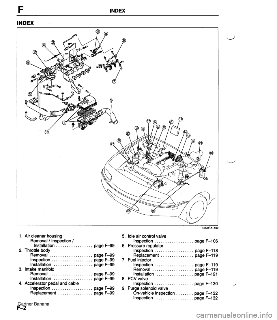
INDEX INDEX 1. Air cleaner housing 5. Idle air control valve Removal 1 Inspection / Inspection . . . . . . . . . . . . . . . . . . page F-106 lnstallation . . . . . . . . . . . . . . . . . page F-99 6. Pressure regulator 2. Throttle body Inspection . . . . . . . . . . . . . . . . . . page F-118 Removal . . . . . . . . . . . . . . . . . . . . page F-99 Replacement . . . . . . . . . . . . . . . page F-119 lnspection . . . . . . . . . . . . . . . . . . . page F-99 7. Fuel injector Installation . . . . . . . . . . . . . . . . . . page F-99 Inspection . . . . . . . . . . . . . . . . . . page F-119 3. Intake manifold Removal . . . . . . . . . . . . . . . . . . . page F-119 Removal . . . . . . . . . . . . . . . . . . . . page F-99 Installation . . . . . . . . . . . . . . . . . page F-121 Installation . . . . . . . . . . . . . . . . . . page F-99 8. PCV valve 4. Accelerator pedal and cable Inspection . . . . . . . . . . . . . . . . . . page F-130 1 lnspection . . . . . . . . . . . . . . . . . . . page F-99 9. Purge solenoid valve Replacement . . . . . . . . . . . . . . . . page F-99 On-vehicle inspection . . . . . . . . page F-132 lnspection . . . . . . . . . . . . . . . . . . page F-132 Gartner Banana
Page 152 of 1708
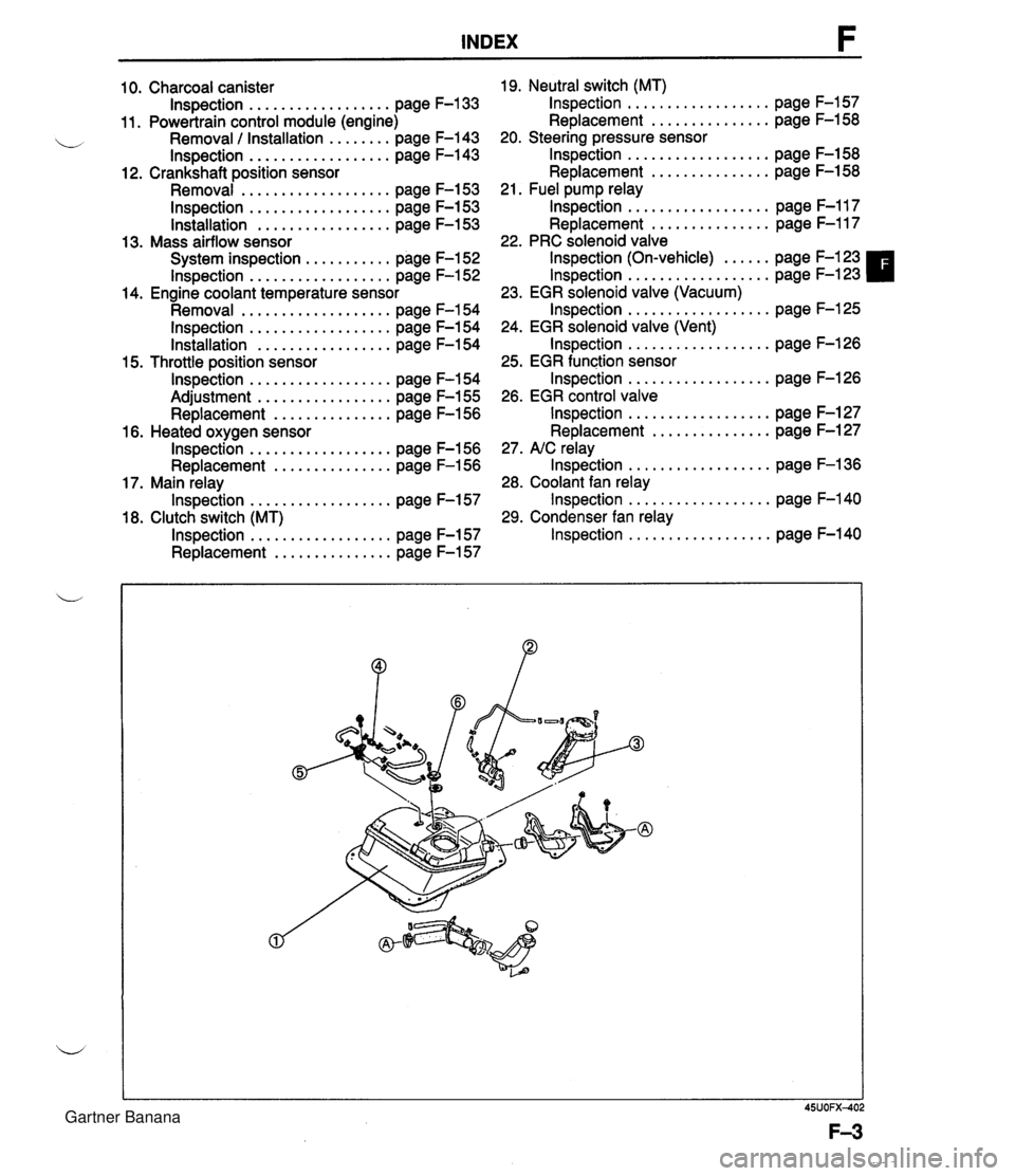
INDEX 10. Charcoal canister lnspection . . . . . . . . . . . . . . . . . . page F-133 11. Powertrain control module (engine) Removal / Installation . . . . . . . . page F-143 lnspection . . . . . . . . . . . . . . . . . . page F-143 12. Crankshaft position sensor Removal . . . . . . . . . . . . . . . . . . . page F-153 lnspection . . . . . . . . . . . . . . . . . . page F-153 lnstallation . . . . . . . . . . . . . . . . . page F-153 13. Mass airflow sensor System inspection . . . . . . . . . . . page F-152 lnspection . . . . . . . . . . . . . . . . . . page F-152 14. Engine coolant temperature sensor Removal . . . . . . . . . . . . . . . . . . . page F-154 lnspection . . . . . . . . . . . . . . . . . . page F-154 Installation . . . . . . . . . . . . . . . . . page F-154 15. Throttle position sensor lnspection . . . . . . . . . . . . . . . . . . page F-154 Adjustment . . . . . . . . . . . . . . . . . page F-155 Replacement . . . . . . . . . . . . . . . page F-156 16. Heated oxygen sensor lnspection . . . . . . . . . . . . . . . . . . page F-156 Replacement . . . . . . . . . . . . . . . page F-156 17. Main relay lnspection . . . . . . . . . . . . . . . . . . page F-157 18. Clutch switch (MT) lnspection . . . . . . . . . . . . . . . . . . page F-157 Replacement . . . . . . . . . . . . . . . page F-157 19. Neutral switch (MT) lnspection . . . . . . . . . . . . . . . . . . page F-157 Replacement . . . . . . . . . . . . . . . page F-158 20. Steering pressure sensor lnspection . . . . . . . . . . . . . . . . . . page F-158 Replacement . . . . . . . . . . . . . . . page F-158 21. Fuel pump relay lnspection . . . . . . . . . . . . . . . . . . page F-117 Replacement . . . . . . . . . . . . . . . page F-117 22. PRC solenoid valve lnspection (On-vehicle) . . . . . . page F-123 lnspection . . . . . . . . . . . . . . . . . . page F-123 23. EGR solenoid valve (Vacuum) lnspection . . . . . . . . . . . . . . . . . . page F-125 24. EGR solenoid valve (Vent) lnspection . . . . . . . . . . . . . . . . . . page F-126 25. EGR function sensor lnspection . . . . . . . . . . . . . . . . . . page F-126 26. EGR control valve lnspection . . . . . . . . . . . . . . . . . . page F-127 Replacement . . . . . . . . . . . . . . . page F-127 27. NC relay lnspection . . . . . . . . . . . . . . . . . . page F-136 28. Coolant fan relay lnspection . . . . . . . . . . . . . . . . . . page F-140 29. Condenser fan relay lnspection . . . . . . . . . . . . . . . . . . page F-140 Gartner Banana
Page 153 of 1708

INDEX 1. Fuel tank 4. Two-way check valve .................. Removal / Inspection / Inspection page F-132 Installation ................ page F-111 5. Three-way check valve .................. 2. Fuel filter Inspection page F-132 Replacement ............... page F-113 6. Fuel vapor valve .................. 3. Fuel pump Inspection page F-133 .................. Inspection page F-114 ............... Replacement page F-115 1. Three-way catalyst 2. Exhaust components d Inspection / Replacement .... page F-134 Removal / Inspection / Installation ............... page F-128 Gartner Banana
Page 154 of 1708
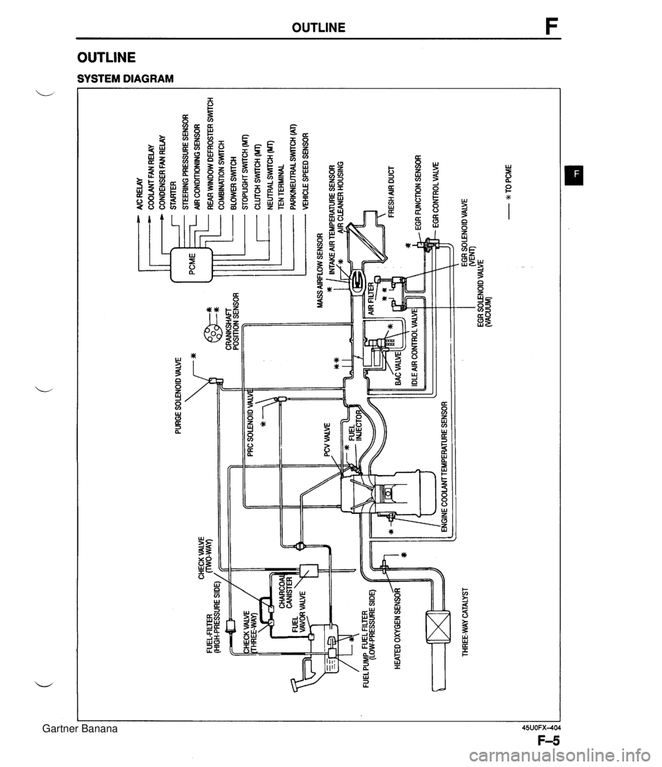
PURGE SOLENOID VALVE 7* AlC RELAY COOLANT FAN RELAY CONDENSER FAN RELAY STARTER STEERING PRESSURE SENSOR AIR CONDITIONING SENSOR ... CHECK VALVE FUEL-FILTER (HIGH-PRESSURE SIDE) / CRANKSHAFT POSITION SENSOR HEATED OXYGEN SENSOR ltT=I THREE-WAY CATALYST - REAR WINDOW DEFROSTER SWITCH COMBINATION SrmCH BLOWER SWlTCH STOPLIGHT SWITCH (MT) CLUTCH SWITCH (MT) - NEUTRALSWrrCH (MT) TEN TERMINAL PARWEUTRAL SWITCH (AT) VEHICLE SPEED SENSOR ENGINE COOLAMTEMPERATURE SENSOR EGR SOLENOID VALVE WEM) EGR SOLENOID VALVE (VACUUM) - w TO PCME Gartner Banana
Page 155 of 1708

OUTLINE VACUUM HOSE ROUTING DIAGRAM Gartner Banana
Page 156 of 1708

OUTLINE WIRING DIAGRAM Gartner Banana
Page 157 of 1708
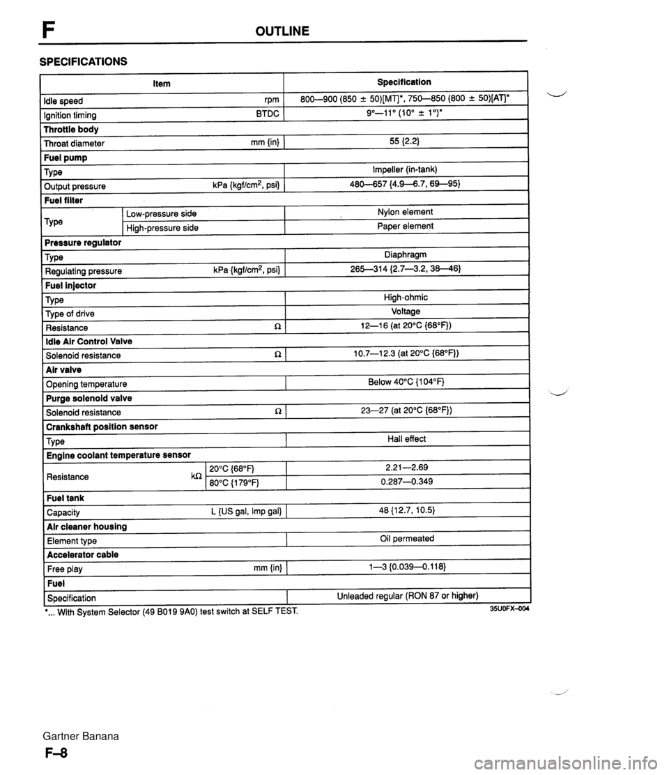
F OUTLINE SPECIFICATIONS Item Specification I Throttle body Throat diameter mm {in) I 55 I2.2) Idle speed rpm Ignition timing BTDC 800-900 (850 -+ 50)[MIb, 750-850 (800 + 50)[ATJe 9"-11" (10" k 1 ")* ~ut~~~ressure kPa {kgf/cm2, psi) 1 46-57 14.9--6.7,6%95) Fuel filter Fuel pump TY pe -- m&e regulator Impeller (in-tank) Low-pressure side Hi~h-pressure side Nylon element Paper element Fuel injector TY pe I High-ohmic Type Regulating pressure kPa {kgf/cm2, psi) Diaphragm 26S314 (2.7--3.2,38--46) ldle Air Control Valve Solenoid resistance n 1 10.7-1 2.3 (at 20°C {M°F)) Type of drive Resistance R Voltage 12-1 6 (at 20°C {68"F)) I Solenoid resistance 1 23-27 (at 20°C (68"FJ) I -- brankshaft position sensor d Air valve Opening temperature I Resistance Below 40°C {I 04°F) TY pe Capacity L {US gal, Imp gal) I 48 {12.7, 10.5) Air cleaner housing Purae solenoid valve Hall effect Engine coolant temperature sensor Free play mm (in) I 1-3 {0.0394.118) Fuel Specification 1 Unleaded regular (RON 87 or higher) Element type I I -. I *... With System Selector (49 B019 9AO) test switch at SELF TEST. 35UOFX-004 Oil permeated Accelerator cable Gartner Banana
Page 158 of 1708
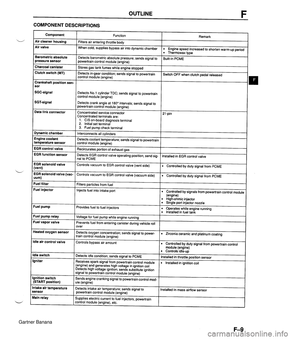
OUTLINE F COMPONENT DESCRIPTIONS Component Air cleaner housing Air valve Remark Function Filters air entering throttle body When cold, supplies bypass air into dynamicchamber w Engine speed increased to shorten warm-up period Thermowax type Barometric absolute pressure sensor Detects barometric absolute pressure; sends signal to powertrain control module (engine) 3uilt-in PCME Charcoal canister Clutch switch (MT) Stores gas tank fumes while engine stopped Detects in-gear condition: sends signal to powertrain control module (engine) --- ~witch OFF when clutch pedal released Crankshaft position sen- sor Detects No.1 cylinder TDC; sends signal to powertrain control module (engine) Detects crank angle at 180" intervals; sends signal to powertrain control module (engine) Data link connector Concentrated service connector Concentrated terminals are: 1. CIS on-board diagnosis terminal 2. Initial set terminal 3. Fuel pump check terminal Dynamic chamber Interconnects all cylinders Detects coolant temperature; sends signal to powertrain control module (engine) Recircurates oortion of exhaust aas Engine coolant temperature sensor EGR control valve lnstalled in EGR control valve EGR function sensor Detects EGR control valve operating position; send sig- nal to PCME EGR solenoid valve (vent) Controls vacuum to EGR control valve (vent side) Controlled by duty signal from PCME . - EGR solenoid valve (vac- Controls vacuum to EGR control valve (vacuum side) 0 Controlled by duty signal from PCME uum) Fuel filter Filters particles from fuel Injects fuel into intake port Fuel injector Controlled by signals from powertrain control module (engine) High-ohmic injector 0 Sinale port injector nozzle Fuel pump Provides fuel to fuel injectors 0 operates while engine running lnstalled in fuel tank Fuel pump relay Voltage for fuel pump while engine running Fuel vapor valve Prevents fuel from entering canister during vehicle roll over Heated oxygen sensor Detects oxygen concentration; sends signal to power- train control module (engine) 0 Zirconia ceramic and platinum coating ldle air control valve Controls bypass air amount Controlled by duty signal from powertrain control module (engine) Controls idle-up lnstalled in throttle position sensor lnstalled in ignition coil ldle switch Igniter Detects idle condition; sends signal to PCME Receives spark signal from powertrain control module (engine) and generates high voltage in ignition coil Detects high voltage ignition; sends substitute ignition signal to powertrain control module (engine) Ignition switch (START position) Sends engine cranking signal to powertrain control mod- ule (engine) Intake air temperature sensor Detects intake air temperature: sends signal to powertrain control module (engine) Installed in mass airflow sensor Main relay Supplies electric current to fuel injectors, powertrain control module (engine), etc. Gartner Banana
Page 159 of 1708
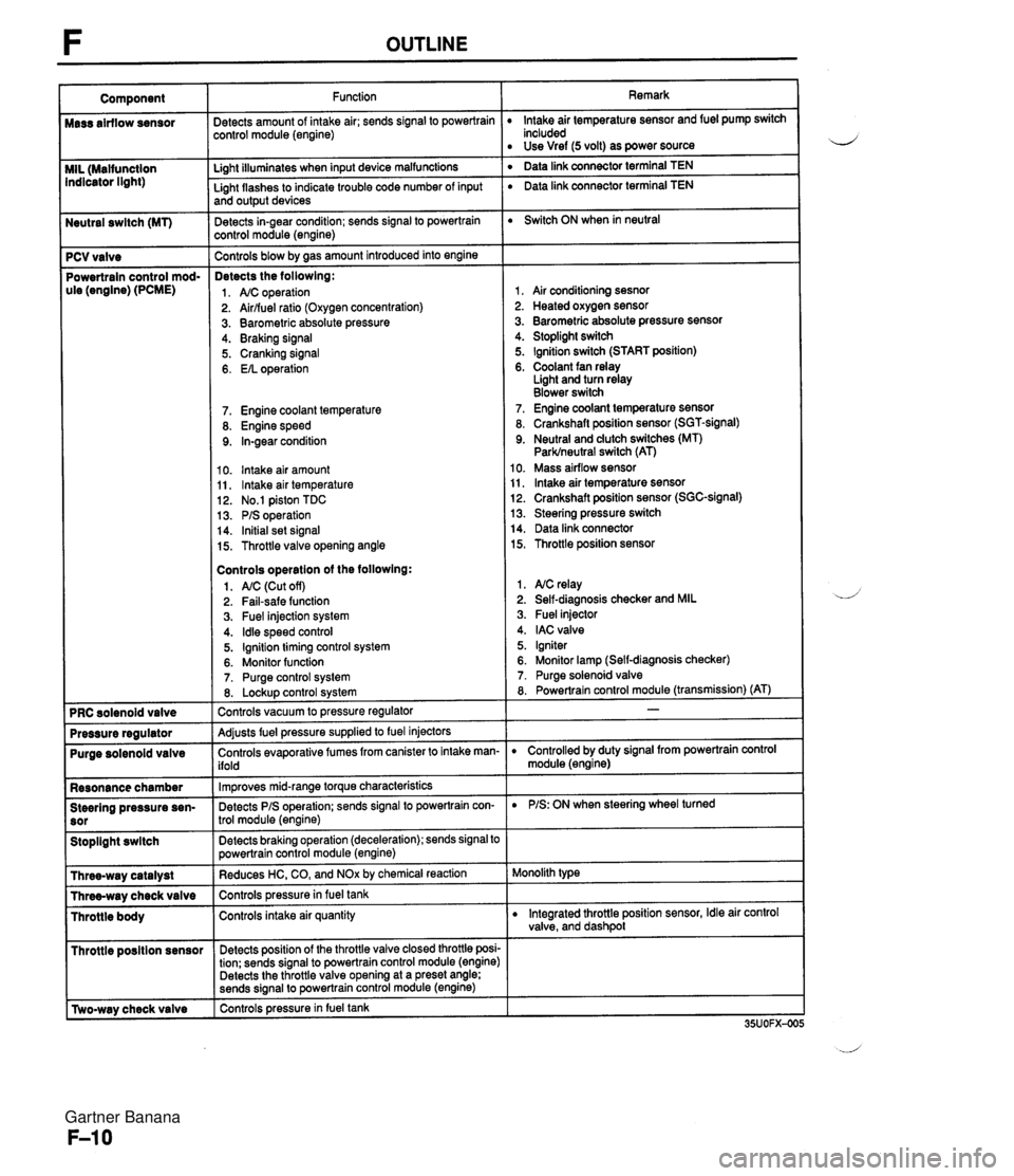
Neutral swltch (MT) 7 PCV valve Powertrain control mod- ule (engine) (PCME) Purge solenoid valve Resonance chamber Steering pressure sen- Stoplight swltch I Throttle posltion sensor r [Two-way check valve Function jetects amount of intake air; sends signal to powertrain :ontrol module (engine) Li~ht illuminates when input device malfunctions - Light flashes to indicate trouble code number of input and output devices Detects in-gear condition; sends signal to powertrain :ontrol module (engine) - Controls blow by aas amount introduced into engine Detects the followlng: 1. A/C operation 2. Airlfuel ratio (Oxygen concentration) 3. Barometric absolute pressure 4. Braking signal 5. Cranking signal 6. EIL operation 7. Engine coolant temperature 8. Engine speed 9. In-gear condition 10. lntake air amount 11, lntake air temperature 12. No.1 piston TDC 13. PIS operation 14. Initial set signal 15. Throttle valve opening angle Controls operatlon of the followlng: 1. AIC (Cut off) 2. Fail-safe function 3. Fuel injection system 4. ldle speed control 5. Ignition timing control system 6. Monitor function 7. Purge control system 8. Lockup control svstem Controls vacuum to pressure regulator -- Adjusts fuel pressure supplied to fuel injectors Controls evaporative fumes from canister to intake man- ifold -- lm~roves mid-ranae torque characteristics -. Detects PIS operation; sends signal to powertrain con- trol module (engine) -- Detects braking operation (deceleration); sends signal to powertrain control module (engine) Reduces HC, CO, and NOx by chemical reaction Controls pressurein fuel tank Controls intake air quantity Detects position of the throttle valve closed throttle posi- tion; sends signal to powertrain control module (engine) Detects the throttle valve opening at a preset angle; sends si~nal to powertrain control module (engine) controls pressure in fuel tank Remark lntake air temperature sensor and fuel pump switch included Use Vref (5 volt) as power source ' Data link connector terminal TEN ' Data link connector terminal TEN Switch ON when in neutral 1, Air conditioning sesnor 2. Heated oxygen sensor 3. Barometric absolute pressure sensor 4. Stoplight switch 5. Ignition switch (START position) 6. Coolant fan relay Light and turn relay Blower switch 7. Engine coolant temperature sensor 8. Crankshaft position sensor (SGT-signal) 9. Neutral and dutch switches (MT) Parklneutral switch (AT) 10. Mass airflow sensor 11, lntake air temperature sensor 12. Crankshaft position sensor (SGC-signal) 13. Steering pressure switch 14. Data link connector 15. Throttle position sensor 1. NC relay 2. Self-diagnosis checker and MIL 3. Fuel injector 4. IAC valve 5. Igniter 6. Monitor lamp (Self-diagnosis checker) 7. Purge solenoid valve 8. Powertrain control module (transmission) (AT) D Controlled by duty signal from powertrain control module (engine) D PIS: ON when steering wheel turned Monolith type D Integrated throttle position sensor, Idle air control valve, and dashpol Gartner Banana
Page 160 of 1708

TROUBLESHOOTING GUIDE F TROUBLESHOOTING GUIDE ENGINE CONTROL OPERATION CHART Output Devices and Engine Conditions ENGINE CONDITION CRANK- WARMING MEDIUM LOAD ING UP (DUR- ACCEL- HEAVY (COLD ERATION LOAD OUTPUT ENGINE) INGIDLE) COLD WARM DEVICE u I I I FUEL INJEC- FUELIN- nON Rich Normal JECToR AMOUNT Rich FUEL PUMP RELAY I IG: ON DECEL (ENGINE ERATION NOT RUNNING] No Injec- Fuel cut I Normal I tion IGNITER Depends on engine condition I PURGE SOLENOID VALVE OFF ON (Purge) OFF I I IDLE AIR ON ON ON CONTROL (Fixed (Closed ON (Fixed duty) (Closed OFF BAC VALVE duty) loop duty) loop duty) VALVE AIR VALVE OPEN CLOSED - AIC RELAY I OFF PRC SOLENOID VALVE OFF (Vacuum to pressure regulator) I I EGR SO- VENT ON LENOID OFF (System operates: amount of OFF JALVE VACUUM EGR changes) Gartner Banana