Diff MAZDA MX-5 1994 User Guide
[x] Cancel search | Manufacturer: MAZDA, Model Year: 1994, Model line: MX-5, Model: MAZDA MX-5 1994Pages: 1708, PDF Size: 82.34 MB
Page 86 of 1708

INSPECTION I REPAIR B WITH CARBON EX CUTTER 7. If the clearance exceeds specification, replace the valve and/or valve guide. 8. Measure height A of each valve guide. Replace the valve guide if necessary. Height: 18.3-18.9mm (0.7214.744 in) Replacement of valve guide Although the intake and exhaust valve guides are differ- ent, use the exhaust valve guide to replace the intake valve guide. Removal Remove the valve guide from the side opposite the com- bustion chamber with the SST. Installation 1. Assemble the SST so that depth L is as specified. Depth L: 18.3-18.9mm (0.7214.744 in) 2. Tighten the nut. 3. Tap the valve guide in from the side opposite the com- bustion chamber until the SST contacts the cylinder head. 4. Verify that the valve guide height is within specification. Height: 18.3-18.9mm (0.721-4.744 in) 5. If not, repeat steps 14. Gartner Banana
Page 91 of 1708

INSPECTION / REPAIR 4. Measure the cylinder bores in X and Y directions at three levels (A, B, and C) in each cylinder as shown. Cylinder bore mm(in) I Bore size Diameter 1 1 0.50 (0.020) oversize 1 83.50683.513 (3.2877-3.2879) 1 Standard 0.25 {0.010} oversize 5. Base the boring diameter on the diameter of an oversize piston. All cylinders must be the same diameter. (1) If the cylinder bore exceeds the maximum, rebore the cylinder to oversize. (2) If the difference between measurements A and C ex- ceeds the maximum taper, rebore the cylinder to oversize. 83.000--83.019 (3.2678-3.26841 83.25683.263 (3.2778-3.2780) Taper: 0.019mm (0.0007 in) max. (3) If the difference between measurements X and Y ex- ceeds the maximum out-of-round, rebore the cylin- der to oversize. Out-of-round: 0.019mm (0.0007 in) max. 6. If the upper part of a cylinder wall shows uneven wear, remove the ridge with a ridge reamer. OIL JET 1. Push the check ball and verify that it moves smoothly. 2. Blow through the oil jet and verify that air flows. Gartner Banana
Page 106 of 1708

ASSEMBLY CYLINDER HEAD Torque Specifications Valve Seal Note The intake and exhaust valve seals are different as shown. The exhaust valve seal has ridges on the top for iden- tification. Gartner Banana
Page 116 of 1708
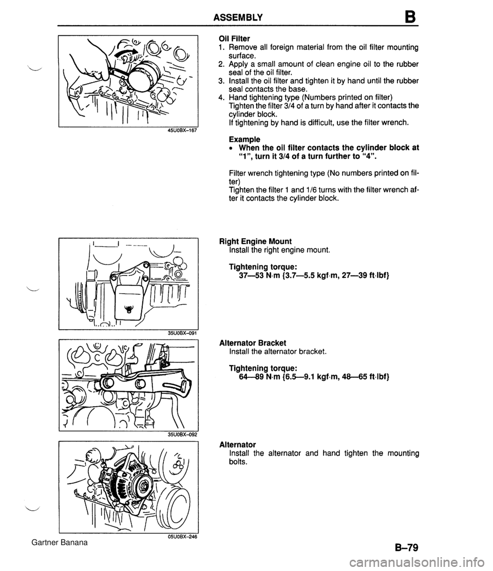
ASSEMBLY B Oil Filter 1. Remove all foreign material from the oil filter mounting surface. 2. Apply a small amount of clean engine oil to the rubber seal of the oil filter. 3. Install the oil filter and tighten it by hand until the rubber seal contacts the base. 4. Hand tightening type (Numbers printed on filter) Tighten the filter 314 of a turn by hand after it contacts the cylinder block. If tightening by hand is difficult, use the filter wrench. Example When the oil filter contacts the cylinder block at "l", turn it 314 of a turn further to "4". Filter wrench tightening type (No numbers printed on fil- ter) Tighten the filter 1 and 116 turns with the filter wrench af- ter it contacts the cylinder block. Right Engine Mount Install the right engine mount. Tightening torque: 37-53 N-m (3.7-5.5 kgf.m, 27-39 ft.lbf) Alternator Bracket Install the alternator bracket. Tightening torque: 64-49 N-m (6.5--9.1 kgf-m, 48-45 ft4bf) Alternator Install the alternator and hand tighten the mounting bolts. Gartner Banana
Page 126 of 1708
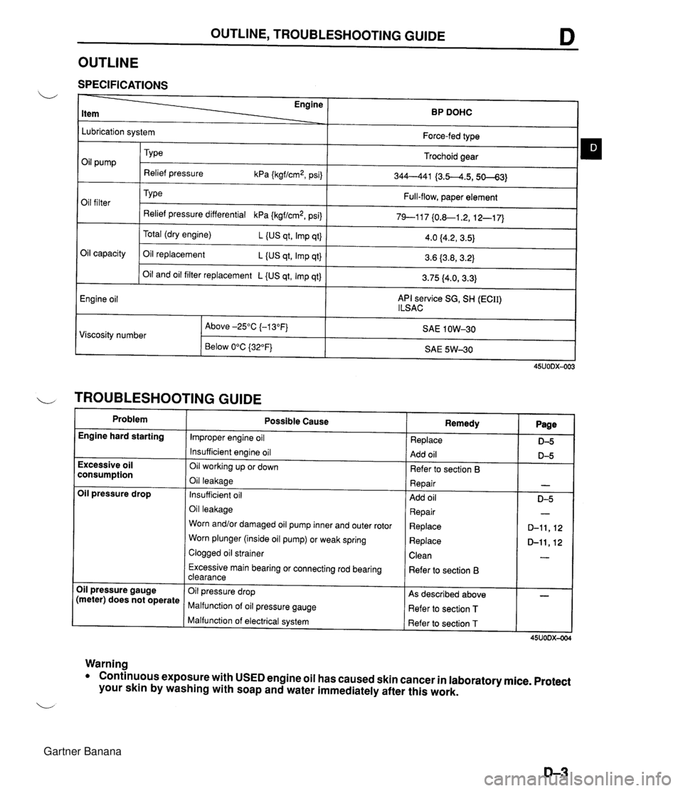
OUTLINE, TROUBLESHOOTING GUIDE D OUTLINE SPECIFICATIONS Engine BP DOHC Lubrication system Oil capacity Engine oil Force-fed type Trochoid gear 344--441 {3.5-4.5,50--63) Full-flow, paper element 79--117 {0.&1.2, 12-1 7) Oil pump Oil filter Oil and oil filter replacement L {US qt, Imp qt) API service SG, SH (ECII) l LSAC TY pe Relief pressure kPa {kgf/cm2, psi) Type Relief pressure differential kPa {kgf/cm2, psi) Total (dry engine) L (US qt, Imp qt} Oil replacement L {US qt, Imp qt} 3.75 (4.0, 3.3) 4.0 f4.2, 3.5) 3.6 (3.8,3.2) I TROUBLESHOOTING GUIDE Problem SAE 1 OW-30 SAE 5W-30 Viscosity number Engine hard starting 45UODX-003 Above -25°C (-1 3°F) Below 0°C {32"F} Excessive oil consumption Oil pressure drop Oil pressure gauge (meter) does not operate Warning Possible Cause Improper engine oil Insufficient engine oil Oil working up or down Oil leakage Insufficient oil Oil leakage Worn and/or damaged oil pump inner and outer rotor Worn plunger (inside oil pump) or weak spring Clogged oil strainer Excessive main bearing or connecting rod bearing clearance Oil pressure drop Malfunction of oil pressure gauge Malfunction of electrical system Remedy Replace Add oil Refer to section 6 Repair Add oil Repair Replace Replace Clean Refer to section B As described above Refer to section T Refer to section T Page D-5 D-5 - 0-5 - D-11,12 D-ll,12 - - 45UODX-004 Conthuous exposure with USED engine oil has caused skin cancer in laboratory mice. Protect your skin by washing with soap and water immediately after this work. Gartner Banana
Page 162 of 1708

TROUBLESHOOTING GUIDE USING THIS SECTION Introduction Most of the fuel and emission control system is electrically controlled, often making it difficult to diagnose '.-/ problems in the system, especially intermittent problems. Before undertaking actual checks, take a few minutes to talk with a customer who approaches with a driveability complaint. The customer is often a good source of information on such problems, especially intermittent ones. Through talks with the cus- tomer, one can find out what the symptoms are and under what conditions they occur. Work flow CHECK IN LISTEN TO CUSTOMER COMPLAINTS REFER TO TROUBLESHOOTING PAGE THAT - - - - - - - - - - - - - - - - - - Diagnostic index CORRESPONDS TO ACTUAL SYMPTOM (Refer to page F-18) 1-CHECKFORWHATISBADINSYSTEM--------------------- Inspection CHECKFORWHATPARTISBAD----------------------- Action Diagnostic index No.: / Each troubleshooting item is as- signed a number. TROUBLESHOOTING ITEM: There are 34 troubleshooting items. Choose the item that most closely corresponds to the actual symp- ,, tom. yes 1 CHECK OUT ---- -- TROUBLESHOOTING GUIDE F DESCRIPTION: Describes each troubleshooting item. ' PAGE: Shows the reference page. Gartner Banana
Page 364 of 1708

J TRANSMISSION REMOVAL 1. Obtain the code number and deactivate the audio antitheft system before disconnecting the battery. (Refer to section T.) 2. is connect the negative battery cable. 3. On level grand, jack up the vehicle and support it evenly on safety stands. 4. Drain the transmission oil into a suitable container. 5. Remove in the order shown in the figure, referring to Removal Note. I. Shift lever knob ?. Rear console 9. Clutch release cylinder 10. Starter I 1 3. Shift lever 11. speedometer cable 4. Undercover 12. Power plant frame (PPF) 5. Performance rod Removal Note ............... page J-1 1 6. Differential mounting pipe 13. Transmission 7. Exhaust pipe J Removal Note ............... page J-12 8. Propeller shaft Service ...................... section L Gartner Banana
Page 365 of 1708

TRANSMISSION J Removal note Power plant frame (PPF) 1. Disconnect the wire harness from the PPF. 2. Support the transmission with a jack. 3. Remove the PPF bracket. DIFFERENTIAT MOUNTING SPACER BOLT BOLT (MI 4 x 1.5) d1 SLEEVE BLOCK 35UOJX-031 4. Remove the differential-side bolts, and pry out the spacer. 5. Remove the differential mounting spacer. 6. Screw a long bolt (MI 4 x 1.5) into the sleeve. 7. Twist and pull the bolt and sleeve downward. 8. Install a bolt (M6 x 1) into the hole in the block to keep the sleeve from turning, and unscrew the long bolt (MI4 x 1.5). 9. Remove the bolt (M6x 1). Gartner Banana
Page 399 of 1708

TRANSMISSION J INSTALLATION 1. On level ground, jack up the vehicle and support it evenly on safety stands. 2. Install in the order shown in the figure, referring to lnstallation Note. L 3. Add the specified amount of the specified transmission oil. (Refer to page J-8.) 4. Warm up the engine and transmission, and inspect for oil leakage and transmission problems. 1. Transmission 7. Exhaust pipe Installation Note ............. page J-46 8. Performance rod 2. Power plant frame (PPF) 9. Differential mounting pipe Installation Note ............. page J-46 10. Undercover 3. S~eedometer cable 11. Shift lever w 4. ~iarter Installation Note ............. page J-47 5. Clutch release cylinder 12. Rear console 6. Propeller shaft 13. Shift lever knob Service ...................... section L Gartner Banana
Page 400 of 1708

J TRANSMISSION -=DIFFERENTIAL MOUNTING SPACER 45UOJX-054 Installation note Transmission 1. Tilt the engine by pushing up on the front of the oil pan with a wooden block and a transmission jack. d 2. Support the transmission with a transmission jack. 3. Raise the transmission into place and install and tighten the installation bolts. Tightening torque: 64-89 N-m (6.5--9.1 kgf-m, 48-65 ft.lbf) Power plant frame (PPF) 1. Install the differential mounting spacer. Tightening torque: 38-51 N.m (3.8-5.3 kgf-m, 28-38 ft-lbf) 2. Support the transmission with a jack so that it is level. 3. Position the PPF and tighten the transmission-side bolts by hand. 4. Verify that the sleeve is installed into the block. 5. Install the spacer and reamer bolts in the forward hole, then hand tighten them. 6. Snugly install the power plant frame bracket. 7. Tighten the transmission-side bolts. Tightening torque: 104-123 N-m (10.S12.6 kgf.m, 76.7-91.1 ft.lbf) 8. Tighten the differential-side bolts. Tightening torque: 104-1 23 N-m (1 0.S12.6 kgf.m, 76.7-91.1 ft-lbf) Gartner Banana