Diff MAZDA MX-5 1994 Owner's Manual
[x] Cancel search | Manufacturer: MAZDA, Model Year: 1994, Model line: MX-5, Model: MAZDA MX-5 1994Pages: 1708, PDF Size: 82.34 MB
Page 410 of 1708
TROUBLESHOOTING If the 3 steps on page K-8 are followed, the cause of the problem should be located. Another guide to faster location of the causes of problems, the QUICK DIAGNOSIS CHART, is on page K-1 0. b In this chart, numbers are used to indicate the components that may be the cause of 22 possible prob- lems. It is necessary to check only those components indicated by numbers during each step of the trouble- shooting process to locate the cause of the problem quickly. QUICK DIAGNOSIS CHART The QUICK DIAGNOSIS CHART shows different .problems and the relationship of components that might be the cause. 1. Components indicated in the "Adjustment" row indicate the possibility that the problem may result from an incorrect adjustment. Check the adjustment of each component, and readjust if necessary. 2. Components indicated in the "Self-DiagnosisWrow are diagnosed by the Powertrain control module (Transmission) self-diagnostic function. 3. Input and output signals of the Powertrain control module (Transmission) for components indicated in the "Tester" row can be easily checked with the Engine signal Monitor. 4. Components indicated in the "Mechanical System Test" row can be checked for malfunction by the re- sults of oil pressure test. 5. Components indicated in the "Road Test" row can be checked for malfunction by the results of the road test. 6. The numbers in the chart indicate the order of inspection for detecting malfunctions. 7. Circled numbers indicate that the transmission must be removed from the vehicle. 8. The checking, adjusting, repair, and replacement procedures for components are described in the page(s) shown in the "Reference page" row. Gartner Banana
Page 430 of 1708

ROAD TEST K ROAD TEST A road test is necessary to inspect for problems in the different gear ranges. If a range or function tar- b geted by the road test is found to have any problem, refer to the ELECTRONIC SYSTEM COMPONENT segment or the TRANSMISSION, OIL COOLER, DRIVE PLATE, and SHIFT MECHANISM segments of this section. Do the road test only when the ATF is 50-80°C (1 22-1 76°F). D-RANGE TEST Shift Point, Shift Pattern, and Shift Shock 1. Shift the selector lever to D range and select the Normal mode. 2. Accelerate the vehicle with half-and wide open throttle opening. 3. Verify that 1-2, 2-3, and 3-4 upshifts, downshifts, and lockup are obtained. The shift points must be as shown in the D range (Normal) shift diagram. Note There is fourth gear is any of the following conditions. A The cruise control is operating, and there is an 8kmIh (5 mph} difference between the preset cruise speed and the vehicle speed. B The SET or RESUME switch is ON. There is no lockup when water temperature is below 50°C (1 22°F) or in the throttle valve closed posi- tion. 4. Check the upshifts for shift shock or slippage in the same manner. 5. While driving in overdrive, shift the selector lever to S range and verify that 4-3 downshift immediately occurs, then decelerate and verify that engine braking effect is felt in only third gear and 2nd gears. D-range (Normal) shift diagram p'yJ ..,,*sw.. LOCKUP AVAILABLE WHEN ACCELERATING AND CRUSING LOCKUP AVAILABLE WHEN COASTING 0 20 (1 2) 40 (25) 60 (37) 80 {50) 100 (63) 1 20 (75) 140 (87) 1 60 (99) VEHICLE SPEED kmlh {mph) Gartner Banana
Page 432 of 1708

ROAD TEST K Evaluation I No lockup shift Condition No 1-2 up or downshift No 2-3 up or downshift No 3-4 up or downshift I Stuck lockup control solenoid valve Stuck locku~ control valve Possible Cause Stuck 1-2 shift solenoid valve Stuck 1-2 shift valve Stuck 2-3 shift solenoid valve Stuck 2-3 shift valve Stuck 3-4 shift solenoid valve Stuck 3-4 shift valve Incorrect shift point I No enaine brakina effect I Worn clutches, brakes I Misadjusted throttle position sensor Sticking shift valves Excessive shift shock or slippage Noise and Vibration Drive the vehicle in fourth gear (lockup), fourth gear (no lockup), and third gear (Hold) and listen closely for any out of the ordinary noise or vibration. The torque converter, propeller shaft, and differential can be sources of abnormal noise and vibration if they are not functioning properly. Check these when searching for sources of noise and vibration. Stuck accumulators Stuck or no one-way check orifice Stuck 3-2 control solenoid valve Stuck 3-2 control valve Worn clutches, brakes, or one-way clutch Kickdown Drive the vehicle in fourth gear, third gear, and 2nd gear and check that kickdown occurs for 4-+3,4-+2, 4+1,3+2,3+1, 2+1, and that the shift points are as shown in the shift diagram. ,U (Refer to pages K-29, 30.) S-RANGE TEST Shift Pattern For this test it is not necessary to inspect shift shock and shift points, since they are almost exactly the same as those for the D-range test. However, in the D-range (Normal) shift diagram, the shift points are different. In S range, the shift patterns for Normal mode are the same. 1. Shift the selector lever to S range and select the Normal mode. 2. Accelerate the vehicle and verify that 1-2 and 2-3 up-and downshifts are obtained, and that no fourth gear and no lockup (below approx. 100 kmlh (63 mph}) are obtained. 3. While driving in S range (Normal mode) and third gear, select the Hold mode and verify that third gear is held until ihe 3-2 downshift point as shown in the S range (Hold) shift diagram is achieved. 4. Accelerate the vehicle in S range (Hold mode) and verify that 2nd gear is held. S-range (Power) shift diagram LOCKUP AVAILABLE WHEN ACCELERATING AND CRUSING LOCKUP AVAILABLE WHEN COASTING -. - VEHICLE SPEED kmlh (rnph} Gartner Banana
Page 433 of 1708

ROAD TEST (Hold) shift diagram LOCKUP AVAILABLE WHEN COASTING 818 718 - 618 - 518 ' 418 - 3/8 ' 218 - 118 - 018 0 20 (1 2) 40 (25) 60 (37) 80 (50) 100 (63) 120 (75) 140 (87) 160 (99) VEHICLE SPEED kmh {mph} Noise and Vibration Drive the vehicle in 2nd (Hold) and listen closely for any out of the ordinary noise or vibration. The torque converter, propeller shift, and differential can be sources of abnormal noise and vibration if they are not functioning properly. Check these when searching for sources of noise and vibration. L-RANGE TEST Shift Pattern For this test it is not necessary to inspect shift shock and shift points, since they are almost exactly the same as those for the D-range test. However, in the D-range (Normal) shift diagram, the shift points are different. ,, In L-range, the shift patterns for Normal mode are the same. 1. Shift the selector lever to L-range and select the Normal mode. 2. Accelerate the vehicle and verify that 1-2 up and downshifts are obtained, and that no third gear, no fourth gear, and no lockup are obtained. 3. Drive in 1 st gear, then decelerate and verify that engine braking effect is felt. 4. While driving in D-range (Hold mode) and third gear, shift the selector lever to L-range and verify that third gear is held until the 3-2 downshift point as shown in the L-range (Hold) shift diagram, and that 2nd gear is held until 2-1 downshift point is achieved. 5. Accelerate the vehicle in L-range (Hold mode) and verify that 1 st gear is held. L-range (Power) shift diagram LOCKUP AVAILABLE WHEN COASTING o 20 (12) 40 (25) 60 (37) 80 (50) 100 163) i 20 (75) 14dp7) 160 pgj VEHICLE SPEED kwh {mph) Gartner Banana
Page 434 of 1708

ROAD TEST L-range (Hold) shift diagram LOCKUP AVAILABLE WHEN COASTING 0 20 (1 2) 40 (25) 60 {37) 80 {50) 100 {63) 120 {75) 1 40 (87) 1 60 (99) VEHICLE SPEED kmh {mph) Noise and Vibration Drive the vehicle in 1 st (Hold) and listen closely for any out of the ordinary noise or vibration. The torque converter, propeller shift, and differential can be sources of abnormal noise and vibration if they are not functioning properly. Check these when searching for sources of noise and vibration. P-RANGE TEST 1. Shift into P range on a gentle slope, release the brake, and verify that the vehicle does not roll. 2. Shift into P range while driving the vehicle at 4 kmlh (2.5 mph) maximum on a level surface, and verify that the vehicle stops. Gartner Banana
Page 543 of 1708
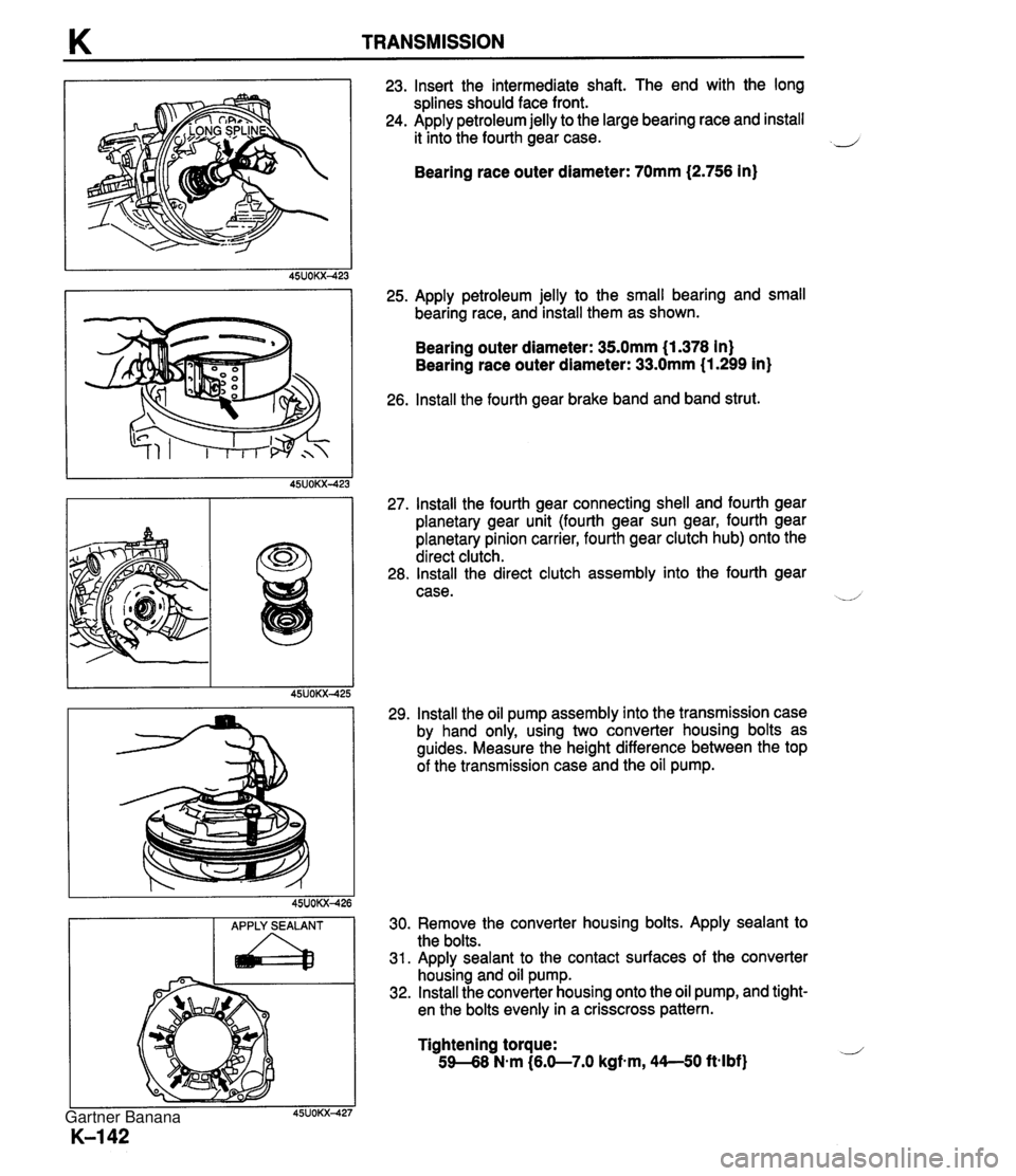
K TRANSMISSION APPLY SEALANT a 23. Insert the intermediate shaft. The end with the long splines should face front. 24. Apply petroleum jelly to the large bearing race and install it into the fourth gear case. 2 Bearing race outer diameter: 70mm (2.756 in) 25. Apply petroleum jelly to the small bearing and small bearing race, and install them as shown. Bearing outer diameter: 35.0mm (1.378 in) Bearing race outer diameter: 33.0mm (1.299 in) 26. lnstall the fourth gear brake band and band strut. 27. lnstall the fourth gear connecting shell and fourth gear planetary gear unit (fourth gear sun gear, fourth gear planetary pinion carrier, fourth gear clutch hub) onto the direct clutch. 28. lnstall the direct clutch assembly into the fourth gear case. --/ 29. lnstall the oil pump assembly into the transmission case by hand only, using two converter housing bolts as guides. Measure the height difference between the top of the transmission case and the oil pump. 30. Remove the converter housing bolts. Apply sealant to the bolts. 31. Apply sealant to the contact surfaces of the converter housing and oil pump. 32. lnstall the converter housing onto the oil pump, and tight- en the bolts evenly in a crisscross pattern. Tightening torque: 59-68 N-m (6.0-7.0 kgfm, 44--50 ft4bf) Gartner Banana
Page 551 of 1708

K TRANSMISSION 5. Tighten the transmission-side bolts. Tightening torque: 104--123 N.m (10.6-12.6 kgf-m, 76.7-91.1 ft-lbf} 6. Tighten the differential-side bolts. Tightening torque: lO4--123 N.m {10.6-1 2.6 kgf-m, 76.7-91.1 ft-lbf} 7. Remove the jack. 8. Measure distance A with a straightedge and vernier cali- pers. Distance A: 51.5-61 Smm (2.023--2.417 in} 9. If the distance is not within specification, reposition the power plant frame at the transmission. Gartner Banana
Page 586 of 1708
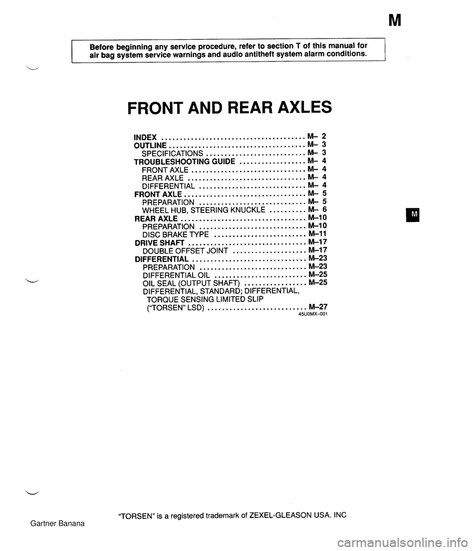
Before beginning any service procedure. refer to section T of this manual for air bag system service warnings and audio antitheft system alarm conditions . FRONT AND REAR AXLES ....................................... INDEX M- 2 ..................................... OUTLINE M- 3 SPECIFICATIONS ........................... M- 3 TROUBLESHOOTING GUIDE .................. M- 4 ............................... FRONT AXLE M- 4 ................................ REAR AXLE M- 4 ............................. DIFFERENTIAL M- 4 ................................. FRONT AXLE M- 5 PREPARATION ............................. M- 5 WHEEL HUB. STEERING KNUCKLE .......... M- 6 .................................. REAR AXLE M-10 PREPARATION ............................. M-10 ......................... DISC BRAKE TYPE M-11 ................................ DRIVE SHAFT M-17 .................... DOUBLE OFFSET JOINT M-17 ............................... DIFFERENTIAL M-23 PREPARATION ............................. M-23 DIFFERENTIAL OIL ......................... M-25 ................. OIL SEAL (OUTPUT SHAFT) M-25 DIFFERENTIAL. STANDARD; DIFFERENTIAL. TORQUE SENSING LIMITED SLIP ("TORSEN" LSD) ........................... M-27 45UOMX-001 "TORSEN" is a registered trademark of ZEXEL-GLEASON USA . INC Gartner Banana
Page 587 of 1708

INDEX INDEX OIL SPECIFICATION ABOVE -1 8°C (O°F1: GL-5. SAE 90 / I 1 ,BELOW -1 8°C Ioo~: GL-5, SAE 80 ..-.. - - - - .. - ...... SERVICE, SECTION L REAR'BRAKE PROPELLER SHACT SERVICE, SECTION P FRONT-BRAKE SERVICE SECTION P 1. Front axle Inspection / Removal / Installation ............... page M- 6 Disassembly 1 Inspection / Assembly. ............... page M- 8 2. Rear axle Inspection / Removal / Installation ............... page M-1 1 Disassembly 1 Inspection / Assembly ................ page M-13 M-2 3. Drive shaft Ins~ection / Removal 1 ............... Installation page M-17 Overhaul .................. page M-19 4. Differential (Standard, Torque sensing limited slip differential) Differential oil .............. page M-25 . Oil seal (Output shaft) ...... page M-25 Removal 1 Installation ....... page M-27 Overhaul .................. page M-32 Gartner Banana
Page 588 of 1708

OUTLINE OUTLINE Front axle Rear axle Differentlal Drive shaft Item I Specifications TY pe Bearing Double-wishbone Angular ball bearing Maximum wheel bearing play mm {in} TY pe Bearing 0.05 {0.002} Double-wishbone Angular ball bearing Maximum wheel bearing play mm {in} Type Reduction gear Reduction ratio Oil I Viscosity 0.05 {0.002} -- ---- Differential gear Ring gear size mm {in} Grade Above -1 8°C {O°F}: SAE 90 Below -1 8°C {O°F}: SAE 80 Standard Hypoid gear Straight-bevel gear 182.88 {7.20) API service GL-5 I Capacity L {US qt. imp qt} I 1 .OO {I .06,0.88) "TORSEN" LSD Worm gear 4.100 TY ~e Length mm {in} Constant velocity (double offset) joint 640.6 I25.220) 45UOMX-00 Gartner Banana