Diff MAZDA MX-5 1994 Repair Manual
[x] Cancel search | Manufacturer: MAZDA, Model Year: 1994, Model line: MX-5, Model: MAZDA MX-5 1994Pages: 1708, PDF Size: 82.34 MB
Page 626 of 1708
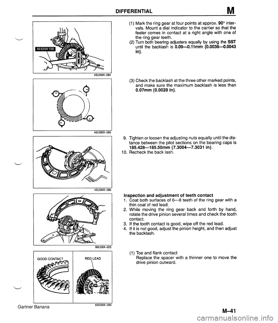
DIFFERENTIAL M (1) Mark the ring gear at four points at approx. 90" inter- vals. Mount a dial indicator to the carrier so that the feeler comes in contact at a right angle with one of the ring gear teeth. (2) Turn both bearing adjusters equally by using the SST until the backlash is 0.09-0.11mm {0.0036-€).0043 in). (3) Check the backlash at the three other marked points, and make sure the maximum backlash is less than 0.07mm (0.0028 in). 9. Tighten or loosen the adjusting nuts equally until the dis- tance between the pilot sections on the bearing caps is 185.428-1 85SOmm (7.3004--7.3031 in). 10. Recheck the back lash. Inspection and adjustment of teeth contact 1. Coat both surfaces of 6-8 teeth of the ring gear with a thin coat of red lead. 2. While moving the ring gear back and forth by hand, rotate the drive pinion several times and check the tooth contact. 3. If the tooth contact is good, wipe off the red lead. 4. If it is not good, adjust the pinion height, and then adjust the backlash. (1) Toe and flank contact Replace the spacer with a thinner one to move the drive pinion outward. Gartner Banana
Page 627 of 1708

M DIFFERENTIAL I HEEL CONTACT FACE CONTACT I (2) Heel and face contact Replace the spacer with a thicker one to bring the drive pinion in. d Bearing caps 1. Tighten the bearing cap bolts. Tightening torque: 37-52 N-m {3.8-5.3 kgf-m, 27-38 ft4bf) 2. Install the lock plates on the bearing caps. Tightening torque: 18-25 N.m (1.8-2.6 kgf-m, 13-19 ft.lbf) Differential case 1. Apply sealant to the housing face. 2. Tighten the bolts. Tightening torque: 23-26 N.m (2.3-2.7 kgf.m, 17-20 ft.lbf) Output shaft 1. Install a new clip. 2. Install the output shafts into the side gears by lightly tap- ping them with a plastic hammer. 3. Verify that the output shafts are hooked into the side gears by pulling them by hand. Gartner Banana
Page 639 of 1708

N MANUAL STEERING STEERING GEAR AND LINKAGE Removal / Installation 1. Turn the wheels to the straight-ahead position. 2. Loosen the wheel lug nuts. 4 3. On level ground, jack up the front of the vehicle and support it on safety stands. 4. Remove the wheel. Note Turning the steering wheel while the steering gear is removed will make reinstallation difficult. Do not turn the steering wheel while the steering gear is removed. If the steering wheel is turned in that condi- tion, the clockspring connector may have to be adjusted. (Refer to section T.) 5. Remove the undercover. 6. With the wheels in the straight-ahead position, remove in the order shown in the figure. 7. Install in the reverse order of removal. 8. Adjust the front wheel alignment. (Refer to section R.) 1. Cotter pin 4. Intermediate shaft bolt 5. Mounting bracket bolt .i 2. Nut 3. Tie-rod endlsteering knuckle 6. Steering gear and linkage Removal Note . . . . . . . . . . . . . . . . page N-7 Gartner Banana
Page 652 of 1708

ENGINE SPEED SENSING POWER STEERING N STEERING GEAR AND LINKAGE Removal / Installation 1. Turn the wheels to the straight-ahead position. 2. Loosen the wheel lug nuts. 3. On level ground, jack up the front of the vehicle and support it on safety stands. 4. Remove the wheels. Note Turning the steering wheel while the steering gear is removed will make reinstallation difficult. Do not turn the steering wheel while the steering gear is removed. If the steering wheel is turned in that condi- tion, the clockspring connector may have to be adjusted. (Refer to section T.) 5. Remove in the order shown in the figure, referring to Removal Note. 6. With the wheels in the straight-ahead position, install in the reverse order of removal. 7. Tighten all necessary bolts and nuts to the specified torque. 8. After installation: (1) Check for fluid leakage. (Refer to page N-22.) (2) Bleed air from the system. (Refer to page N-21.) (3) Adjust the front wheel alignment. (Refer to section R.) 1. Cotter pin 5. Pressure pipe 2. Nut ~emovai Note ............... page N-26 3. Tie-rod endlsteering knuckle 6. Return hose Removal Note ............... page N- 7 7. Mounting bracket bolt 4. Bolt 8. Steering gear and linkage Gartner Banana
Page 729 of 1708

Q OUTLINE, TROUBLESHOOTING GUIDE OUTLINE Wheels SPECIFICATIONS Tires -2 TROUBLESHOOTING GUIDE Temporary spare 14x4T - - TY Pe Item Size Offset mm {in) Pitch circle diameter mm {in) Material Size Air pressure kPa {kgf/cm2, psi} Standard 14x5 112-JJ 45 11.77) 1 00 (3.94) Aluminum Alloy 185160R14 82H 177 {I .8, 26) Page Excessive or irregu- tar tire wear Premature tire wear Tire squeal body vibration I Unbalanced wheel@) 1 Adjust I Q-5 Steel T1 l5/7ODl4 41 2 {4.2,60) Action Problem 1 Tre deterioration 1 Replace I - I Deformed wheel(s) or tire(s) I Repair or replace I - Possible Cause Refer to page Q-4 for details. Road noise or I Insufficient tire pressure [ Adjust Incorrect tire pressure ( Adjust Incorrect tire pressure 1 Adjust Q-3 Q-3 0-3 Shake [Steering wheel "Ibrates Excessive tire and wheel runout Loose lug nuts Unbalanced wheel(s) Insufficient tire pressure Unevenly worn tires Malfunction of shock absorber Loose shock absorber mounting bolts Stuck or damaged lower arm ball joint Cracked or worn suspension bushings Shimmy (Steering wheel vibrates lefiIright) Replace Tighten Adjust or replace Adjust Replace Replace Tighten Replace Replace Irregular tire wear Excessive tire and wheel runout Loose lug nuts Unbalanced wheel(s) - Q4 Q-5 Q-3 - section R section R section R section R Cracked or worn engine mount Cracked or worn steering gear mount Loose steering gear mounting bolts Stuck or damaged steering ball joint I Damaged or worn front wheel bearing ( Replace ( section M Replace Replace Tighten Adjust or replace I Improperly adjusted front wheel alignment 1 Adjust I section R Uneven (one-sided) I Unequal tire pressures 1 Adjust 1 Q-3 - - Q-4 Q-5 Replace Replace Tighten Replace section B section N section N section N braking Steering wheel I Incorrect tire pressure 1 Adjust doesn't return properly or pulls to either left or right . General driving Instability Excessive steering (2-3 wheel play Irregular tire wear (lefthight) Unequal tire pressures Different types or brands of tires mixed (leftlright) Loose lug nuts Unequal tire pressures Damaged or unbalanced wheel(s) Loose lug nuts Loose lug nuts I 15UOQX-00 Replace Adjust Replace Tighten Adjust Replace or adjust Tighten Tighten - Q-3 - Q-4 Q-3 Q-5 Q-4 Q-4 Gartner Banana
Page 736 of 1708

OUTLINE OUTLINE SPECIFICATIONS Front Suspension - Transmission item (Stabilizer Specifications MT I AT - I Susoension tvoe I . , . , I . , Shock absorber Cylindrical double acting, low-pressure-gas charged I Double-wishbone TY pe Torsion bar Coil spring I - Diameter mm linl I 20.0 10.79) Identification mark color 19.0 (0.75) White Wire diameter mm (in) Coil inner diameter mm {in) I Blue Free length mm {in) Coil number 11 .O (0.43) 83 i3.27) 11 .O (0.43) 83 (3.27) 292.5 (1 1 32) 6.32 3 +. 3 (0.12 + 0.12) 0°18' + 18' Total toe-in I - I 35UORX-001 Rear Suspension 302.0 (1 1.89) 6.32 mm {in) degree Total toe-in (per side) 1 degree Front wheel alignment (Unladedt1) 0°09' +. 09' Caster anglee3 4"26' +. 45' Kingpin angle 11 "20' Maximum steering angle Transmission Specifications MT I AT Item Differential - Suspension type Inner Outer "TORSEN" LSD 1 Standard Double-wishbone Coil springs 370 23' a 2" 32" 32' -t 2" Camber anglee2 Torsion bar 12.0 (0.47) 1 11.0 (0.43) 1 11 .O (0.43) Cylindrical double acting, low-pressure-gas charged - Stabilizer Identification mark color Wire diameter mm {in) 0°24' + 45' Type Diameter mm {in) I Coil number I 7.68 I 7.96 I Shock absorber Yellow 10.1 {0.40} Coil inner diameter mm {in) Free length mm {in) Green 10.2 {0.40) 35UORX-002 *I Fuel tank full; radiator coolant and engine oil at specified levels; spare tire, jack, and tools in designated positions. '2 Difference between left and right must not exceed I O. '3 Difference between left and right must not exceed 1'30'. "TORSEN" is a registered trademark of ZEXEL-GLEASON USA.INC 83 I3.27) 348.5 j13.72) Rear wheel alignment (Unladed*') 83 (3.27) 356.5 (1 4.04) Total toe-in Total toe-in (per side) mm (in) degree degree 3 -c 3 (0.12 + 0.121 0°18' + 18' 0°09' + 09' Camber angle*2 -0°43' 2 30' Gartner Banana
Page 738 of 1708
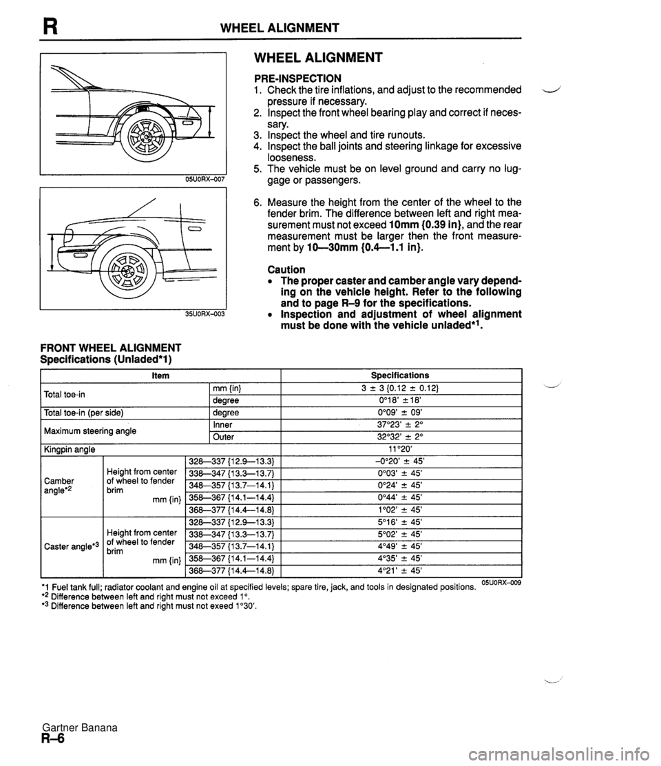
WHEEL ALIGNMENT WHEEL ALIGNMENT FRONT WHEEL ALIGNMENT Specifications (Unladed*l) PRE-INSPECTION 1. Check the tire inflations, and adjust to the recommended d pressure if necessary. 2. lnspect the front wheel bearing play and correct if neces- sary. 3. lnspect the wheel and tire runouts. 4. Inspect the ball joints and steering linkage for excessive looseness. 5. The vehicle must be on level ground and carry no lug- gage or passengers. 6. Measure the height from the center of the wheel to the fender brim. The difference between left and right mea- surement must not exceed 10mm (0.39 in), and the rear measurement must be larger then the front measure- ment by 10-30mm (0.4--1.1 in). Caution The proper caster and camber angle vary depend- ing on the vehicle height. Refer to the following and to page R-9 for the specifications. Inspection and adjustment of wheel alignment must be done with the vehicle unladed*'. . . I Y -- t~otal toe-in l~er side) I 1 dearee 0'09' + 09' I Total toe-in 3 2 3 I0.12 2 0.12) 0'1 8' 2 18' mm (in) dearee Maximum steering angle U - Inner Outer 11 '20' -0°20' 2 45' 0'03' ? 45' 0'24' 2 45' 0°44' -+ 45' 1'02' -+ 45' 5'1 6' ? 45' 5O02' -+ 45' 4O49' 2 45' 4'35' -+ 45' 4'21 ' -+ 45' I Kingpin angle 37"23' -+ 2" 32O32' 2 2" '1 Fuel tank full; radiator coolant and engine oil at specified levels; spare tire, jack, and tools in designated positions. OSUORX-009 ** Difference between left and right must not exceed lo. '3 Difference between left and right must not exeed 1'30'. 328-337 {I 2.9-1 3.3) 338-347 {I 3.3-1 3.7) 340-357 I13.7-14.1) 358-367 {I 4.1-14.4) 36&377 {I 4.4--14.8) 328-337 {I 2.9--13.3) 338-347 {I 3.3-1 3.7) 348-357 113.7-14.1) 358-367 {I 4.1-14.4) 368-377 {I 4.4--14.8) Camber angleg2 Caster angle*3 Height from center Of wheel to fender brim mm {in) Height from center Of wheel to fender brim mm (in) Gartner Banana
Page 741 of 1708

WHEEL ALIGNMENT REAR WHEEL ALIGNMENT Specifications (Unladed*) I Item I Specifications I L *' Fuel tank full; radiator coolant and engine oil at specified levels; spare tire, jack, and tools in designated positions. 05Uo~x-01~ *2 Difference between the leff and right must be exeed lo. 3 + 3 i0.12 * 0.12) 0'18' k18' 0'09' 2 09' -1 "08' +. 30' Total toe-in Total toe-in (per side) Camber angle'' LEFT WHEEL - mm {in) degree degree INCREASE I 1 346-355 (1 3.6-1 4.0) Height from center of wheel to fender brim'2 mm Iin) RIGHT WHEEL C INCREASE 356-3135 {14.0-14.4) 366-375 {I 4.4--14.8) 376-385 {I 4.8-1 5.2) 386--395 {I 5.2-1 5.6) LEFT WHEEL -C -0°54' r 30' -0'43' 2 30' -0°35' r 30' -0'30' +. 30' Toe-in Toe-in is adjusted by turning the front and/or rear adjust- ing cam bolts at the lower arm. Caution Adjust the toe-in before adjusting the camber. 1. Loosen the front and/or rear cam nuts. 2. Turn the front and/or rear adjusting cam bolts to provide the correct toe-in. I Counter- Counter- Decrease Clockwise Clockwise clockwise clockwise Toe-in Note Turning the front cam one graduation changes the toe-in about 2.8mm (0.11 in} and the camber about 15'. Turning the rear cam one graduation changes the toe-in about 2.8mm I0.11 in} and the camber about 6'. 3. 'Adjust the camber. Left wheel Camber Camber is adjusted by turning the front and rear cams at the lower arm. Right wheel Caution Adjust the camber after adjusting the toe-in. Front cam I Rear cam I Front cam I Rear cam 1. Loosen the front and rear cam nuts. 2. Turn the front and rear adjusting cam bolts the same amount in the opposite direction to provide the correct camber angle. Gartner Banana
Page 758 of 1708

R REAR SUSPENSION (DOUBLE-WISHBONE) CROSSMEMBER Removal I Inspection I Installation 1. Jack up the vehicle and support it with safety stands. 2. Remove the wheels and tires. d 3. Remove the differential and the power plant frame. (Refer to section M.) 4. Lower the crossmember and other suspension parts as an assembly, and then separate the parts. 5. Remove in the order shown in the figure. 6. lnspect parts and repair or replace as necessary. 7. Install in the reverse order of removal. 8. Loosely tighten the stabilizer bracket, upper arm, and lower arm bolts. Tighten all other nuts and bolts to the specified torques. 9. Lower the vehicle. 10. With the vehicle unloaded, tighten the stabilizer bracket, upper arm, and lower arm bolts to the specified torques. 11. Adjust the rear wheel alignment. (Refer to page R-9.) 12. Bleed the air from the brake system. (Refer to section P.) 13. Adjust the parking brake lever stroke. (Refer to section P.) 1. Differential mounting pipe 6. Shock absorber bolt 2. Parking brake cable 7. Stabilizer bracket Removal / Installation . . . . . . . . . Section P 8. Upper arm bolt 3. Brake pipe 9. Adjusting cam bolt Removal / Installation . . . . . . . . . Section P 10. Rear crossmember assembly 4. Brake pipe joint Inspect for damage 5. Battery cable bracket Gartner Banana
Page 1061 of 1708

T SRS AIR BAG SYSTEM GREEN LIGHT -+@ @ . ACTIVATION SWITCH RED ' LIGHT (3) Inspect the SST (Refer to page T-217.) (4) Connect the SST to the air bag module. 5. Connect the red clip of the SST to the positive battery ter- minal and the black clip to the negative terminal. 6. Verify that the red light on the SST is illuminated. 7. Make sure all persons are standing at least 6 m (20 ft} from the vehicle. 8. Press the activation switch on the SST to deploy the air bag. Air Bag Disposal Warning The air bag is very hot immediately after it de- ploys. You can be burned. Do not touch the air bag module for at least 15 minutes after deployment. Warning Pouring water on a deployed air bag is danger- ous. The water will mix with the residual gases to form a gas that can make breathing difficult if in- haled. Do not pour water on the deployed air bag module. Warning A deployed air bag module may contain deposits of sodium hydroxide, a caustic by-product of the gas-generated combustion. If this substance gets in your eyes or on your hands, it can cause irrita- tion and itching. When handling a deployed air bag module, wear gloves and safety glasses. 1. Put on gloves and safety glasses. 2. Place the deployed air bag module in a plastic bag, seal it, and then dispose of it. 3. Wash your hands after removing your gloves. Gartner Banana