ECU MAZDA MX-5 1994 User Guide
[x] Cancel search | Manufacturer: MAZDA, Model Year: 1994, Model line: MX-5, Model: MAZDA MX-5 1994Pages: 1708, PDF Size: 82.34 MB
Page 391 of 1708

TRANSMISSION J & BEARING HOUSING Locknut (Countershaft) 1. Shift the clutch hub sleeves into 1 st and Reverse gears to lock the rotation of the mainshaft. 2. Connect the SST to the mainshaft and secure it in a vise. 3. Install a new locknut and tighten it. Tightening torque: 128-1 96 N.m (13-20 kgf-m, 95--144 ft-lbf) 4. Use a chisel to stake the locknut. Gartner Banana
Page 397 of 1708
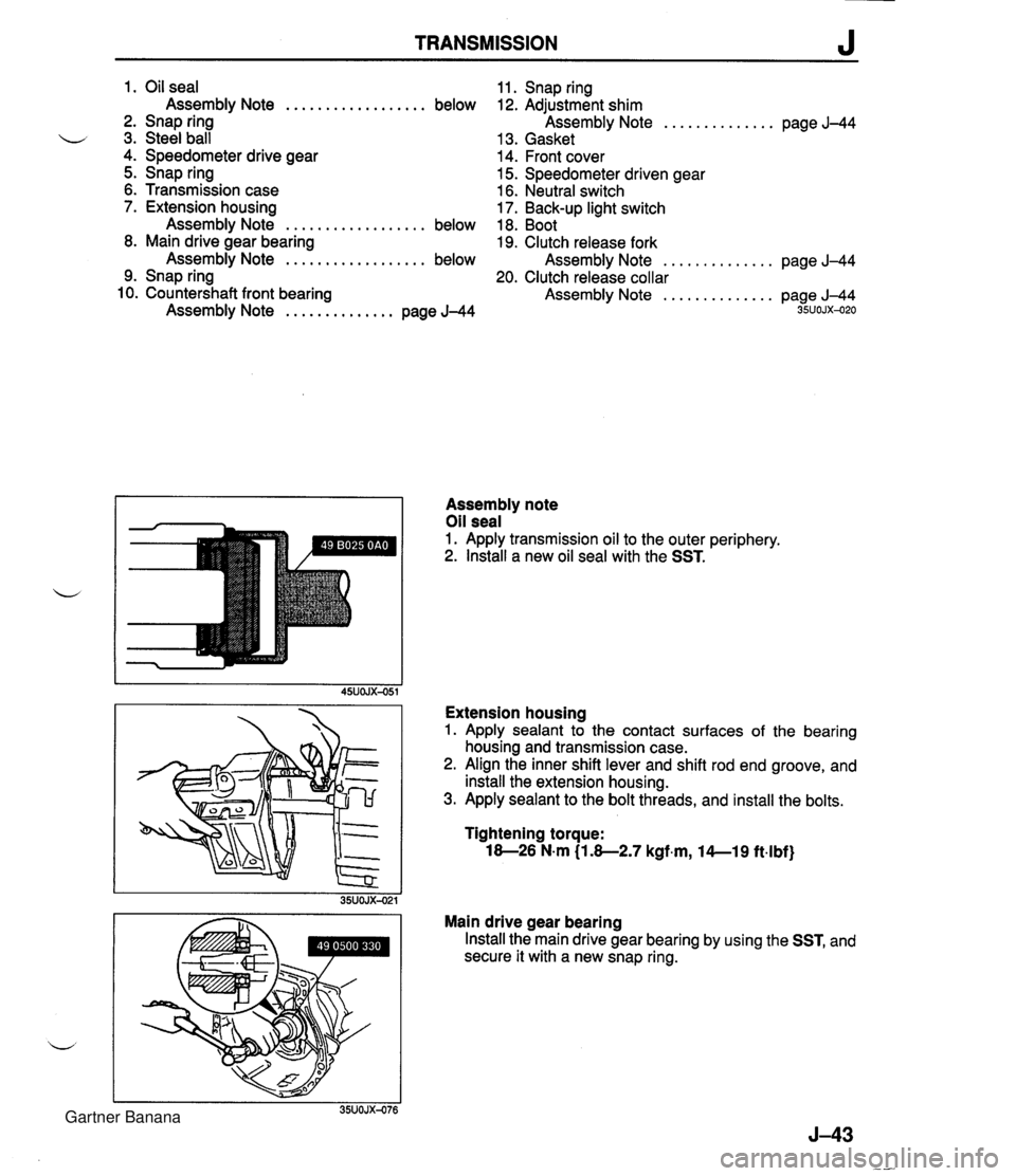
TRANSMISSION J 1. Oil seal Assembly Note .................. below 2. Snap ring u 3. Steel ball 4. Speedometer drive gear 5. Snap ring 6. Transmission case 7. Extension housing Assembly Note .................. below 8. Main drive gear bearing Assembly Note .................. below 9. Snap ring 10. Countershaft front bearing Assembly Note .............. page J-44 11. Snap ring 12. Adjustment shim Assembly Note .............. page J-44 13. Gasket 14. Front cover 15. Speedometer driven gear 16. Neutral switch 17. Back-up light switch 18. Boot 19. Clutch release fork Assembly Note .............. page J-44 20. Clutch release collar Assembly Note .............. page J-44 35UOJX-020 Assembly note Oil seal 1. Apply transmission oil to the outer periphery. 2. lnstall a new oil seal with the SST. Extension housing 1. Apply sealant to the contact surfaces of the bearing housing and transmission case. 2. Align the inner shift lever and shift rod end groove, and install the extension housing. 3. Apply sealant to the bolt threads, and install the bolts. Tightening torque: 18-26 N.m (1.8-2.7 kgf.m, l4--19 ft4bf) Main drive gear bearing Install the main drive gear bearing by using the SST, and secure it with a new snap ring. Gartner Banana
Page 398 of 1708

J TRANSMISSION TRANSMISSION CASE SNAP RING Countershaft front bearing Install the countershaft front bearing by using the SST, and secure it with a new snap ring. d Adjustment shim After measuring dimensions (A) and (B) shown in the fig- ure, use an adjustment shim(s), as specified below, of the thickness corresponding to the value of (A) minus (B), so that bearing end play will be within specification. Bearing end play: 04.lmm (0-0.004 in) Adjustment shim thickness: 0.lOmm (0.004 in), 0.15mm (0.006 in), 0.30mm (0.012 in) Clutch release fork 1. Apply Mori White TA No.2 or equivalent organic rnolyb- denum grease to the shaded areas of the clutch release collar and release fork. 2. Install the clutch release collar and clutch release fork. Gartner Banana
Page 466 of 1708
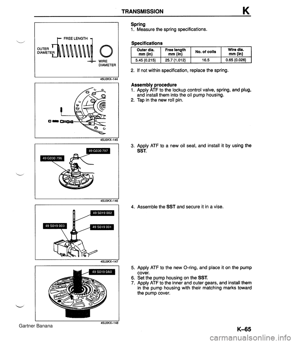
TRANSMISSION K WIRE DIAMETER Spring 1. Measure the spring specifications. Soecifications I Outer dia. I Free Ienpth I cO1ls I :Ired$ mm {in) mm {in) I 2. If not within specification, replace the spring. Assembly procedure 1. Apply ATF to the lockup control valve, spring, and plug, and install them into the oil pump housing. 2. Tap in the new roll pin. 3. Apply ATF to a new oil seal, and install it by using the SST. 4. Assemble the SST and secure it in a vise. 5. Apply ATF to the new O-ring, and place it on the pump cover. 6. Set the pump housing on the SST. 7. Apply ATF to the inner and outer gears, and install them in the pump housing with their matching marks toward the pump cover. Gartner Banana
Page 506 of 1708
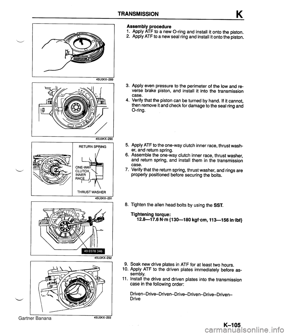
TRANSMISSION K Assembly procedure 1. Apply ATF to a new O-ring and install it onto the piston. 2. Apply ATF to a new seal ring and install it onto the piston. 3. Apply even pressure to the perimeter of the low and re- verse brake piston, and install it into the transmission case. 4. Verify that the piston can be turned by hand. If it cannot, then remove it and check for damage to the seal ring and O-ring. 5. Apply ATF to the one-way clutch inner race, thrust wash- er, and return spring. 6. Assemble the one-way clutch inner race, thrust washer, and return spring, and install them in the transmission case. 7. Verify that the return spring, thrust washer, and rings are properly positioned before securing the bolts. RETURN SPVING THRUSTWASHER 45UOKX-291 8. Tighten the allen head bolts by using the SST. Tightening torque: 12.8-1 7.6 N-m (1 30-180 kgfacm, 11 3-156 in-lbf) 9. Soak new drive plates in ATF for at least two hours. 10. Apply ATF to the driven plates immediately before as- sembly. 11. Install the drive and driven plates into the transmission case in the following order: Driven-Drive-Driven-Drive-Driven-Drive-Driven- Drive Gartner Banana
Page 510 of 1708

TRANSMISSION K 8. Apply ATF to the new O-rings, and install them onto the manual shaft. 9. Apply ATF to the manual shaft, and install it into the transmission case. 10. Install the parking rod and retaining ring. 11. Apply ATF to the manual plate, and install it onto the manual shaft. 12. Drive the spring pin. 13. Check the parking mechanism operation. 14. Apply ATF to the new seal rings, and install them onto the oil distributor. 15. Install the snap ring, key, and speedometer drive gear onto the output shaft. 16. Secure the speedometer drive gear with the snap ring. Gartner Banana
Page 593 of 1708
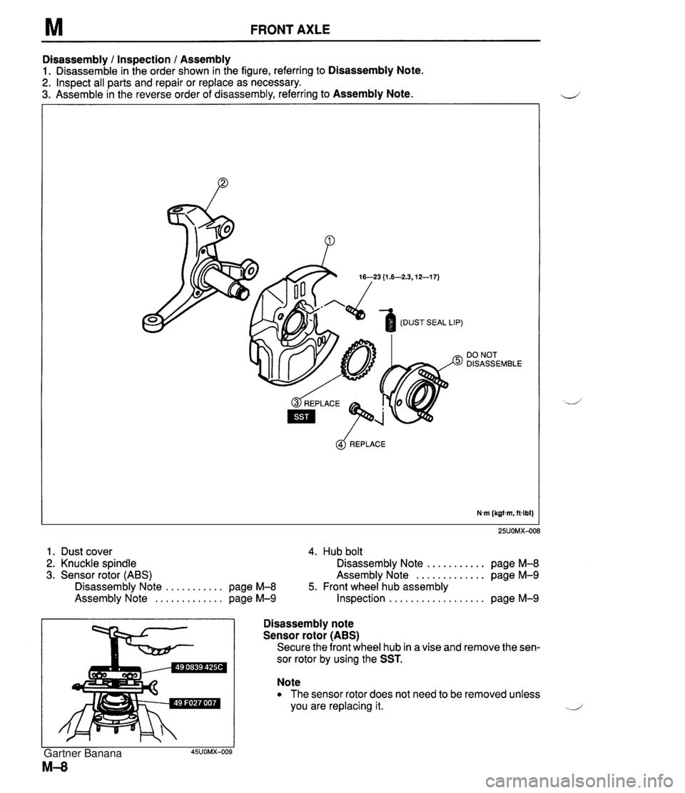
M FRONT AXLE Disassembly 1 Inspection 1 Assembly 1. Disassemble in the order shown in the figure, referring to Disassembly Note. 2. Inspect all parts and repair or replace as necessary. 3. Assemble in the reverse order of disassembly, referring to Assembly Note. DO NOT DISASSEMBLE @$ REPLACE N.m (kgfm, ftdbf} 1. Dust cover 4. Hub bolt 2. Knuckle spindle Disassembly Note ........... page M-8 3. Sensor rotor (ABS) Assembly Note ............. page M-9 Disassembly Note ........... page M-8 5. Front wheel hub assembly Assembly Note ............. page M-9 Inspection .................. page M-9 Disassembly note ' Sensor rotor (ABS) I Secure the front wheel hub in a vise and remove the sen- sor rotor by using the SST. Note The sensor rotor does not need to be removed unless you are replacing it. ..-.' Gartner Banana
Page 619 of 1708

M DIFFERENTIAL Disassembly note Output shafts Remove the output shafts with two pry bars as shown in the figure. -J Differential case Caution The differential case is made of aluminum, and is therefore easily dented and scratched by metal tools. When. separating the differential carrier from the case, use only a plastic hammer at the point shown in the figure. Strike the differential carrier with a copper hammer to separate it from the case. Differential gear assembly Mount the differential gear assembly on the SST. Bearing caps Mark one bearing cap and the carrier. Adjusting nuts Mark one adjusting nuts and the carrier. Knock pin Secure the gear case in a vise and tap out the knock pin toward the ring gear side. Bearing inner races (Side bearing) Note Mark the bearings so that they can later be reinstalled in the same position. Remove the bearing inner races (side bearing) from the gear case by using the SST. -1 Gartner Banana
Page 622 of 1708
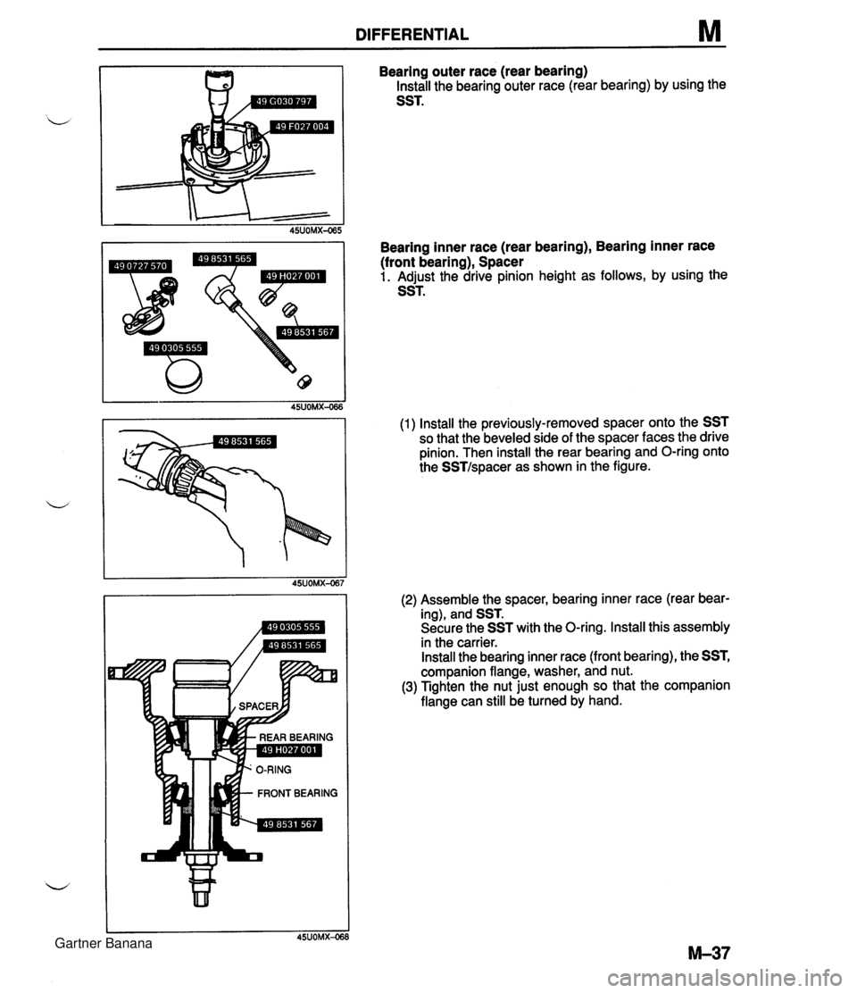
DIFFERENTIAL M Bearing outer race (rear bearing) Install the bearing outer race (rear bearing) by using the SST. Bearing inner race (rear bearing), Bearing inner race (front bearing), Spacer 1. Adjust the drive pinion height as follows, by using the SST. (1) Install the previously-removed spacer onto the SST so that the beveled side of the spacer faces the drive pinion. Then install the rear bearing and O-ring onto the SSTIspacer as shown in the figure. (2) Assemble the spacer, bearing inner race (rear bear- ing), and SST. Secure the SST with the O-ring. Install this assembly in the carrier. Install the bearing inner race (front bearing), the SST, companion flange, washer, and nut. (3) Tighten the nut just enough so that the companion flange can still be turned by hand. Gartner Banana
Page 625 of 1708

M DIFFERENTIAL Thrust washers (Standard) 1. Adjust the backlash of the side gears and pinion gear as follows. (Standard) (1) Set a dial gauge against the pinion gear as shown. ,+, (2) Secure one of the side gears. (3) Move the pinion gear, and measure the backlash at the end of it. If not within specification, replace the dif- ferential gear as an assembly. ("TORSEN" LSD) Standard backlash: 04.1 mm (0-0.004 in) (4) If the backlash exceeds the standard, use the select- able thrust washers for adjustment. 2. Install the new knock pin to secure the pinion shaft. Stake the pin with a punch to prevent it from coming out of the case. Thrust washer thickness: 3. Apply thread-locking compound to bolt threads @ and points @I of the gear back face. Apply approximately 0.04 cm3 I0.04 cc, 0.0024 cu in} of thread-locking com- pound at each point and bolt thread. 4. lnstall the ring gear onto the gear case. Identification mark 0 0.5 1 1.5 2 Tightening torque: 69-83 N.m (7.0--8.5 kgf-m, 51-61 ft-lbf) Thickness 2.00mm i0.0787 in} 2.05mm (0.0807 in) 2.10mm {0.0827 in) 2.15mm (0.0846 in} 2.20mm i0.0866 in} 5. Press the bearing inner races (side bearing) on by using the SST. 6. Install the differential gear assembly in the carrier. 7. Note the identification marks on the adjusting nuts, and install them on their respective sides. 8. lnstall the differential bearing caps, making sure that the identification mark on the cap corresponds with the one on the carrier by using the SST. Then temporarily tighten the bolts. Gartner Banana