battery MAZDA MX-5 1994 Workshop Manual
[x] Cancel search | Manufacturer: MAZDA, Model Year: 1994, Model line: MX-5, Model: MAZDA MX-5 1994Pages: 1708, PDF Size: 82.34 MB
Page 1068 of 1708

u TROUBLESHOOTING Step 3 1. Turn the ignition switch to ON. 2. Turn off the fan switch and ACS. 3. Measure the voltage at the terminal-wires of the resistor. u B+: Battery positive voltage I Terminal I Voltage I Action A (1-pin connector) A B C Step 4 1. Turn the ignition switch to ON. 2. Turn the fan switch to the fourth position. 3. Measure the voltage at the G terminal wire of the fan switch connector. .J B+: Battery positive voltage B+ , Other D CheckA terminal Replace blower motor B+ Other B+ Other B+ Other Step 5 1. Turn the ignition switch to ON. 2. Turn off the fan switch and ACS. Check B terminal Replace resistor Check C terminal Replace resistor Check D terminal Reolace resistor B+ Other Terminal G 3. Measure the voltage at the terminal-wires of the fan switch connector. Go to Step 4 Replace resistor B+: Battery positive voltage - Voltage B+ Other Action Repair wiring harness (Fan switch - GND) Go to Step 5 Gartner Banana
Page 1069 of 1708

TROUBLESHOOTING u 7- Symptom: Magnetic clutch does not operate I Normal operation of magnetic clutch The PCME controls the operation of the condenser fan and magnetic clutch, depending on engine load. (Refer to section F.) The magnetic clutch is supplied with battery positive voltage as follows: 1. The ACS and fan switch are turned on. 2. The PCME receives a signal that the ACS and fan switch are on and creates a ground circuit. 3. The A/C relay is magnetized and the contact is closed. 4. Battery positive voltage is applied to the magnetic clutch and the clutch locks. WIPER 20A AD FAN 20A FUSE BLOCK MAIN FUSE BLOCK Step 1 1. Check the following fuses. I Fuse I Amperage I Location I I I . - I WIPER I 20A 1 In fuse block I I AD FAN I 20A 1 In main fuse block I 2. If the fuses are OK, go to Step 2. 3. If a fuse is burned, check for a short circuit in the harness before replacing it. Step 2 1. Run the engine at idle. 2. Turn on the ACS and fan switch. 3. Measure the voltage at the A terminal wire of the mag- netic clutch connector. B+: Battery positive voltage I Terminal I Voltage I Action 1 Step 3 1. Start the engine. 2. Turn on the fan switch and ACS. 3. Measure the voltage at terminal C and A of the A/C relay connector. B+: Batterv positive voltaae - -- A 1 Terminal I V0lta0e 1 Action I I C I Other I Repair wiring harness (AD FAN 20A fuse - AIC relay) I B+ Other I 1. -. B+ I GO to step 4 Replace magnetic clutch Go to Step 3 I A 1 Other I Repair wiring harness (WIPER 20A fuse - AIC relay) I Gartner Banana
Page 1070 of 1708

u TROUBLESHOOTING Step 4 1. Remove the relay. 2. Apply battery positive voltage and check for continuity between the relay terminals. B+: Battery positive voltage 0---0 : Continuity I I I 45U0UX-013 3. If correct, repair wiring harness (AC relay - magnetic clutch). 4. If not as specified, replace the A/C relay. 1 0 10 I I I 2 1 B+ 1 GND 1 0 I Gartner Banana
Page 1071 of 1708

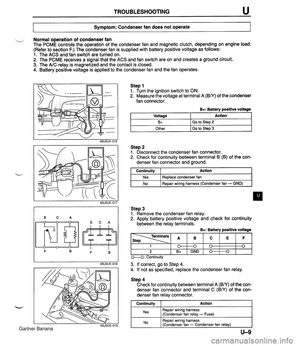
TROUBLESHOOTING u Symptom: Condenser fan does not operate Normal operation of condenser fan The PCME controls the operation of the condenser fan and magnetic clutch, depending on engine load. (Refer to section F.) The condenser fan is supplied with battery positive voltage as follows: 1. The ACS and fan switch are turned on. 2. The PCME receives a signal that the ACS and fan switch are on and creates a ground circuit. 3. The A/C relay is magnetized and the contact is closed. 4. Battery positive voltage is applied to the condenser fan and the fan operates. Step 1 1. Turn the ignition switch to ON. 2. Measure the voltage at terminal A (B/Y) of the condenser fan connector. B+: Battery positive voltage Step 2 1. Disconnect the condenser fan connector. 2. Check for continuity between terminal B (B) of the con- denser fan connector and ground. Voltage B+ Other I GO to step 3 Action Go to Step 2 I continuity I Action I Step 3 1. Remove the condenser fan relay. 2. Apply battery positive voltage and check for continuity between the relay terminals. B+: Battery positive voltage Yes No Replace condenser fan Repair wiring harness (Condenser fan - GND) M: Continuity - - - 3. If correct, go to Step 4. 4. If not as specified, replace the condenser fan relay. 1 0 2 B+ Step 4 Check for continuity between terminal A (BN) of the con- denser fan connector and terminal C (BN) of the con- denser fan relay connector. I Continuity I Action 1 Repair wiring harness (Condenser fan relay - Fuse) B 0 GND I Repair wiring harness (Condenser fan - Condenser fan relay) I C 0 0 E 0 F 0 Gartner Banana
Page 1098 of 1708

u AIR CONDITIONER CONDENSER FAN Removal / Installation 1. Disconnect the negative battery cable. 2. Disconnect the cooling fan and condenser fan connector. 3. Remove the bolts. 4. Remove in the order shown in the figure. 5. Install in the reverse order of removal. 1. Cooling fan 2. Condenser fan Inspection 1. Disconnect the condenser fan connector. 2. Verify that the condenser fan motor runs when connect- ing battery positive voltage to terminal A and grounding terminal B. B+: Battery positive voltage u 45UOUX-082 U-36 Motor operation Yes Connection B+ A GND B Gartner Banana
Page 1099 of 1708

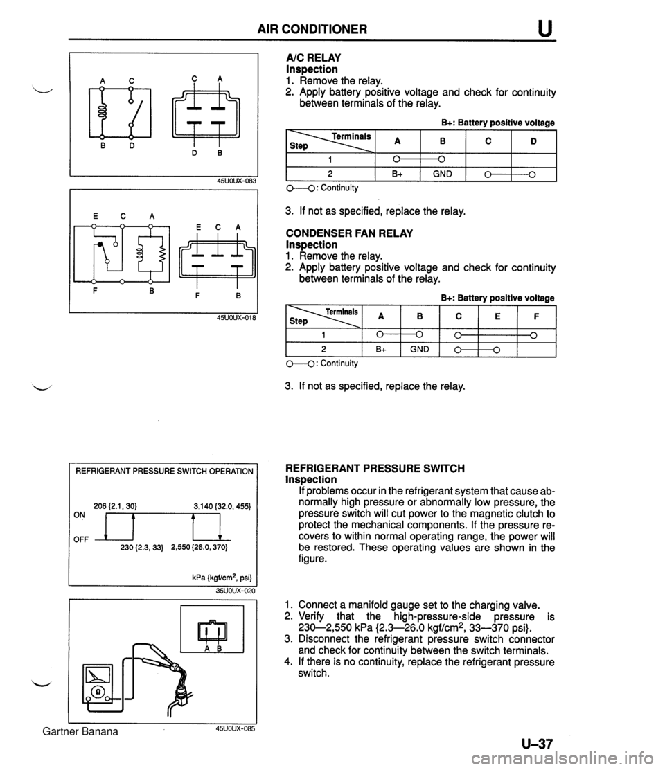
AIR CONDITIONER REFRIGERANT PRESSURE SWITCH OPERATION 206 {2.1,30) 3,140 (32.0, 455) OFF ON n 230 {2.3,33) 2,550 (26.0,370) A/C RELAY Inspection 1. Remove the relay. 2. Apply battery positive voltage and check for continuity between terminals of the relay. B+: Battery positive voltage 3. If not as specified, replace the relay. CONDENSER FAN RELAY lnspection 1. Remove the relay. 2. Apply battery positive voltage and check for continuity between terminals of the relay. B+: Battery positive voltage 1 2 O--(): Continuity 3. If not as specified, replace the relay. 0 B+ 1 2 REFRIGERANT PRESSURE SWITCH lnspection If problems occur in the refrigerant system that cause ab- normally high pressure or abnormally low pressure, the pressure switch will cut power to the magnetic clutch to protect the mechanical components. If the pressure re- covers to within normal operating range, the power will be restored. These operating values are shown in the figure. kPa (kgf/cm2, psi) 35UOUX-020 1. Connect a manifold gauge set to the charging valve. 2. Verify that the high-pressure-side pressure is 230-2,550 kPa (2.3-26.0 kgf/cm2, 33-370 psi). 3. Disconnect the refrigerant pressure switch connector and check for continuity between the switch terminals. 4. If there is no continuity, replace the refrigerant pressure switch. 45UOUX-085 0 GND 0 B+ 0 0 GND 0 0 0 0 3 Gartner Banana
Page 1277 of 1708

CONSTRUCTION No. @ I Rear deck panel @ @ - - 1 8 1 Quarter panel Part Name @ I Rear deck member Trunk lid Rear end panel I @ 1 Light housing No. Part Name @ Q @ I Tunnel gusset Seal plate Splash protector @ @ I @ I Rear fender panel Bulkhead panel Floor side panel Floor center pan 0 I Crossmember No. 4 @ @ I @ I Door body @ Q Rear fender gusset Rear fender rain rail Fuel filler lid Parking bracket Crossmember No. 3 8 1 Floor side plate @ @ I @ / Side sill, inner B @ @ I ~ut plate Rear fender, lower Trunk board bracket Tank floor pan assy Trunk floor assy 1 8 1 Side sill reinforcement Q @ 0 I Rear side frame Striker reinforcement Side sill, inner C I I I 1 8 ( Cowl side panel @ @ I Closing bracket I @ I Hinge pillar Floor side panel @ @ 8 1 Battery clamp bracket I @ I Side sill, inner Side sill, outer Bumper bracket Cap bracket @ I Corner junction 1 8 1 Front header, Q @ @ @ Side sill gusset Hinge pillar, outer Side panel, inner Wheel inner house @ @ @ Beltline reinforcement Front pillar, outer Front pillar, inner @ Front header, upper Gartner Banana
Page 1411 of 1708

1850 BATTERY I 1850 -1 B! BATTERY ATTERY 46AZQLtS) PANASONIC LAMP, BATTERY RACKET, BATTERY CLAM 'RAV BATTERY Gartner Banana
Page 1697 of 1708

ALPHABETICAL INDEX *a* ENGLISH S** - BELTtA1(L) ,FRT BELt'A1(R),FRT SEAT------ BOLT,JACK SET------------ BELTtB'(R),FRT SEAT------ BOLT,LAMP LID------------ BELTIB1,FRT SEAT--------- BELTlVl------------------ 1-05 2-KB BKACKETJCOUPLER-KNOCK SEN BHACKET,CRASH PAD-------- BRACK~T,E~G.K.PIPE------- BRACKET,FENDER----------- *********Y******* * * * A * * * **#*~******%***** ACTUATOR,A.C.C.---------- 2-Jl3 ACTUATOR, SHIFT LOCK---- -- 1-616 ADAPTERIDRIVE PLATE------ 1-J7 ADJUSTER NO .J-----.----- -- 2-M8 ADJUSTER N0.4------------ 2-M8 AGJUSTER,HYDRAULIC LASH-- 1-N3 ADJUSTER,NO.1------------ 2- J8 ADJUSTER,N0.2------------ ALTERNATOR--------------- 2-J8 1-C7 ANCHOR UNIT(L),BE?T------ 2-39 ANCHOR UNIT(R1,BELT------ 2-D9 ANTENNA,RADI3------------ 2-~141 ANTILOCK BRAKE----------- 1-N15 ARM NO.1, LINK------------ 2-H15 ARM N0.2,LINK------------ 2-115 ARM(L1,LOWER------------- 1-113 ARM(L),LOWER-REAR-------- 1-F12 ARM(L1,UPPER------------- 1 -H13 ARM(R),l.OWER------------- 1-H13 ARM(R),LOWER-REAR-------- 1-F121 ARM(R),UPPER------------- 1-H13 ARM,UPPFR-FRT------------ 1 -HI31 ARM.UPPER-REAR----------- 1-F121 - 1-~6 BEZEL(L1,HEAD LAMP------- 2-M3 BEZEL!"),HEAD LAMP------- 2 -M3 BLADE(d>,WIPER-FRONT----- 2-H15 BLADE WIPER-FRONT--------- 2-H15 BLOCK,CYLINDER----------- BLOCKIFUSE--------------- 1 -H3 2-614 BLOCK,MAIN FUSE---------- BLOWER UNIT-----.-------- 2-114 2-Fll BODY 8 PISTON(L),CALIPER- 1-F11 > -fit v BUSHlNG,RUBBER-LOWER ARM- A-LTAJ BODY & PISTON(R),CALIPER- 1-FS1 1-613 BODY(L),FRONT DOOR------- 2- J9 BODY(R),FRONT DOOR------- 2-J9 BODY,CONTROL VALVE-UP---- 1 -GB BODY,LOW-RADIO ANTENNA--- 2-El4 BODY,THROTTLE------------ 1 -K4 BODY.VALVE LWR----------- 1 -18 BRACKET,MEMBER----------- 2-J7 BRACKET.PARKING CABLE-FLO 2-K5 i-Miii SRACKET~STARTER----------- 1-~6 BRACKETISTOPPER-3kTTERY-- 1-i7 BRACKET,VANE PUMP-------- 1-C13 BRACKET, WASHER TANK ------ 2-C15 2-F15 BRACKET,WIRE CLIP-OXYGEN- 1-F3 BRACKET,WIRING----------- 2-H14 BREATHER---.-------------- 2-114 1-ti11 1 -L7 1-111 BRE/tTHER,AIR-T/MISSION--- 1-D6 BRKT(!i,BUMPER-RR SKIRT-- 2-L5 BdKT(L1,SEAT-F.FLOOR PAN- 2-L5 BRKT(L),TRK.BOARD-FENDER- 2-J5 BRKT(R),BUNPER-RR SKIRT-- 2-L5 BF!KT(R) ,SEAT-F. FLOOR PAN- 2-K5 BRKT,AIR CLNR-WHL APRON-- 2-C5 BRKT,BATT.CLANP-QTR PANEL 2-05 BRKT ,CAP-QUARTER PANEL--- 2- I5 BRKT,DIAGNOSlS UNIT------ 2-H13 BRKT,DIAGNOSIS/POWER UNIT 2-H13 BRKT,MOTOR-ANTENNA------- 2-El4 BRKTtA1,WASHER TANK-FRT-- 2-El5 BRUSH-.------------------- 1 -C7 1 -F7 BRUSH ,YOKE-- - - - - - --- - - - - -. 1-F7 BuLa--------------------- 1 -H7 2-C4 2-C7 2-D4 2-F.4 2-67 2-H4 2 -H7 2 - L 7 BULn 8 SOCKET------------ 2-L7 BUL0,MODE CONTROL-------- 2-El 1 BULB,RESISTOR------------ 2-C7 2-67 BULB'Bt,SWITCH-RR DEFOGER 2-El3 BUMPER, FRONT - --- - . -- -. .. - - BUMPER, REAR- - - - - - - - - - - - - - 2 - E3 2-H3 BUSH---------.----------- 1-1115 1-616 1 - r; 1 tl 1 - .I6 1 -Ll4 - .-.- - L A1 BRACKET------------------ 1 -LIB 1-K7 1-1.15 2-C15 2-G14 2-H141 2-L5 BRACKET NO 1,k.B.S.------ 1 -MI 5' BRACKET ~0.5,A.B.S.------ 1 -M! 5 BRACKET(L),CABLE--------- 1-GI1 BRACKET(L1,ENGINE-------- BRACKET(L),F. BUMPER SIDE 2-F3 BRACKET(L),FRONT-AUDIO--- BRACKETCL) ,HINGE-LAPP LID 2-M3 BRACKETfL),IHST.--------- 2-F5 BRACKET(L1,TUNER--------- BRACKET(L),RADTATOR------ 2-N4 BRACKET(L),STARILIZER---- 2-D5 2-N13 RRACKET(R),CABLE---------- 1 -Gll NRACKET(R),ENGINE-------- i l-cl41 BRACKET(P),FRONT-AUDIO--- BRACKET(R),HIHGE-LAMP LID 2-M3 IRAcKET(R),INsT.--------- 2-M131 2-F5 BRACKET(R1,RADIATOR------ 2-N4 I BRACVET(R),STARILIZER---- 2-C5 I bRACKET(R) ,TUNER--------- 2-N13 BRACKET(RR),AUDIO-------- 2-N131 BRACKET,ACCEL WIRE------- 1-04 BRACKET ,ACTUATOR--- - ----- 2-~131 BRACKET,ACTUATOR-P.C.C.-- 2-313 RRACKET,ACTUATUR-FRONT--- 2-J13 RRACKET,AIR CLEPAER------ 1-14 1 BRACKET,BATTERY CLAMP---- 1-17 BKACKET,BUHPER---- ------- 2-N4 I BRACKET,CAHISTER-- .--- .. - 1-F4 BRACKET,CLAMP------------ 2-1111 BRACKET ,CLIP ------ 2 - L 3 BRACKET,COMPRESSOR------- 1-65 1 BRACKE1,CONTROL UNIT- .--- 1-Cl5 2-C13' BRACKET,COUPLER----- ----- 1-1112' ... - - .- - --.A- €-001 BACK(L1,FRONT SEAT------- 2-C9 I BACK(R),FRONT SEAT----- -- 2-1 A BAG,TOOL----------------- 2-MB / 2-Dl6 BALL JOINT,LOWER--------- BALL, S'TEEL - - - - - - - - - - - - - - - 1-113 1-El4 1 -H7 BAUD--------------------- 1-Dl41 CAP SET,KESERVE TANK----- 1 -I 131 BOLT,AIR CLEANER--------- 1-14 BOLT,AIR C0K.------------ 2-Jll BOLT,ANCHOR END---------- 1.M7 BOLT,BAFFLE PLATE-------- 1 -K7 dOLT,BEARING CAP--------- 1 -H3 BOLT,CAMSHAFT CAP-------- 1-E3 BOLT,CARRIER------------- 1 -K11 ~OLT,CL&MP--------------. 1-14111 1-17 BOLT .COMPRESSOR---------- 2-1111 BOLT,COEPRESSOR-AIR CON.- 2-Kll BOLT,CONNECTOR----------- 1-~151 1-615 BEARlNG,BALL------------- 1-66 ! BFARING.BALL-ALT. FRONT- - 1 -C7 I BEARING~BALL-ALT. REAR--- 1-ci I REARING, BALL-COUNTER SHAF 1 -G6 I BEARING~BALL-FLY WHEEL--- BEARING,RALL-MAIN DRIVE G BEARING,BALL-MAI!i SHAFT-- BEARING,IIEEDLE----------- CA?,TOP LOCK---------.--- CAP,VANE PUMP TANK------- CARRIER,DlFFERENTIAL----- BOLT ]CONTROL VALVE------- 1-C8 I 1 -E8 1-KB I !!7LT,CROSS MEMBER-------- 2-C5 I BOL1,CYLINDER HEAD------- 1-E3 ' BOLT.UECK LOCK----------- 2-112' 1-LIZ; BEAR1NCi.WtiEEL--------- ---- 1-El11 BELT TIMING------ 1-NJ ! .. . CAT . AUNAOS - U3 Gartner Banana
Page 1698 of 1708

ALPHABETICAL INDEX *%* ENGLISH *** CASE,T/MISSlON------------ CASE'A' , LLOWER UNIT- ----- CASE'A',COOLING UNIT----- CASE'A1 ,HEATER UNIT------ CASEIB' ,BLOWER UNLT------ CASE'B' ,COOLING UNIT----- CASE'B9,HEATER UNIT------ CASE'OUT',ASHTRAY-------- CASING,DIFFERENTIAL------ CASING,HYDRAULIC UNIT---- CASING,STOPPER----------- CATALYST ,THREE WAY------- CEILING,TOP-----.--------- CHANNEL( L) DIVISION-DOOR- CHANNEL(R)lDIVISION-DOOR- CHECKER,DOOR------------- CLAMP---------.-..--------- CLAMP,BATTERY------------ CLAMP,HOSE--------------- 1-L11 DRUM,CLUTCH-------------- 1-N8 DRUM,CONNECTING---------- 1 -H9 DRUM,DIRECT------------.- 1-F9 DRUMIREAR CLUTCH------ -- 1-C9 DUCT(L)---------------..-- 2-DB DUCT(L1 ,SIDE DEMI .-- .---- DUCT(R)----..------------- 2-C8 2-DB DUCT(R1,SIDE DEMT,------- DUCT,AIR- ---- ------------ 2-C8 DUCT,CENTER-------------- 2-Cll 2-C8 DUCTIFRESII AIR----------- 1-14 CLIP,WEATHLRSTRIP-OUTER-- 2-El1 CLIPtA',SPEEDOMETER CABLL 2-F7 CLIPIA',WEATHERSTRIP-OUT- 2-El1 CLIPIB',WIRE-BONNET------ 2-E5 CLGTH,REPAIR-TOP-------..- 2-Dli CLAMt3,HOSE-A 1 .P. /A. CLNR CLAMP,WATER HOSE--------- ELEMENTIAIR CLEANER------ 1-J4 EMBLEM,CAP-WIiE€I.--------- 1-Ll;? END,CONTROL LEVtR-------- 1 -K6 ENDlS/ROD<1ST82ND)------- 1-J6 ENl)rS/ROD(3RDB4TH;------- 1-J6 ENG:SHIFf ROD(O/TOI'&REV.) 1-K6 ENGINE,PARTIAL----------- ENGINE,SHORT------------.- 1-D3 ESCUTCHEON--------------- 1-D3 EVAPORATOR--------------- 2-ti9 2-Mll EYE BOLT K?T,31. GEAR---- 1-M12 2-116 2-L12 2-N5 COVER,5OIE-CC1----------- 2-Ki COVER,HOLE-ANTENNA------- 2-El4 COVER,HOLE-LIFT GATE----- 2-Dl0 COVER,INNER HANDLE----.--- 2-M9 COVER,INTERIOR MIRRORm--- 2-F16 COVER,JOINT-LOWER-------- 1-112 COVER,JOINT-UPPER-------- 1-112 COVER,LEVER-OPENER------- 2-L7 COVER,MAIN FUSE BLOCK---- 2- I1 4 COVER,OIL PUMP----------- COVER,REAR--------------- 1-N4 1-J3 1-K12 COVEK,RE&R-ALTERNATOR---- 1-C7 CQVER,RELAy------------..- 2-H1! COVER,ROD---------------- 1-1.6 COVER,SELECT LEVER------- 1-616 COVERISERVICE HOLE------- Z-F5 COVER,SERVO-------------- COVER,SIDE--------------- 1-N7 2-K7 COVERISPARE TIRE--------- 2-Cl6 COVER,l'HERHO------------- 1-D5 CQVER,THERMOSTAT--------- 1-D5 COVER,TIMING EELT-C. ----- 1-13 GASKET------------------- 1-C5 1-C15 1 -F3 1-H7 1-J14 1-L4 1 - L 14 1-N7 2- ~4 GASKET 8 SEAL KIT-------- 1-M9 GASKET KIT,COMPRESSOR---- 2-K11 GASKET SET ,CYL HEAD----- i -D3 GASKET SETIENGINE-------- 1-DY GASKET(C1 ,TIMING BELTCL) - 1-13 GASKEl'(INN),TIHIHG BELTCL 1-13 BASKET(L)---------------- GASKET,CAP--------------- 1-13 1-114 GASKETICONPRESSOR-------- 2-K11 GASKET,CONVERTER--------- !-Dl4 G0.SKET ,COVER PLATE------- 1-K6 GASKET,CYl.INDER WEAD----- 1-F3 GASKET,DRAIN PLUG-------- 1-li14 GASKETIDRUM SUPPORT- ----- 1 - D8 CASKET.E.G.R. VALVE------ 1-L4 CORD NO.1,HI.TENSION----- 1 -M6 CORD NO.2.HI.TENSION----- 1 -M6 CORD NO.~;HI.TENSION----- 1 -M6 CORD NU.4,HI.TENSION----- 1 -M6 CORD SET,HI.TENSION------ 1 -M6 CORa,EARTH--------------- 2-c14 2-Nl:! CORE,HEATER Ub!IT--------- 2-Dl1 COTTER,VALVE-IN.--------- 1 -N3 COUPLERISOLENOID VALVE--- 1-E0 COVER-------------------- l-Cl6 2-C6 COVER NO.l,ADJ-FRT------- 2-66 COVER NO.2,ADJ-FRT-a+----- 2-60 COVER N0.3.ADJ-FRT------- 2. SC COVER(C),SENSOK---------- 2-H9 COVER(L),BELT LINE------- 2-Kli COVER(L).BRACE BAR------- 2-C6 COVER,UNDER-------------- 2-C6 COVER,VALVE BODY--------- 1-10 COVER,WASHER TANK-------- 2-F1E COVER,WHEEL CORE--------- 1-Hli COVER, WIPER ARM-FRONT--- - 2-H15 COVER'L1,HYDRAULIC UNIT-- 1-Ml5 COWLING,RADIATOR--------- CRANKSHAFT--.. -- ------ ---- 1-E5 1 -K3 CUPISECONDARY------------ 1-H15 CUSHION(L),FRT SEAT------ 2-N8 CUSHIOW(R),FRT SEAT------ 2-K8 CUSHION,LID HINGE-------- 2-H4 CUSHION.RUBBER----------- 2-17 2-Ll CYL.,CLUTCH MASTER------- I -El4 CYL.,CLUTCH RELEASE------ 1-El4 CYL,,TAHDEM MASTER------- 1-F15 1-61 5 1-H15 /~ASKET;EX.MANIFOLD------- 1-E4 GASKET,EXH.PIPE-CONVERTER 1-Dl4 GASKET,EXTENSION--------- 1-C8 GASKET,FILLER PIPE------- 1-H14 GASKET ,FRONT COVER--- .--- I-C6 GASKET,HEAD COVER-------- 1-fi3 GASKET,IN.MANIFOl.D------- 1-D4 GASKET.LICENSE LAMP------ 2-H4 COVER( L) ;DECK LOCK------- 2- Jli COVER(I.),DRAIN-SOFT TOP-- 2-Hli COVER(L),DUST------------ 1-El2 1-Fl? COVER(L),HINGE----------- 2-D9 COVER( L) ,HOLE----------- - 2-Nl! COVER(L),KNUCKLE--------- 2-NB COVER(L).SEAT BACK------- 2-N8 - ... CLIP SET,DRlVE SI!AFT----- 1-DlI CLIP(L1 ,FORM PLATt .------ 2-El2 CLIP(R),FORM PLATE------- CLIP,CABiE--------------- 2-El2 1-Dl6 CLIP ,ENGINE HARNESS------ 2-N141 CLIP,FLEXIBLE Hi3SE------- 1-C16' l-~ld I-Ml5 2-1314 FASTENER SET ,TOP CLOTH--- 2- Dl2 FASTENER,BONNET RELEASE-- 2-KG FASTENER,DOOR TRIM------- 2-rl0 2-#7 GASKET,OIL PUMP---------- 1- J7 GASKET ,OIL STRAINER-- ---- 1-C5 1-rJ4 GASKET.RR.COH0.---------- 2-F4 1-1jsl CQv~~(~);S~~so~-l-------- 2-H9 I I-K~SI COVER( L) ,SENSOR-AIR BAG-- 2-H9 CLIP,HAHNESS------------- 2-E15: COVER(R),REL'I LINE------- FKl4 2-G13! COVER(R),BRACE BAR------- 2-C6 , 2-M14' CUVER(W),DECK LOCK------- 2-1121 2-N14( COVERIR) ,DRAIN-SOFT TOP-- 2-HIZi CLlP,HARNESS-HAND BRAKE-- 2-M7 I COVERCR) ,DUST.----------- 1-E13i CLlP,HEATER COtITKOL--- - -- 2-Elli 1-F131 CLIP, HOSE- SUB T.8 VATFR H 1 -F5 i COVER(R) ,HINGE- ---------- 2-C9 ! CLIP,OIL FJPE-------. ---- 1-L7 I CLIP ,PIPE--- -..- ---------. 2-N8 j I-El6: COVER(R),HOLE------------ Z-N1S1 x-~I(+ COVER(RI,KNUCKLE--------- 2-18 I 1-Fl6, COVER(R) ,SEAT BACK------- 2-K8 I FASTEHERILIFT GATE TRIM-- 2-F14 FASTENERBRAIN RAIL-REAR-- %-Eli FASTEHER; RAIN FASTENER. REAR 1 SIDE TUXN- - .SPRANG CAP- FASTEYER,SEEL------------ 1- J3 1-K4 FASTENER, STOP LAMP-HI . --- II D f FEEDER-ANTENNA- - - - - -- - - - - 2-F14j GASKET~VAC POWER ASSIST- !-El5 I )t s FILTER ,AIR--------..------ 2 - N 12 1-G15 FILTER, FUEL- - ..- - - - - - ----.. ~%*t*~x*rfi**tf%%w 1-F4 1 SASK6T.W.PUMP INLET------ 1-D5 I FII.TEP,FUEL PUMP--------- 1-H14 GASKET,WATER PUMP------ - 1-05 IlAl~,FRONT-WIND.---------- 2-~111 FINISHEPIWEAR------.----- 2-i4 GASKET,WINDOW REGULATOR-- 2-C10 . . . . . . . -. . . . . . -- .. - -- ------- L.- -.- --- -.-- CAT. AUNA04-03 F.-002 Gartner Banana