oil MAZDA MX-5 1994 Workshop Manual
[x] Cancel search | Manufacturer: MAZDA, Model Year: 1994, Model line: MX-5, Model: MAZDA MX-5 1994Pages: 1708, PDF Size: 82.34 MB
Page 737 of 1708

TROUBLESHOOTING GUIDE TROUBLESHOOTING GUIDE Problem General instabllity Body "rolls" "Heavy" steering wheel operation Steering wheel pulls to one side Excessive steering wheel play Body leans Abnormal noise from suspension system Shake (Steering wheel tibrates upldown) Shimmy (Steering wheel vibrates leftlright) Possible cause Weak coil spring Malfunction of shock absorber Worn or damaged stabilizer and/or suspension arm bushings Worn or damaged upper or lower arm ball joint Improperly adjusted wheel alignment Weak stabilizer Worn or damaged stabilizer and/or suspension arm bushings Insufficiently lubricated or stuck upper arm lower arm ball joint lmproperly adjusted wheel alignment Weak coil spring Worn or damaged stabilizer and/or suspension arm bushings Deformed upper or lower arm or knuckle Loose upper or lower arm bushing Worn or damaged upper or lower arm bushing Worn or damaged upper or lower arm ball joint Weak coil spring Weak stabilizer andlor suspension arm bushings Loose mounting component Poorly lubricated or worn upper or lower arm ball joint Malfunction of shock absorber Worn or damaged stabilizer and/or suspension arm bushings Excessive tire or wheel runout Loose lug nuts Unbalanced wheel@) Cracked or worn engine mounting rubber Cracked or worn steering gear mounting rubber Loose steering gear mounting bolts Stuck or damaged steering ball joint Excessive tire or wheel runout Loose lug nuts Unbalanced wheel(s) Insufficient tire pressure Unevenly worn tires Malfunction of shock absorber Loose shock absorber mounting bolts Stuck or damaged upper or lower arm ball joint Cracked or worn suspension bushings Damaged or worn front wheel bearing lmproperly adjusted front wheel alignment Action Replace Replace Replace Replace Adjust Replace Replace Replace Adjust Replace Replace Replace Replace Replace Replace Replace Replace Tighten Replace Replace Replace Replace Tighten Adjust or replace Replace Replace Tighten Replace Replace Tighten Adjust or replace Adjust Replace Replace Tighten Replace Replace Replace Adjust Page R-13 R-12,22 R-16, 18, 19, 23,24,25 section M R-15,17 R- 6 R-19,25 R-16, 18,19, 23, 24,25 section M R-15,17 R- 6 R-13 R-16, 18,19, 23, 24,25 R-15,17 section M R-16,18 R-16,18 R-15,17 R-13 R-16, 18, 19, 23,24,25 section M 7 R-15,17 R-l2,22 R-16, 18,19, 23,24,25 section M - section Q section Q section B section N section N section N - section Q section Q section Q section Q R-l2,22 R-12,22 R-15, 17 R-16,18,19 section M R- 6 15UORX-00 Gartner Banana
Page 738 of 1708

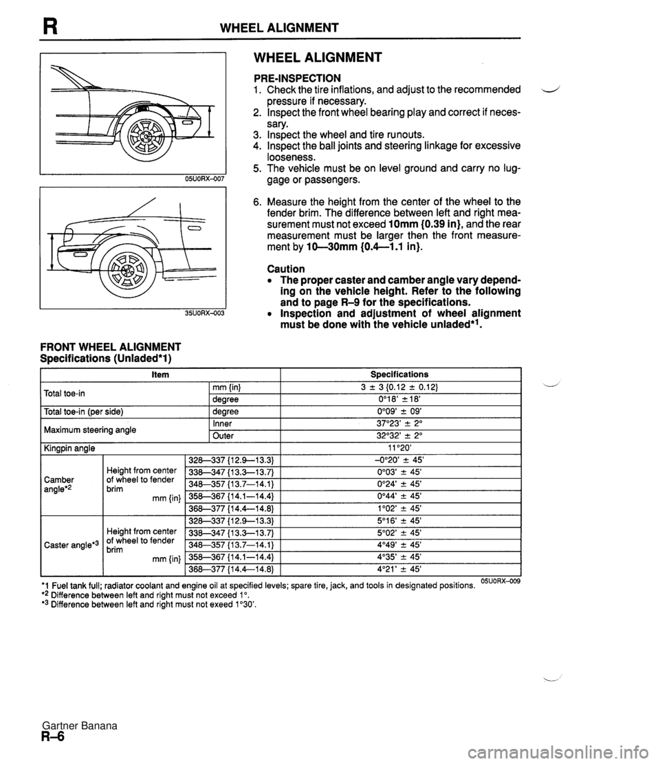
WHEEL ALIGNMENT WHEEL ALIGNMENT FRONT WHEEL ALIGNMENT Specifications (Unladed*l) PRE-INSPECTION 1. Check the tire inflations, and adjust to the recommended d pressure if necessary. 2. lnspect the front wheel bearing play and correct if neces- sary. 3. lnspect the wheel and tire runouts. 4. Inspect the ball joints and steering linkage for excessive looseness. 5. The vehicle must be on level ground and carry no lug- gage or passengers. 6. Measure the height from the center of the wheel to the fender brim. The difference between left and right mea- surement must not exceed 10mm (0.39 in), and the rear measurement must be larger then the front measure- ment by 10-30mm (0.4--1.1 in). Caution The proper caster and camber angle vary depend- ing on the vehicle height. Refer to the following and to page R-9 for the specifications. Inspection and adjustment of wheel alignment must be done with the vehicle unladed*'. . . I Y -- t~otal toe-in l~er side) I 1 dearee 0'09' + 09' I Total toe-in 3 2 3 I0.12 2 0.12) 0'1 8' 2 18' mm (in) dearee Maximum steering angle U - Inner Outer 11 '20' -0°20' 2 45' 0'03' ? 45' 0'24' 2 45' 0°44' -+ 45' 1'02' -+ 45' 5'1 6' ? 45' 5O02' -+ 45' 4O49' 2 45' 4'35' -+ 45' 4'21 ' -+ 45' I Kingpin angle 37"23' -+ 2" 32O32' 2 2" '1 Fuel tank full; radiator coolant and engine oil at specified levels; spare tire, jack, and tools in designated positions. OSUORX-009 ** Difference between left and right must not exceed lo. '3 Difference between left and right must not exeed 1'30'. 328-337 {I 2.9-1 3.3) 338-347 {I 3.3-1 3.7) 340-357 I13.7-14.1) 358-367 {I 4.1-14.4) 36&377 {I 4.4--14.8) 328-337 {I 2.9--13.3) 338-347 {I 3.3-1 3.7) 348-357 113.7-14.1) 358-367 {I 4.1-14.4) 368-377 {I 4.4--14.8) Camber angleg2 Caster angle*3 Height from center Of wheel to fender brim mm {in) Height from center Of wheel to fender brim mm (in) Gartner Banana
Page 741 of 1708

WHEEL ALIGNMENT REAR WHEEL ALIGNMENT Specifications (Unladed*) I Item I Specifications I L *' Fuel tank full; radiator coolant and engine oil at specified levels; spare tire, jack, and tools in designated positions. 05Uo~x-01~ *2 Difference between the leff and right must be exeed lo. 3 + 3 i0.12 * 0.12) 0'18' k18' 0'09' 2 09' -1 "08' +. 30' Total toe-in Total toe-in (per side) Camber angle'' LEFT WHEEL - mm {in) degree degree INCREASE I 1 346-355 (1 3.6-1 4.0) Height from center of wheel to fender brim'2 mm Iin) RIGHT WHEEL C INCREASE 356-3135 {14.0-14.4) 366-375 {I 4.4--14.8) 376-385 {I 4.8-1 5.2) 386--395 {I 5.2-1 5.6) LEFT WHEEL -C -0°54' r 30' -0'43' 2 30' -0°35' r 30' -0'30' +. 30' Toe-in Toe-in is adjusted by turning the front and/or rear adjust- ing cam bolts at the lower arm. Caution Adjust the toe-in before adjusting the camber. 1. Loosen the front and/or rear cam nuts. 2. Turn the front and/or rear adjusting cam bolts to provide the correct toe-in. I Counter- Counter- Decrease Clockwise Clockwise clockwise clockwise Toe-in Note Turning the front cam one graduation changes the toe-in about 2.8mm (0.11 in} and the camber about 15'. Turning the rear cam one graduation changes the toe-in about 2.8mm I0.11 in} and the camber about 6'. 3. 'Adjust the camber. Left wheel Camber Camber is adjusted by turning the front and rear cams at the lower arm. Right wheel Caution Adjust the camber after adjusting the toe-in. Front cam I Rear cam I Front cam I Rear cam 1. Loosen the front and rear cam nuts. 2. Turn the front and rear adjusting cam bolts the same amount in the opposite direction to provide the correct camber angle. Gartner Banana
Page 743 of 1708

FRONT SUSPENSION (DOUBLE-WISHBONE) FRONT SUSPENSION (DOUBLE-WISHBONE) PREPARATION SST 49 0727 575 Puller, socket oint Attachment, steering worm bearing preload measuring 49 GO34 1 A0 Compressor, coil spring Screw (Part of - 49 GO34 1 AO) - Wrench, flare nut For removal of lower arm ball joint For 1 49 GO34 101 49 01 18 850C Puller, ball joint For inspection of upper arm ball joint 49 H028 301 Installer, dust boot For 1 49 GO34 103 removal and installation of coil spring Body (Part of 49 GO34 1 AO) For removal and installation of brake pipe removal and installation of coil spring SHOCK ABSORBER AND SPRING Removal / Installation 1. Jack up the front of the vehicle and support it with safety stands. 2. Remove the undercover. 3. Remove the band for the wheel speed sensor harnes. 4. Remove in the order shown in the figure, referring to Removal Note. Arm (Part of 49 GO34 I AO) 5. Inspect all parts and repair or replace as necessary. 6. Install in the reverse order of removal. For removal of upper arm ball joint For installation of front lower arm boot For removal and installation of coil spring For removal and installation of coil spring 7. Loosely tighten the shock absorber, upper arm, stabilizer control link, and stabilizer bracket bolts. Tighten all other nuts and bolts to the specified torques. 8. Install the band for the wheel speed sensor. 9. Lower the vehicle. 10. With the vehicle unloaded, tighten the upper arm and shock absorber bolts to the specified torques. - 11. Adjust the front wheel alignment. (Refer to page R-6.) 25UORX406 Gartner Banana
Page 745 of 1708

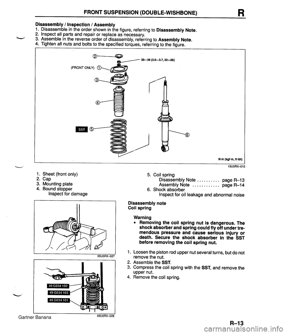
FRONT SUSPENSION (DOUBLE-WISHBONE) R Disassembly I Inspection I Assembly 1. Disassemble in the order shown in the figure, referring to Disassembly Note. 2. lnspect all parts and repair or replace as necessary. 3. Assemble in the reverse order of disassembly, referring to Assembly Note. 4. Tighten all nuts and bolts to the specified torques, referring to the figure. (FRONT ONLY) & 3 1. Sheet (front only) 2. Cap 3. Mounting plate 4. Bound stopper lnspect for damage 5. Coil spring .......... Disassembly Note page R-13 ............ Assembly Note page R-14 6. Shock absorber lnspect for oil leakage and abnormal noise Disassembly note Coil spring Warning Removing the coil spring nut is dangerous. The shock absorber and spring could fly off under tre- mendous pressure and cause serious injury or death. Secure the shock absorber in the SST before removing the coil spring nut. 1. Loosen the piston rod upper nut several turns, but do not remove the nut. 2. Assemble the SST. 3. Compress the coil spring with the SST, and remove the upper nut. 4. Remove the coil spring. Gartner Banana
Page 746 of 1708

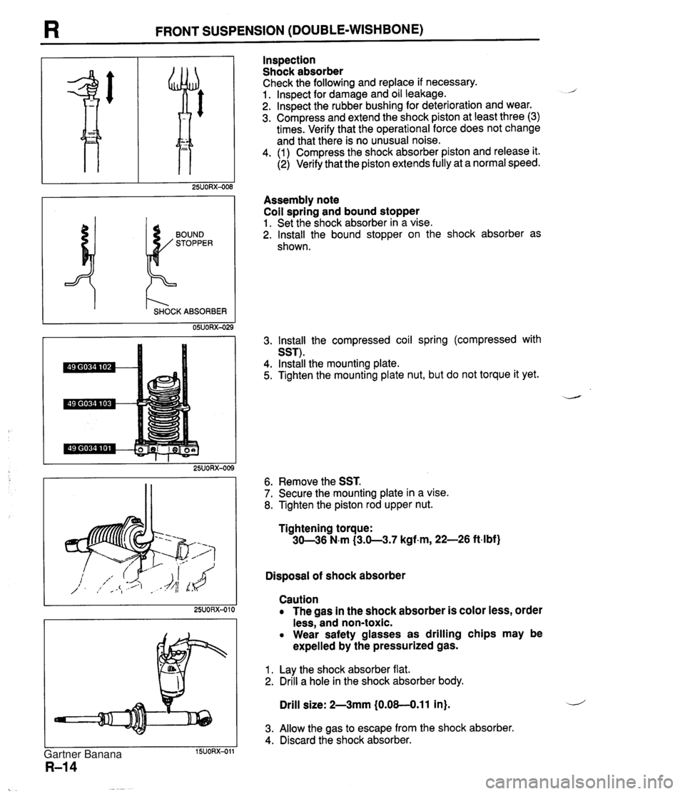
I3 FRONT SUSPENSION (DOUBLE-WISHBONE) I t'- SHOCK ABSORBER 05UORX-02 Inspection Shock absorber Check the following and replace if necessary. 1. lnspect for damage and oil leakage. 2. lnspect the rubber bushing for deterioration and wear. 3. Compress and extend the shock piston at least three (3) times. Verify that the operational force does not change and that there is no unusual noise. 4. (1) Compress the shock absorber piston and release it. (2) Verify that the piston extends fully at a normal speed. Assembly note Coil spring and bound stopper 1. Set the shock absorber in a vise. 2. Install the bound stopper on the shock absorber as shown. 3. lnstall the compressed coil spring (compressed with SST). 4. Install the mounting plate. 5. Tighten the mounting plate nut, but do not torque it yet. 6. Remove the SST. 7. Secure the mounting plate in a vise. 8. Tighten the piston rod upper nut. Tightening torque: 30-36 N.m (3.0-3.7 kgf.m, 22-26 ftdbf) Disposal of shock absorber Caution The gas in the shock absorber is color less, order less, and non-toxic. Wear safety glasses as drilling chips may be expelled by the pressurized gas. 1. Lay the shock absorber flat. 2. Drill a hole in the shock absorber body. Drill size: 2-3mm (0.08-0.11 in). 3. Allow the gas to escape from the shock absorber. 4. Discard the shock absorber. Gartner Banana
Page 753 of 1708

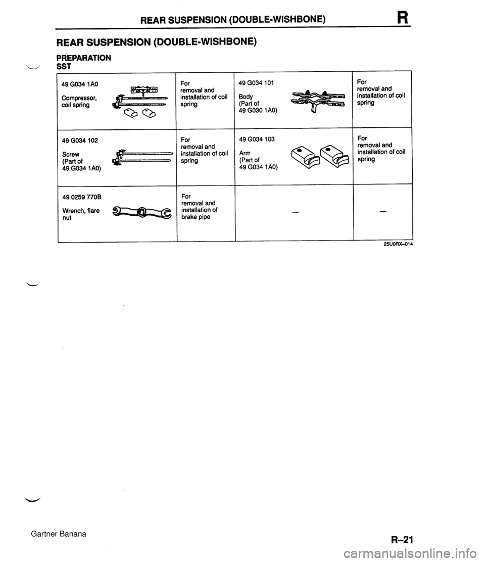
REAR SUSPENSION (DOUBLE-WISHBONE) R REAR SUSPENSION (DOUBLE-WISHBONE) PREPARATION L., SST Compressor, coil spring Screw (Part of 49 GO34 1 AO) 49 0259 7708 Wrench, flare nut For 1 49 GO34 I01 For 1 49 GO34 103 removal and installation of coil spring Body (Part of 49 GO30 I AO) For removal and installation of brake pipe removal and installation of coil spring For removal and installation of coil spring Arm (Part of 49 GO34 1 AO) For removal and installation of coil spring Gartner Banana
Page 846 of 1708

BODY ELECTRICAL SYSTEM ................................... INDEX T- 2 ........................... SWITCHES T- 2 FUSES AND RELAYS .................. T- 3 .............................. LIGHTS T- 4 CRUISE CONTROL SYSTEM ........... T- 5 ...................... AUDIO SYSTEM T- 6 SRS AIR BAG SYSTEM ................ T- 7 ............................... OUTLINE T- 8 TROUBLESHOOTING GUIDE ........... T- 8 ELECTRICAL SYMBOLS ............... T- 9 ................................... FUSE T- 10 STRUCTURAL VIEW ................... T- 10 ...................... SPECIFICATIONS T- 11 ........................ DESCRIPTION T- 12 ....................... REPLACEMENT T- 12 ....................... RELAY .. ....... T- 13 STRUCTURAL VIEW ................... T- 13 ........................ DESCRIPTION T- 13 RETRACTABLE HEADLIGHT RELAY .... T- 14 ....................... FLASHER UNIT T- 14 ........................... TNS RELAY T- 15 .......................... HORN RELAY T- 15 COOLANT FAN RELAY ................. T- 15 REAR WINDOW DEFROSTER RELAY ... T- 16 HEADLIGHT RELAY ................... T- 16 ................................ SWITCH T- 17 ................... STRUCTURAL VIEW T- 17 ........................ DESCRIPTION T- 17 .................... IGNITION SWITCH T- 18 COMBINATION SWITCH ............... T- 19 RETRACTOR SWITCH AND HAZARD WARNING ............................. SWITCH T- 21 ................. INSTRUMENT CLUSTER T- 22 ................... STRUCTURAL VIEW T- 22 ........................ DESCRIPTION T- 22 .................... CIRCUIT DIAGRAM T- 23 ................. TROUBLESHOOTING T- 24 ............ REMOVAL / INSTALLATION T- 29 ........... DISASSEMBLY 1 ASSEMBLY T- 29 ...................... SPEEDOMETER T- 30 ........................ TACHOMETER T- 30 WATER TEMPERATURE GAUGE ....... T- 30 ......................... FUEL GAUGE T- 31 OIL PRESSURE GAUGE ............... T- 31 .................... PRINTED CIRCUIT T- 32 VEHICLE SPEED SENSOR ............. T- 32 WATER TEMPERATURE SENDER UNlT . T- 32 FUEL GAUGE SENDER UNlT ...................... (IN FUEL TANK) T- 32 OIL PRESSURE SENSOR .............. T- 33 ............... SPEEDOMETER CABLE T- 33 WARNING LIGHT AND SENDER UNIT ..... T- 34 ................... STRUCTURAL VIEW T- 34 CIRCUIT DIAGRAM .................... T- 35 ................. TROUBLESHOOTING T- 36 BRAKE FLUID LEVEL SENSOR ......... T- 39 PARKING BRAKE SWITCH ............. T- 39 ..................... BUCKLE SWITCH T- 39 ...................... LIGHTING SYSTEM T- 40 ................... STRUCTURAL VIEW T- 40 ......................... HEADLIGHTS T- 41 ......................... STOPLIGHTS T- 53 TURN AND HAZARD WARNING LIGHTS . T- 57 ..................... BACK-UP LIGHTS T- 66 TAILLIGHTS. SIDE MARKER LIGHTS. PARKING LIGHTS AND LICENSE PLATE LIGHTS . T- 69 DAYTIME RUNNING LIGHTS (DRL) .................... (CANADA SPEC.) T- 72 ........... REAR COMBINATION LIGHT T- 76 .................... INTERIOR LIGHTS T- 78 ................ ILLUMINATION LIGHTS T- 82 .................................. HORN T- 84 ................... STRUCTURAL VIEW T- 84 .................... CIRCUIT DIAGRAM T- 85 ................. TROUBLESHOOTING T- 86 ............ REMOVAL 1 INSTALLATION T- 87 ............ REAR WINDOW DEFROSTER T- 89 ................... STRUCTURAL VIEW T- 89 ........................ DESCRIPTION T- 89 ................. TROUBLESHOOTING T- 90 ................ REPAIRING FILAMENT T- 93 ............. CRUISE CONTROL SYSTEM T- 94 ................... STRUCTURAL VIEW T- 94 .................... CIRCUIT DIAGRAM T- 95 ................. TROUBLESHOOTING T- 96 ....... SELF-DIAGNOSTIC INSPECTION T-100 ............... CRUISE CONTROL UNIT T-103 .................... ACTUATOR CABLE T-104 ..................... CLUTCH SWITCH T-105 .......... STOP LIGHTIBRAKE SWITCH T-105 ...... CRUISE CONTROL MAIN SWITCH T-106 ........... CRUISE CONTROL SWITCH T-106 ............. VEHICLE SPEED SENSOR T-106 ........................... ACTUATOR T-107 a .................................. AUDIO T-108 ................... STRUCTURAL VIEW T-108 ................... SYSTEM DIAGRAM T-109 ............................ FEATURES T-110 FUNCTION AND OPERATING ......................... PROCEDURE 1-111 ............. OPERATION DESCRIPTION T-113 .................. ANTITHEFT SYSTEM T-120 ................. TROUBLESHOOTING T-122 ............ REMOVAL I INSTALLATION T-145 .................... POWER ANTENNA T-149 ......................... INSPECTION T-153 CONNECTOR TERMINAL .................... SPECIFICATIONS T-154 SRS AIR BAG SYSTEM .................. T-156 PREPARATION ........................ T-156 ................... STRUCTURAL VIEW T-156 .......... COMPONENT DESCRIPTION T-157 SYSTEM DIAGRAM ................... T-158 ................. SERVICE WARNINGS T-159 GENERAL PROCEDURES ............. T-160 TROUBLESHOOTING ................. T-160 DRIVER-SIDE AIR BAG MODULE ....... T-206 PASSENGER-SIDE AIR BAG MODULE . . T-207 DIAGNOSTIC MODULE ................ T-208 CLOCK SPRING ....................... T-209 CRASH SENSOR (D-SENSOR) ......... T-210 CRASH SENSOR (S-SENSOR) ......... T-213 AIR BAG MODULE DISPOSAL . .. PROCEDURE ........................ T-215 INSPECTION OF SST (DEPLOYMENT TOOL) ............... T-217 Gartner Banana
Page 853 of 1708

T OUTLINE OUTLINE TROUBLESHOOTING GUIDE Symptom a Speedometer does not operate or indication is incorrect a Tachometer does not operate Water temperature gauge does not operate Fuel gauge does not operate a Oil pressure gauge does not operate a Brake system warning light remains illuminated Brake system warning light does not illuminate when parking brake on a Brake system warning light does not illuminate when brake fluid in reservoir is below MIN a OID off indicator light does not illuminate when OID off switch turned on Seat belt warning light remains on six seconds after ignition switch is turned on (Timer function does not operate) Seat belt warning light does not illuminate when ignition switch is first turned on a Headlights do not illuminate Headlight does not illuminate (Right or left) Retractable headlight actuator do not operate (Both sides) Retractable headlight actuator does not operate (One side) Stoplights do not illuminate (All) Stoplight does not illuminate (One only) Turn and hazard warning functions do not operate Turn signals not operate (Hazard warning function operates normally) Hazard warning function does not operate (Turn signals function normally) Back-up lights does not illuminate Taillights, side marker lights, and license plate lights do not illuminate Daytime running lights do not illuminate Daytime running light function does not cancel lnterior lights do not illuminate Interior liahts remains illuminated (Control switch: DOOR ~osition) Horn does not sound Vehicle speed cannot be set (Cruise control unit will not hold vehicle speed) Speakers do not operate (Without headrest speakers) Speakers do not operate (With headrest speakers) Poor sound quality or noise (Radio) Poor sound quality (Cassette tape player) Cassette tape will not load Cassette tape will not play Compact disc will not load Compact disc skips No sound can be heard Some speakers do not operate Bodysonic will not play Service code table (With passenger-side air bag) Service code table (With out ~assenaer-side air baa) Reference page T-24 T-25 T-26 T-27 T-28 T-36 T-37 T-37 Gartner Banana
Page 854 of 1708

OUTLINE T NO type relay I STOP Not in operation (No power supply) ax FLOW I STOP NC type relay NO switch In operation (Power supply) ELECTRICAL SYMBOLS Switches and Relays There is an NC (normally closed) and NO (normally open) indication for switches and relays that shows when no change of operation conditions has occurred. Relay Switch I w FLOW - Other Electrical Symbols - ax STOP FLOW NC switch FLOW STOP I I I I - FUSIBLE LINK e $1 VARIABLE RESISTOR + LIGHT TRANSISTOR HOLDER BOX FUSE 4 RESISTOR 1 T CONDENSER BATTERY 4) MOTOR 8 THERMISTOR SPEAKER I CIGARETTE LIGHTER I HEATER - - BODY GROUND t COIL, SOLENOID + DIODE I 25UOTX-010 Gartner Banana