oil MAZDA MX-5 1994 Workshop Manual
[x] Cancel search | Manufacturer: MAZDA, Model Year: 1994, Model line: MX-5, Model: MAZDA MX-5 1994Pages: 1708, PDF Size: 82.34 MB
Page 867 of 1708

T INSTRUMENT CLUSTER INSTRUMENT CLUSTER STRUCTURAL VIEW 1. Speedometer 2. Tachometer 3. Water temperature gauge 4. Fuel gauge 5. Oil pressure gauge 6. Warning and indicator lights 7. Trip meter 8. Odometer DESCRIPTION Speedometer Two scales are shown on the speedometer face. The main scale for U.S. specification vehicles is MPH (0-140 MPH); the main scale for Canada specification vehicles is kmlh (0-220 kmlh). The odometer indication is the same as the main scale. Tachometer The tachometer has a RED STRIPED ZONE (6,500-7,000 rpm) that indicates momentary allowable engine speed. The engine should not be operated in the RED ZONE (7,000-8,000 rpm). Fuel Gauge 2 The fuel gauge continues to indicate the amount of fuel remaining in the fuel tank after the ignition switch has been turned OFF. Gartner Banana
Page 873 of 1708
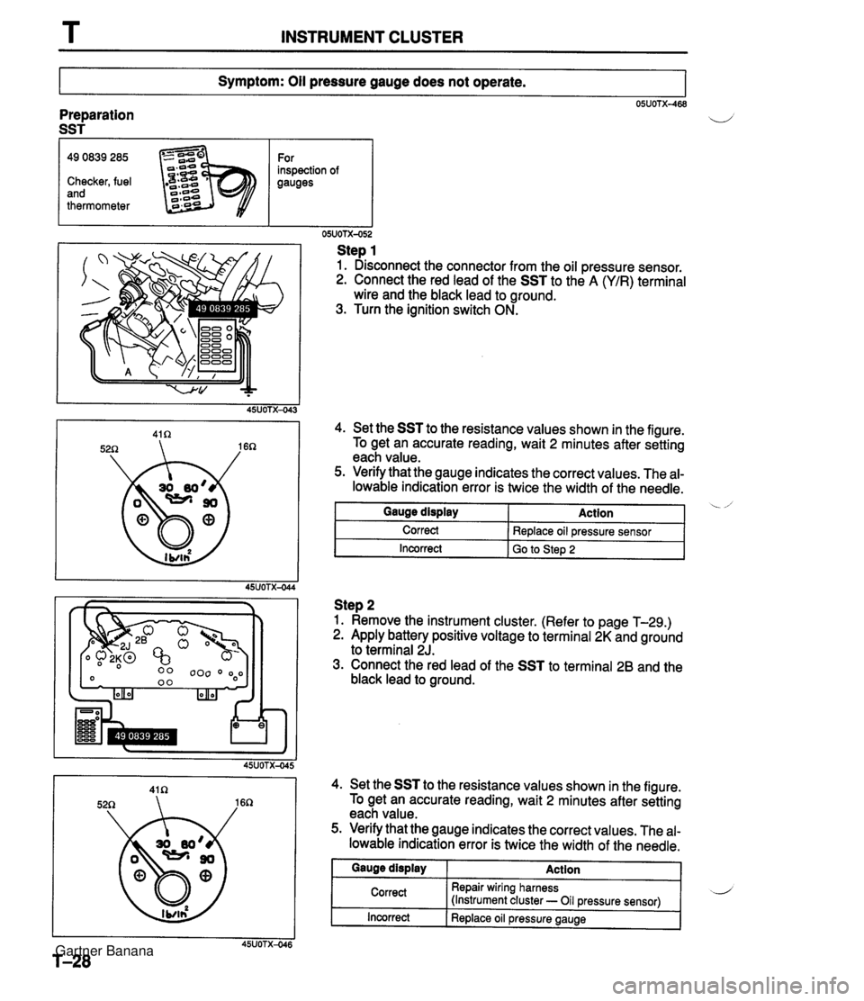
T INSTRUMENT CLUSTER Symptom: Oil pressure gauge does not operate. 05UOTX-468 Preparation SST I 49 0839 285 For inspection of Checker, fuel gauges and thermometer Step 1 1. Disconnect the connector from the oil pressure sensor. 2. Connect the red lead of the SST to the A (YIR) terminal wire and the black lead to ground. 3. Turn the ignition switch ON. 4. Set the SST to the resistance values shown in the figure. To get an accurate reading, wait 2 minutes after setting each value. 5. Verify that the gauge indicates the correct values. The al- lowable indication error is twice the width of the needle. I Incorrect I GO to step 2 Gauge display Correct Step 2 1. Remove the instrument cluster. (Refer to page T-29.) 2. Apply battery positive voltage to terminal 2K and ground to terminal 2J. 3. Connect the red lead of the SST to terminal 26 and the black lead to ground. Action Replace oil pressure sensor 4. Set the SST to the resistance values shown in the figure. To get an accurate reading, wait 2 minutes after setting each value. 5. Verify that the gauge indicates the correct values. The al- lowable indication error is twice the width of the needle. Incorrect I Replace oil pressure gauge Gauge display Correct Action Repair wiring harness (Instrument cluster - Oil pressure sensor) Gartner Banana
Page 876 of 1708
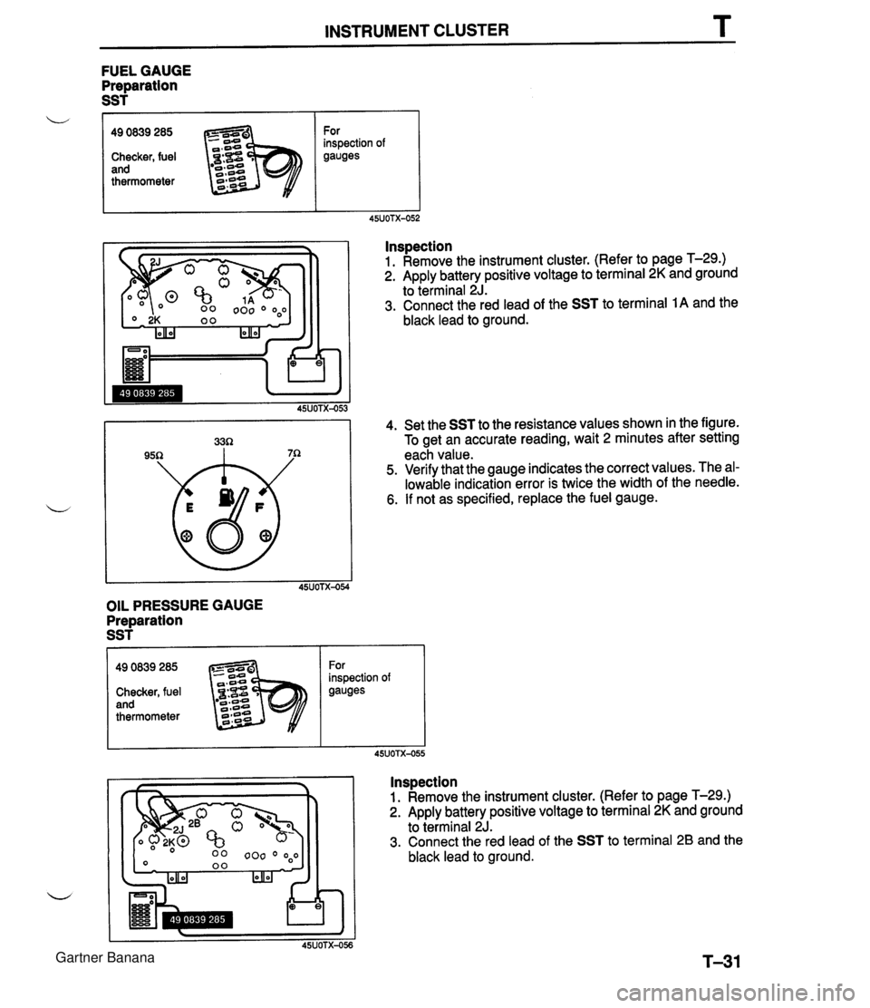
INSTRUMENT CLUSTER T FUEL GAUGE Preparation SST f OIL PRESSURE GAUGE Preparation SST L lnspection 1. Remove the instrument cluster. (Refer to page T-29.) 2. Apply battery positive voltage to terminal 2K and ground to terminal 2J. 3. Connect the red lead of the SST to terminal 1A and the black lead to ground. 4. Set the SST to the resistance values shown in the figure. To get an accurate reading, wait 2 minutes after setting each value. 5. Verify that the gauge indicates the correct values. The al- lowable indication error is twice the width of the needle. 6. If not as specified, replace the fuel gauge. 49 0839 285 Checker, fuel and thermometer For inspection of gauges Inspection 1. Remove the instrument cluster. (Refer to page T-29.) 2. Apply battery positive voltage to terminal 2K and ground to terminal 2J. 3. Connect the red lead of the SST to terminal 2B and the black lead to ground. 49 0839 285 Checker, fuel and thermometer For inspection of gauges Gartner Banana
Page 877 of 1708
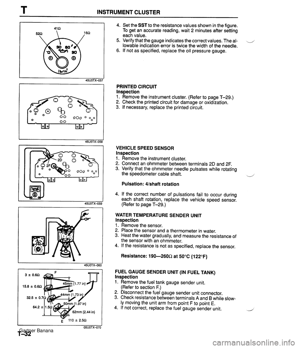
T INSTRUMENT CLUSTER 4. Set the SST to the resistance values shown in the figure. To get an accurate reading, wait 2 minutes after setting each value. 5. Verify that the gauge indicates the correct values. The al- \J lowable indication error is twice the width of the needle. 6. If not as specified, replace the oil pressure gauge. PRINTED CIRCUIT lnspection 1. Remove the instrument cluster. (Refer to page T-29.) 2. Check the printed circuit for damage or oxidization. 3. If necessary, replace the printed circuit. VEHICLE SPEED SENSOR lnspection 1. Remove the instrument cluster. 2. Connect an ohmmeter between terminals 2D and 2F. 3. Verify that the ohmmeter needle pulsates while rotating the speedometer cable shaft. ~ Pulsation: Ushaft rotation 4. If the correct number of pulsations fail to occur during each shaft rotation, replace the vehicle speed sensor. (Refer to page T-29.) WATER TEMPERATURE SENDER UNlT lnspection 1. Remove the sensor. 2. Place the sensor and a thermometer in water. 3. Heat the water gradually, and measure the resistance of the sensor with an ohmmeter. 4. If the resistance is not as specified, replace the sensor. Resistance: 190-260Q at 50°C (1 22°F) FUEL GAUGE SENDER UNlT (IN FUEL TANK) lnspection 1. Remove the fuel tank gauge sender unit. (Refer to section F.) 2. Disconnect the fuel gauge sender unit connector. 3. Check resistance between terminals A and B while slow- ly moving the unit arm from point F to point E. 4. If not correct, replace the fuel gauge sender unit. 2 Gartner Banana
Page 878 of 1708

INSTRUMENT CLUSTER T I OIL PRESSURE SENSOR 3. If not as specified, replace the oil pressure sensor. OIL PRESSURE SENSOR lnspection 1. Disconnect the oil pressure sensor connector. 2. Measure resistance between the oil pressure sensor and a body ground as shown. SPEEDOMETER CABLE lnspection 1. Disconnect the speedometer cable from the instrument cluster and transmission case. 2. Verify that the cable and gear spin easily when turned by hand. 3. If the cable or gear is stiff, replace as necessary. Condition Engine stopped Engine running Resistance 110-13052 13- 55R Gartner Banana
Page 1073 of 1708
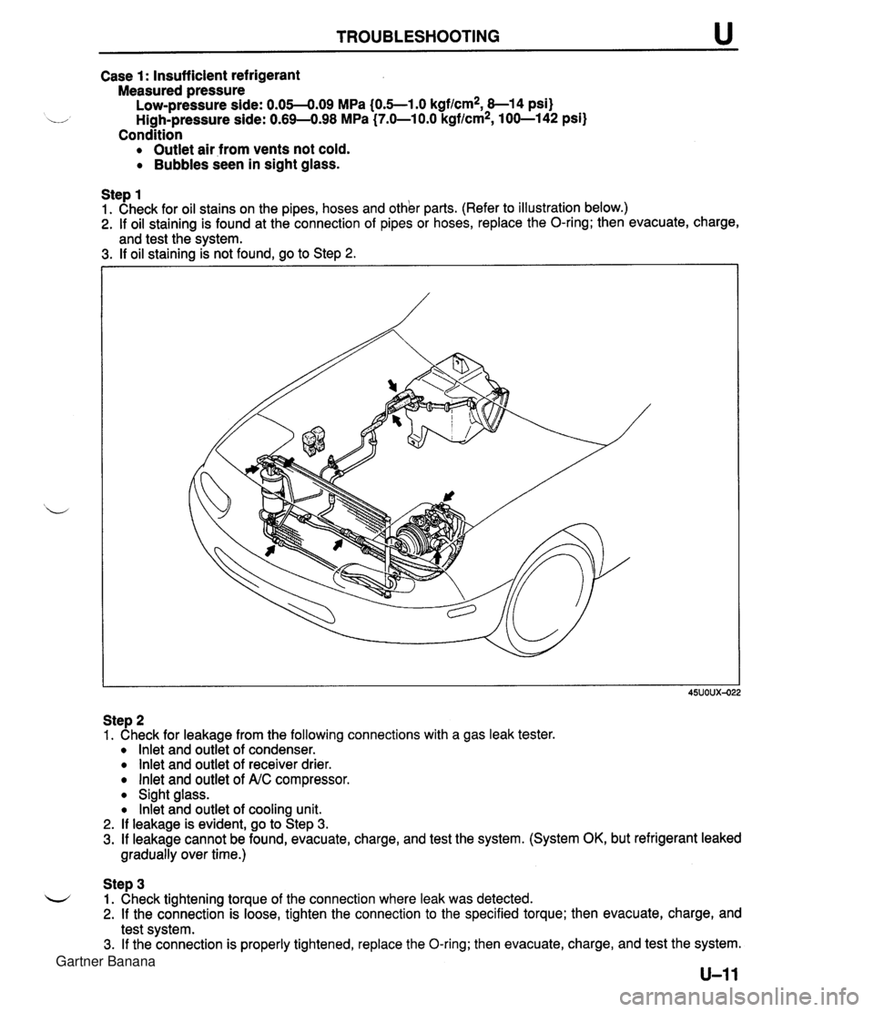
TROUBLESHOOTING Case 1: Insufficient refrigerant Measured pressure Low-pressure side: 0.05-4.09 MPa (0.5--1.0 kgf/cm2, 8-1 4 psi) u High-pressure side: 0.69-498 MPa (7.0-1 0.0 kgflcm2, 100-142 psi) Condition Outlet air from vents not cold. Bubbles seen in sight glass. Step 1 1. Check for oil stains on the pipes, hoses and other parts. (Refer to illustration below.) 2. If oil staining is found at the connection of pipes or hoses, replace the O-ring; then evacuate, charge, and test the svstem. 3. If oil staining k not found, go to Step 2. Step 2 1. Check for leakage from the following connections with a gas leak tester. lnlet and outlet of condenser. lnlet and outlet of receiver drier. lnlet and outlet of A.C compressor. Sight glass. lnkt and outlet of cooling unit. 2. If leakage is evident, go to Step 3. 3. If leakage cannot be found, evacuate, charge, and test the system. (System OK, but refrigerant leaked gradually over time.) Step 3 L-/ 1. Check tightening torque of the connection where leak was detected. 2. If the connection is loose, tighten the connection to the specified torque; then evacuate, charge, and test system. 3. If the connection is properly tightened, replace the O-ring; then evacuate, charge, and test the system. Gartner Banana
Page 1086 of 1708

u AIR CONDITIONER SERVICE WARNINGS Storing Refrigerant The refrigerant container is highly pressurized. If it is subjected to high heat, it could explode, scattering u metal fragments and liquid refrigerant that can seri- ously injure you. Store the refrigerant at tempera- tures below 40°C (1 04°F). Handling Refrigerant Handling liquid refrigerant is dangerous. A drop of it on the skin can result in localized frostabite. When handling the refrigerant, wear gloves and safety goggles. If refrigerant splashes into the eyes, im- mediately wash them with clean water and consult a doctor. SERVICE CAUTIONS Compressor oil (ND-OILS) Do not spill compressor oil on the vehicle. A drop of compressor oil on the vehicle surface can eat away at the paint. If oil gets on the vehicle, wipe it off im- mediately. b PAG compressor oil (ND-OILS) has a higher mois- ture absorption efficiency than the previously used mineral oil. If moisture mixes with the compressor oil, the refrigerant system could be damaged. There- fore, install caps immediately after using the com- pressor oil or removing refrigerant system parts to prevent moisture absorption. Gartner Banana
Page 1092 of 1708
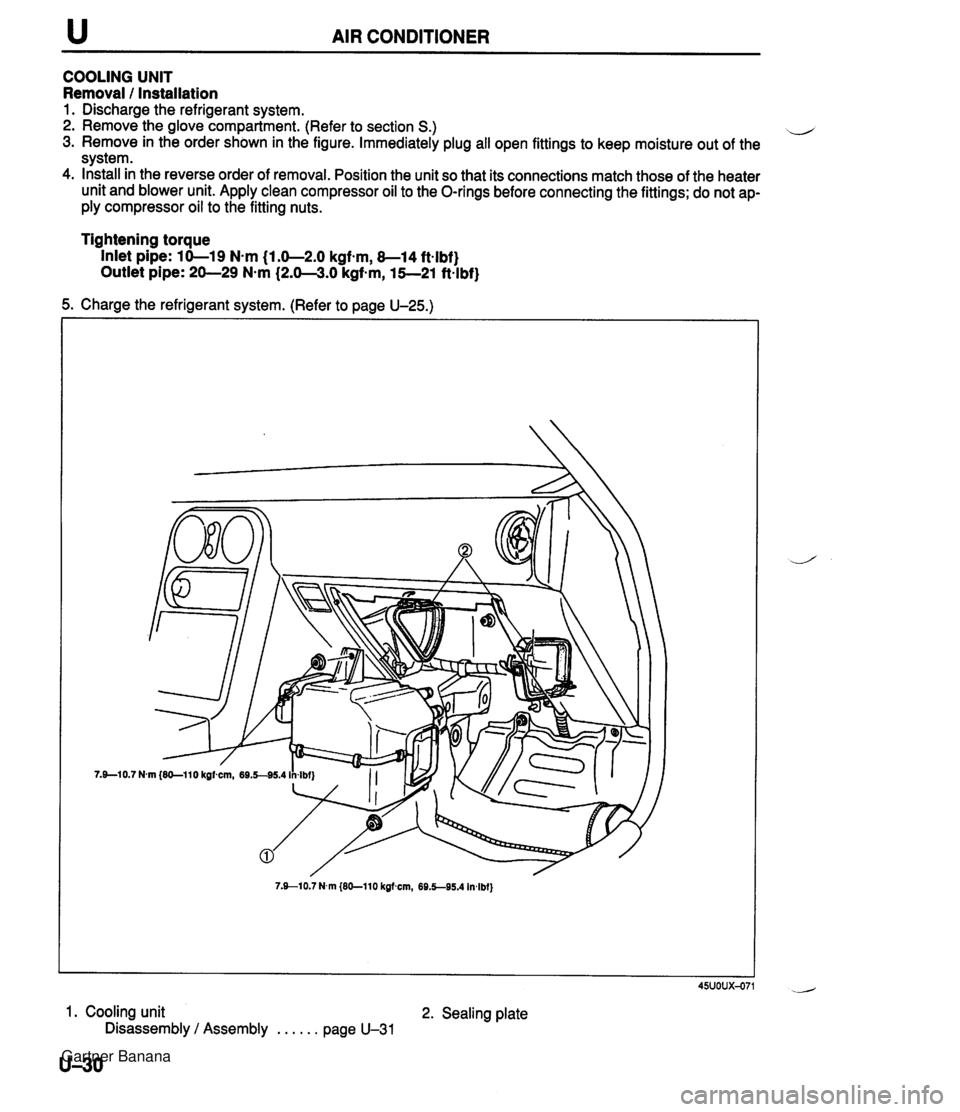
u AIR CONDITIONER COOLING UNIT Removal 1 Installation 1. Discharge the refrigerant system. 2. Remove the glove compartment. (Refer to section S.) il 3. Remove in the order shown in the figure. Immediately plug all open fittings to keep moisture out of the system. 4. Install in the reverse order of removal. Position the unit so that its connections match those of the heater unit and blower unit. Apply clean compressor oil to the O-rings before connecting the fittings; do not ap- ply compressor oil to the fitting nuts. Tightening torque Inlet pipe: 10-19 N-m (1.0-2.0 kgfsm, 8-14 ft-lbf} Outlet pipe: 20-29 N-m (2.0-3.0 kgf-m, 15--21 ft-lbf} 5. Charge the refrigerant system. (Refer to page U-25.) 7.910.7 N.m {EO-110 kgfmn, 69.5-95.4 In4bf} 45uoux-071 1. Cooling unit 2. Sealing plate Disassembly / Assembly . . . . . . page U-31 U-30 Gartner Banana
Page 1093 of 1708
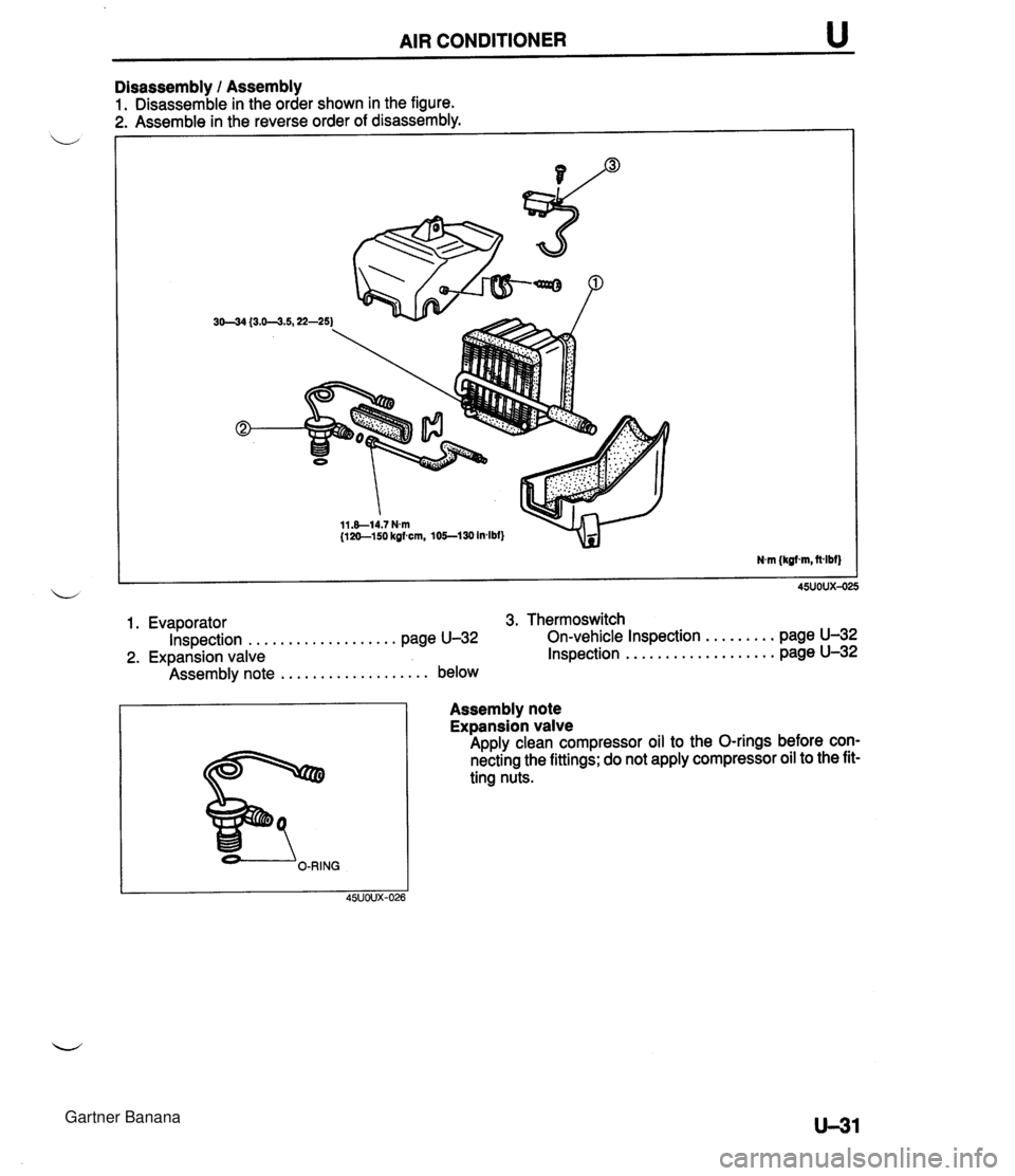
AIR CONDITIONER u Disassembly 1 Assembly 1. Disassemble in the order shown in the figure. 1. Evaporator 3. Thermoswitch ................... ......... Inspection page U-32 On-vehicle Inspection page U-32 ................... 2. Expansion valve Inspection page U-32 ................... Assembly note below Assembly note Expansion valve Apply clean compressor oil to the O-rings before con- necting the fittings; do not apply compressor oil to the fit- ting nuts. Gartner Banana
Page 1094 of 1708
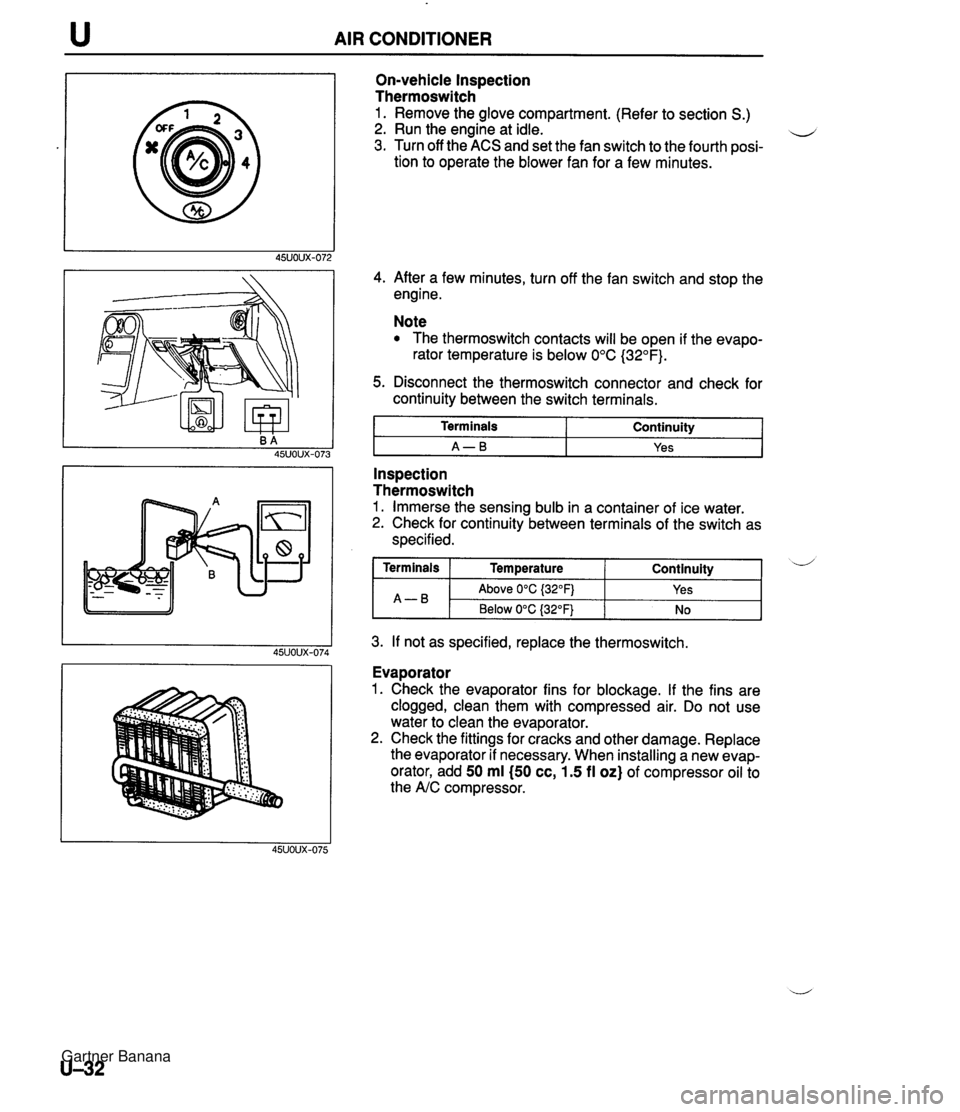
AIR CONDITIONER On-vehicle Inspection Thermoswitch 1. Remove the glove compartment. (Refer to section S.) 2. Run the engine at idle. u 3. Turn off the ACS and set the fan switch to the fourth posi- tion to operate the blower fan for a few minutes. 4. After a few minutes, turn off the fan switch and stop the engine. Note The thermoswitch contacts will be open if the evapo- rator temperature is below 0°C (32°F). 5. Disconnect the thermoswitch connector and check for continuity between the switch terminals. I Terminals I Continuity I I A-B I Yes I - -- Inspection Thermoswitch 1. Immerse the sensing bulb in a container of ice water. 2. Check for continuity between terminals of the switch as specified. 3. If not as specified, replace the thermoswitch. Continuity ( Terminals I Temperature A-B Evaporator 1. Check the evaporator fins for blockage. If the fins are clogged, clean them with compressed air. Do not use water to clean the evaporator. 2. Check the fittings for cracks and other damage. Replace the evaporator if necessary. When installing a new evap- orator, add 50 ml (50 cc, 1.5 fl oz) of compressor oil to the A/C compressor. d Above 0°C {32OFj Below 0°C (32°F) Yes No Gartner Banana