SECTION T MAZDA MX-5 1994 Owner's Manual
[x] Cancel search | Manufacturer: MAZDA, Model Year: 1994, Model line: MX-5, Model: MAZDA MX-5 1994Pages: 1708, PDF Size: 82.34 MB
Page 105 of 1708
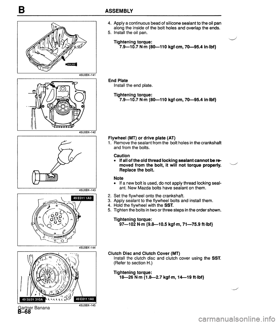
B ASSEMBLY 4. Apply a continuous bead of silicone sealant to the oil pan along the inside of the bolt holes and overlap the ends. 5. Install the oil pan. ij Tightening torque: 7.9-10.7 N.m (80-110 kgf-cm, 70-95.4 in4bf) End Plate Install the end plate. Tightening torque: 7.9--10.7 N.m (80-110 kgf.cm, 70-95.4 in-lbf) Flywheel (MT) or drive plate (AT) 1. Remove the sealant from the bolt holes in the crankshaft and from the bolts. Caution If all of the old thread locking sealant cannot be re- moved from the bolt, it will not torque properly. - Replace the bolt. Note If a new bolt is used, do not apply thread locking seal- ant. New Mazda bolts have sealant on them. 2. Set the flywheel onto the crankshaft. 3. Apply sealant to the flywheel bolts and install them. 4. Hold the flywheel with the SST. 5. Tighten the bolts in two or three steps in the order shown. Tightening torque: 97-102 N.m (9.8-10.5 kgf+m, 71-75.9 ft.lbf) Clutch Disc and Clutch Cover (MT) Install the clutch disc and clutch cover using the SST. (Refer to section H.) Tightening torque: 18-26 N.m (1.8-2.7 kgf.m, 14--19 ftlbf) Gartner Banana
Page 114 of 1708

ASSEMBLY B AUXILIARY PARTS Torque Specifications I FRONT OIL COOLER INSTALLATION REFER TO SECTION D Engine Hanger Install the front and rear engine hangers. Tightening torque: 38-51 N.m (3.8-5.3 kgf.m, 28-38 ft4bf) Gartner Banana
Page 123 of 1708
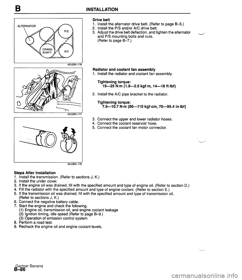
B INSTALLATION ALTERNATOR Drive belt 1. lnstall the alternator drive belt. (Refer to page B-5.) 2. lnstall the PIS and/or AIC drive belt. 3. Adjust the drive belt deflection, and tighten the alternator - and PIS mounting bolts and nuts. (Refer to page 8-7.) Radiator and coolant fan assembly 1. lnstall the radiator and coolant fan assembly. Tightening torque: 19-25 N.m (1.9-2.6 kgf.m, 14--18 ft4bf) 2. lnstall the AIC pipe bracket to the radiator Tightening torque: 7.9-10.7 N.m (80-110 kgf.cm, 70-95.4 in4bf) 3. Connect the upper and lower radiator hoses. 4. Connect the coolant reservoir hose. 5. Connect the coolant fan motor connector. Steps After Installation 1. lhstall the transmission. (Refer to sections J, K.) 2. lnstall the under cover. 3. If the engine oil was drained, fill with the specified amount and type of engine oil. (Refer to section D.) 4. Fill the radiator with the specified amount and type of engine coolant. (Refer to section E.) 5. If the transmission oil was drained, fill with the specified amount and type of transmission oil. (Refer to sections J, K.) 6. Connect the negative battery cable. 7. Start the engine and check the following. (1) Engine oil, transmission oil, and engine coolant leakage (2) Ignition timing, idle speed (Refer to page 59.) (3) Operation of emission control system 8. Perform a road test. 9. Recheck the engine oil and engine coolant levels. Gartner Banana
Page 124 of 1708

Before beginning any service procedure. refer to section T of this manual for air bag system service warnings and audio antitheft system alarm conditions . LUBRICATION SYSTEM INDEX ....................................... D- 2 ..................................... OUTLINE D- 3 ........................... SPECIFICATIONS D- 3 TROUBLESHOOTING GUIDE .................. D- 3 OIL PRESSURE .............................. D- 4 PREPARATION ............................. D- 4 INSPECTION ............................... D- 4 ENGINE OIL .................................. D- 5 INSPECTION ............................... D- 5 REPLACEMENT ............................ D- 5 OIL FILTER ................................... D- 6 REPLACEMENT ............................ D- 6 OIL COOLER ................................. D- 7 REMOVAL / INSTALLATION .................. D- 7 OIL PAN ..................................... D- 8 REMOVAL / INSTALLATION .................. D- 8 OIL PUMP .................................... D-11 DISASSEMBLY / ASSEMBLY ................. D-11 INSPECTION ............................... D-12 45UODX401 Gartner Banana
Page 125 of 1708

INDEX INDEX HYDRAULIC LASH ADJUSTER (HLA) REMOVAL / INSPECTION I INSTALLATION, SECTION B ENGINE OIL SPECIFICATION API SERVICE SG, SH (ECII) ILSAC TOTAL CAPACITY 4.0 L (4.2 US qt, 3.5 Imp qt) 1. Oil pressure 4. Oil cooler Inspection ................. page D- 4 Removal I Installation ....... page D- 7 2. Engine oil 5. Oil pan Inspection ................. page D- 5 Removal / Installation ....... page D- 8 Replacement .............. page D- 5 6. Oil pump _-' 3. Oil filter Disassembly I Assembly .... page D-11 .............. Replacement page D- 6 Inspection ................. page D-12 Gartner Banana
Page 126 of 1708
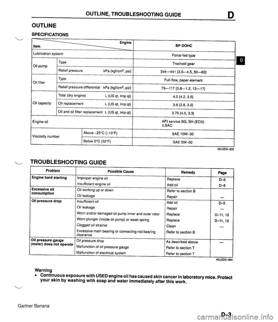
OUTLINE, TROUBLESHOOTING GUIDE D OUTLINE SPECIFICATIONS Engine BP DOHC Lubrication system Oil capacity Engine oil Force-fed type Trochoid gear 344--441 {3.5-4.5,50--63) Full-flow, paper element 79--117 {0.&1.2, 12-1 7) Oil pump Oil filter Oil and oil filter replacement L {US qt, Imp qt) API service SG, SH (ECII) l LSAC TY pe Relief pressure kPa {kgf/cm2, psi) Type Relief pressure differential kPa {kgf/cm2, psi) Total (dry engine) L (US qt, Imp qt} Oil replacement L {US qt, Imp qt} 3.75 (4.0, 3.3) 4.0 f4.2, 3.5) 3.6 (3.8,3.2) I TROUBLESHOOTING GUIDE Problem SAE 1 OW-30 SAE 5W-30 Viscosity number Engine hard starting 45UODX-003 Above -25°C (-1 3°F) Below 0°C {32"F} Excessive oil consumption Oil pressure drop Oil pressure gauge (meter) does not operate Warning Possible Cause Improper engine oil Insufficient engine oil Oil working up or down Oil leakage Insufficient oil Oil leakage Worn and/or damaged oil pump inner and outer rotor Worn plunger (inside oil pump) or weak spring Clogged oil strainer Excessive main bearing or connecting rod bearing clearance Oil pressure drop Malfunction of oil pressure gauge Malfunction of electrical system Remedy Replace Add oil Refer to section 6 Repair Add oil Repair Replace Replace Clean Refer to section B As described above Refer to section T Refer to section T Page D-5 D-5 - 0-5 - D-11,12 D-ll,12 - - 45UODX-004 Conthuous exposure with USED engine oil has caused skin cancer in laboratory mice. Protect your skin by washing with soap and water immediately after this work. Gartner Banana
Page 130 of 1708
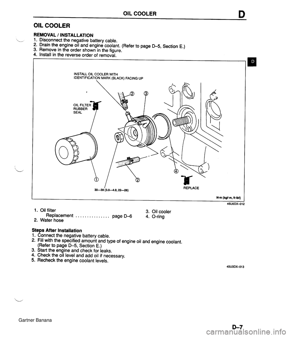
OIL COOLER D OIL COOLER REMOVAL I INSTALLATION 1. Disconnect the negative battery cable. 2. Drain the engine oil and engine coolant. (Refer to page D-5, Section E.) 3. Remove in the order shown in the figure. 4. Install in the reverse order of removal. INSTALL OIL COOLER WITH IDENTIFICATION MARK (BLACK) FACING UP A OIL FILTER^ RUBBER I 3049 (3.0--4.0,22-28) REPLACE Nm {kgtm, ft4bf) 1. Oil filter 3. Oil cooler Replacement . . . . . . . . . . . . . . . Page D-6 4. O-ring 2. Water hose Steps After Installation 1. Connect the negative battery cable. 2. Fill with the specified amount and type of engine oil and engine coolant. (Refer to page D-5, Section E.) 3. Start the engine and check for leaks. 4. Check the oil level and add oil if necessary. 5. Recheck the engine coolant levels. Gartner Banana
Page 131 of 1708

D OIL PAN OIL PAN REMOVAL / INSTALLATION 1. Disconnect the negative battery cable. 2. Drain the engine oil. (Refer to page D-5.) 3. Remove the undercover. 4. Remove in the order shown in the figure, referring to Removal Note. 5. Install in the reverse order of removal, referring to Installation Note. 94--117 (9.5-11.9,69-86) 57-78 (5.8--8.0,42-57) 69-83 {7.0-8.5,51-61) GASKET, REPLAC 7.9--10.7 Nm {60-110 kgfan, 70-95 O-RING, REPLACE 'If 64-49 (6.!%9.1,4&65) 7.9-10.7 N.m (80-110 kgf.crn, 70-95 indbf] 1. Dipstick and pipe 5. Oil pan ............. 2. Intermediate shaft Removal Note page D- 9 ........... .......... Removal / lnstllation section N Installation Note page D-10 3. Engine mount nut 6. Oil strainer 7. Oil baffle ,' ............. Removal Note page D- 9 ............. 4. Crossmember installation bolt and nut Removal Note page D- 9 ............. ........... Removal Note page D- 9 Installation Note page D- 9 Gartner Banana
Page 137 of 1708
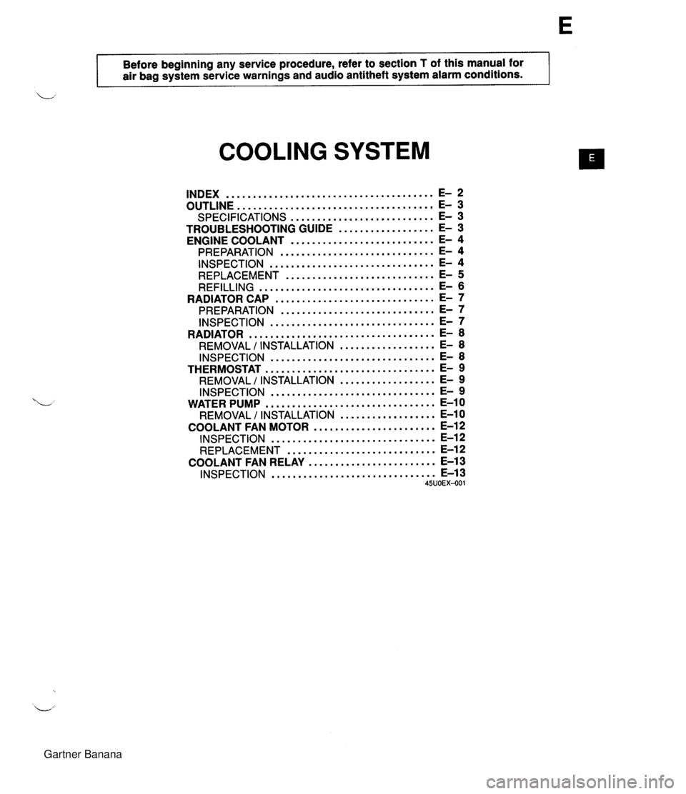
- . - . Before beginning any service procedure, refer to section T of this manual for air bag system service warnings and audio antitheft system alarm conditions . COOLING SYSTEM INDEX ....................................... E- 2 OUTLINE ..................................... E- 3 SPECIFICATIONS ........................... E- 3 TROUBLESHOOTING GUIDE .................. E- 3 ENGINE COOLANT ........................... E- 4 PREPARATION ............................. E- 4 INSPECTION ............................... E- 4 REPLACEMENT ............................ E- 5 REFILLING ................................. E- 6 .............................. RADIATOR CAP E- 7 ............................. PREPARATION E- 7 INSPECTION ............................... E- 7 RADIATOR ................................... E- 8 REMOVAL I INSTALLATION .................. E- 8 INSPECTION ............................... E- 8 THERMOSTAT ................................ E- 9 REMOVAL I INSTALLATION .................. E- 9 INSPECTION ............................... E- 9 WATER PUMP ................................ E-10 REMOVAL / INSTALLATION .................. E-10 COOLANT FAN MOTOR ....................... E-12 INSPECTION ............................... E-12 REPLACEMENT ............................ E-12 ........................ COOLANT FAN RELAY E-13 ............................... INSPECTION E-13 45UOEX-001 Gartner Banana
Page 146 of 1708

WATER PUMP WATER PUMP REMOVAL I INSTALLATION 1. Disconnect the negative battery cable. 2. Drain the engine coolant. (Refer to page E-5 for WARNING and procedure) 3. Remove in the order shown in the figure, referring to Removal Note. 4. Install in the reverse order of removal. 1. Timing belt 4. Water pump Service . . . . . . . . . . . . . . . . . . . . . Section B Inspect for cracks, damaged mounting sur- 2. PIS oil pump face, bearing condition, and leakage. Removal Note . . . . . . . . . . . . . . page E-1 1 If the water pump is damage, replace it. 3. Water hose Do not repair it. 5. Water inlet pipe Gartner Banana