cooling MAZDA MX-5 1994 Owner's Manual
[x] Cancel search | Manufacturer: MAZDA, Model Year: 1994, Model line: MX-5, Model: MAZDA MX-5 1994Pages: 1708, PDF Size: 82.34 MB
Page 1074 of 1708

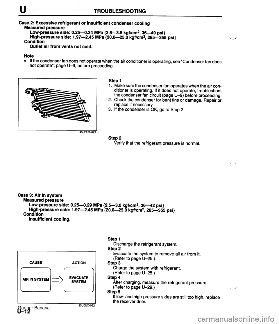
TROUBLESHOOTING Case 2: Excessive refrigerant or insufficient condenser cooling Measured pressure Low-pressure side: 0.254.34 MPa (2.5--3.5 kgf/cm2, 3-9 psi) High-pressure side: 1.97-2.45 MPa (20.0-25.0 kgflcm*, 285--355 psi) Condition Outlet air from vents not cold. Note If the condenser fan does not operate when the air conditioner is operating, see "Condenser fan does not operate"; page U-9, before proceeding. Step 1 1. Make sure the condenser fan operates when the air con- ditioner is operating. If it does not operate, troubleshoot the condenser fan circuit (page U-9) before proceeding. 2. Check the condenser for bent fins or damage. Repair or replace if necessary. 3. If the condenser is OK, go to Step 2. Step 2 Verify that the refrigerant pressure is normal. Case 3: Air in system Measured pressure Low-pressure side: 0.254.29 MPa (2.5--3.0 kgflcmz, 36-42 psi) High-pressure side: 1.97-2.45 MPa (20.0-25.0 kgf/cm2, 285--355 psi) Condition Insufficient cooling. CAUSE ACTION 7 EVACUATE SYSTEM Step 1 Discharge the refrigerant system. Step 2 Evacuate the system to remove all air from it. (Refer to page U-25.) Step 3 Charge the system with refrigerant. (Refer to page U-25.) Step 4 After charging, measure the refrigerant pressure. (Refer to page U-29.) .- Step 5 If low- and high-pressure sides are still too high, replace the receiver drier. Gartner Banana
Page 1075 of 1708

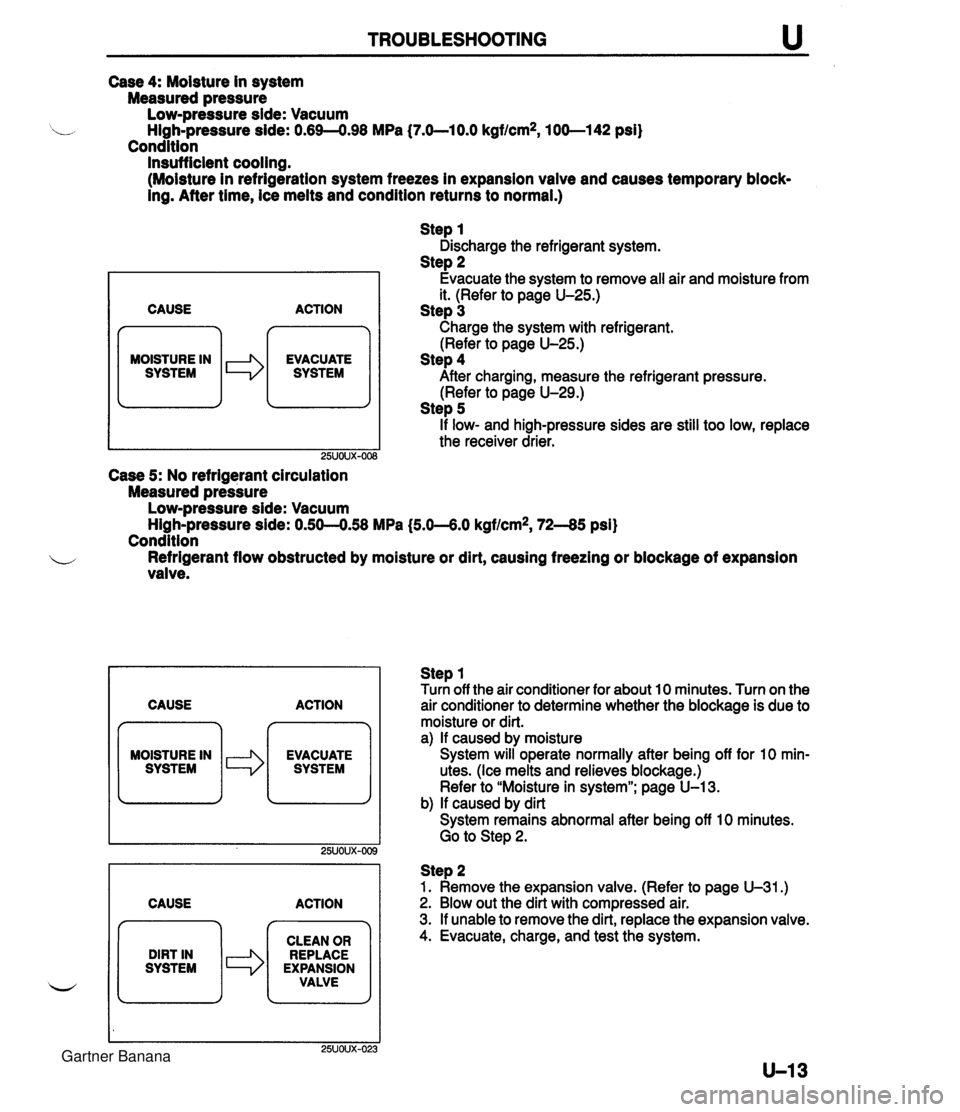
TROUBLESHOOTING Case 4: Moisture in system Measured pressure Low-pressure side: Vacuum High-pressure side: 0.69-4.98 MPa (7.O-lO.O kgf/cm2, 100-1 42 psi) Condition Insufficient cooling. (Moisture in refrigeration system freezes in expansion vaive and causes temporary block- ing. After time, ice melts and condition returns to normal.) CAUSE n MOISTURE IN I SYSTEM le ACTION EVACUATE SYSTEM Step 1 Discharge the refrigerant system. Step 2 Evacuate the system to remove all air and moisture from it. (Refer to page U-25.) Step 3 Charge the system with refrigerant. (Refer to page U-25.) Step 4 After charging, measure the refrigerant pressure. (Refer to page U-29.) Step 5 if low- and high-pressure sides are still too low, replace the receiver drier. Case 5: No refrigerant circulation Measured pressure Low-pressure side: Vacuum ~ighLpressure side: 0.50--0.58 MPa (5.0--6.0 kgf/cm2, 72-45 psi) Condition b Refrigerant flow obstructed by moisture or dirt, causing freezing or blockage of expansion valve. CAUSE ACTION MOISTURE IN CAUSE ACTION Step 1 Turn off the air conditioner for about 10 minutes. Turn on the air conditioner to determine whether the biockage is due to moisture or dirt. a) If caused by moisture System will operate normally after being off for 10 min- utes. (Ice melts and relieves blockage.) Refer to "Moisture in system"; page U-13. b) If caused by dirt System remains abnormal after being off 10 minutes. Go to Step 2. DIRT IN SYSTEM Step 2 1. Remove the expansion valve. (Refer to page U-31.) 2. Blow out the dirt with compressed air. 3. If unable to remove the dirt, replace the expansion valve. 4. Evacuate, charge, and test the system. CLEAN OR REPLACE EXPANSION VALVE Gartner Banana
Page 1076 of 1708

u TROUBLESHOOTING Case 6: Expansion valve stuck open Measured pressure Low-pressure side: 0.30-0.39 MPa {3.0-4.0 kgf/cm2, 43-56 psi) High-pressure side: 1.97-2.45 MPa (20.0-25.0 kgf/cm2, 285-355 psi) Condition Insufficient cooling. CAUSE ACTION 7 m EXPANSION REPLACE / VALWEiUCK I *I EXPANSION VALVE Case 7: Faulty AIC compressor Measured pressure 1. Check whether there is frost or heavy dew on the suction pipe (between cooling unit and AIC compressor). 2. If neither is found, refer to "Excessive refrigerant or insuf- ficient condenser cooling"; page U-12. 3. If either is found, replace the expansion valve. (Refer to page U-31.) LOW-pressure side: 0.4-0.5 MPa (4.0-6.0 kgf/cm2, 57-85 psi) High-pressure side: 0.69-0.98 MPa (7.0-10.0 kgflcm2, 100-1 42 psi) Condition No cooling. I 1 Remedy CAUSE ACTION MOISTURE IN 1. Run ihe engine at a first idle. 2. Verify that the magnetic clutch is on when the ACS and fan switch are on. 3. If the magnetic clutch remains off, refer to "Magnetic clutch does not operate"; page U-7. Gartner Banana
Page 1077 of 1708

HEATER u HEATER STRUCTURAL VIEW 1. Heater unit 45UOUX401 3. Heater control unit Removal 1 Installation ......... page U-16 Removal I lnstallation ......... page U-20 Disassembly / Assembly ...... page U-17 Disassembly l Assembly ...... page U-21 Inspection ................... page U-17 Inspection ................... page U-22 2. Blower unit Adjustment .................. page U-22 Removal 1 Installation ......... page U-18 4. Cooling unit Disassembly I Assembly ...... page U-19 Removal I Installation ......... page U-30 Inspection ................... page U-19 Disassembly / Assembly ...... page U-31 w Note Even in vehicles not equipped with NC, there is a cooling unit. If it is necessary to remove this unit to service the heater, then be sure to reinstall the cooling unit into its original position after servicing is complete. Gartner Banana
Page 1085 of 1708

AIR CONDITIONER U AIR CONDITIONER PREPARATION i, SST I I c STRUCTURAL VIEW 00007-10331 Stopper, magnetic clutch 4992-02-020 Pressure plate remover For removal and installation of magnetic clutch For removal of pressure plate 1. Cooling unit 5. Condenser fan relay Removal I Installation ......... page U-30 Inspection ................... page U-37 Disassembly I Assembly ...... page U-31 6. AX: compressor 2. Condenser Removal I Installation ......... page U-38 Removal I Installation ......... page U-33 Disassembly I Assembly ...... page U-41 w 3. Receiver drier 7. Magnetic clutch Removal / Installation ......... page U-33 Disassembly / Assembly ...... page U-39 4. A/C relay Inspection ................... page U-37 Gartner Banana
Page 1090 of 1708

u AIR CONDITIONER Performance Test After finishing repairs, conduct a performance test of the air conditioning system as follows. 1. Connect the manifold gauge set. (Refer to page U-25.) 2. Start the engine and keep the engine speed at 1,500 rpm. 3. Operate the air conditioner at maximum cooling. 4. Open all windows and doors. 5. Place a dry-bulb thermometer in the center ventilator outlet. 6. Place a dry and wet thermometer close to the blower in- let. 7. Wait until the air conditioner outlet temperature stabi- lizes. If the high-pressure side becomes too high, pour cool water on the condenser. If it is too low, cover the front of the condenser. Stabilized condition Blower inlet temperature: 30-35°C (86-95°F) High-pressure side: 1.38-1.56 MPa (1 4.0-1 6.0 kgflcm*, 200-227 psi) 8. After the air conditioner stabilizes, read the dry and wet thermometer at the air inlet. 9. Calculate the relative humidity from the chart below by comparing the wet- and dry-bulb readings. Gartner Banana
Page 1091 of 1708

AIR CONDITIONER u "C "F 26 24 22 20 18 16 14 12 10 40 59 60 70 RELATIVE HUMIDITY I ltem I Symptom 10. Read the dry thermometer at the air outlet, and calculate the difference between the inlet dry bulb and outlet dry bulb temperatures. 11. Verify that the intersection of the relative humidity and temperature difference is in the shaded zone. Checking Refrigerant Charge 1. Run the engine at a fast idle. 2. Operate the air conditioner at maximum cooling for a few minutes. 3. Determine the amount of refrigerant as shown below by observing the sight glass. 1 Bubbles present in sight glass 2 No bubbles present in sight glass Immediately after air conditioner turned OFF, refrigerant in sight glass stavs clear 141 When air conditioner turned OFF, re- frigerant foams, and then sight glass becomes clear -- Amount of refrigerant Insufficient refrigerant Action Check refrigerant pressure -- Too much or proper amount of refrig- erant Too much refrigerant Checking Refrigerant Pressure 1. Connect the manifold gauge set. (Refer to page U-25.) 2. Operate the engine at 1,500 rpm and set the air condi- tioner to maximum cooling. 3. Measure the low- and high-pressure sides. Turn air conditioner OFF, and watch bubbles (Refer to Items 3 and 4) Check refrigerant pressure Proper amount of refrigerant Stabilized condition Low-pressure side: 0.15-4.24 MPa {I .5--2.5 kgf/cm2, 22-35 psi) High-pressure side: 1.38-1.56 MPa (1 4.61 6.0 kgflcm*, 200-227 psi) Refrigerant amount normal Gartner Banana
Page 1092 of 1708

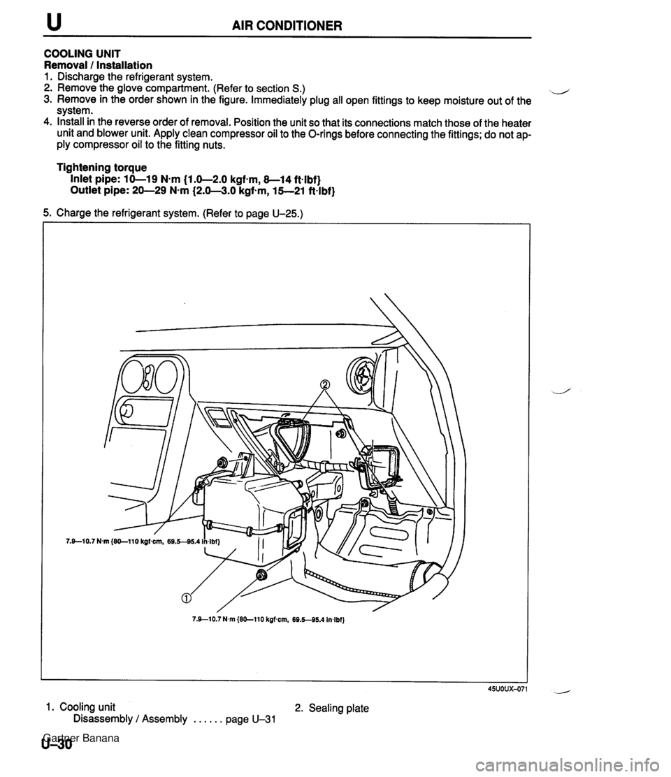
u AIR CONDITIONER COOLING UNIT Removal 1 Installation 1. Discharge the refrigerant system. 2. Remove the glove compartment. (Refer to section S.) il 3. Remove in the order shown in the figure. Immediately plug all open fittings to keep moisture out of the system. 4. Install in the reverse order of removal. Position the unit so that its connections match those of the heater unit and blower unit. Apply clean compressor oil to the O-rings before connecting the fittings; do not ap- ply compressor oil to the fitting nuts. Tightening torque Inlet pipe: 10-19 N-m (1.0-2.0 kgfsm, 8-14 ft-lbf} Outlet pipe: 20-29 N-m (2.0-3.0 kgf-m, 15--21 ft-lbf} 5. Charge the refrigerant system. (Refer to page U-25.) 7.910.7 N.m {EO-110 kgfmn, 69.5-95.4 In4bf} 45uoux-071 1. Cooling unit 2. Sealing plate Disassembly / Assembly . . . . . . page U-31 U-30 Gartner Banana
Page 1098 of 1708

u AIR CONDITIONER CONDENSER FAN Removal / Installation 1. Disconnect the negative battery cable. 2. Disconnect the cooling fan and condenser fan connector. 3. Remove the bolts. 4. Remove in the order shown in the figure. 5. Install in the reverse order of removal. 1. Cooling fan 2. Condenser fan Inspection 1. Disconnect the condenser fan connector. 2. Verify that the condenser fan motor runs when connect- ing battery positive voltage to terminal A and grounding terminal B. B+: Battery positive voltage u 45UOUX-082 U-36 Motor operation Yes Connection B+ A GND B Gartner Banana
Page 1109 of 1708

TECHNICAL DATA MEASUREMENTS ......................... TD- 2 ................................... ENGINE TD- 2 .................... LUBRICATION SYSTEM TD- 5 ........................ COOLING SYSTEM TD- 5 FUEL AND EMISSION CONTROL SYSTEMS . TD- 6 ENGINE ELECTRICAL SYSTEM ............. TD- 7 .................................. CLUTCH TD- 7 .................. MANUAL TRANSMISSION TD- 8 AUTOMATIC TRANSMISSION ............... TD- 9 ....................... PROPELLER SHAFT TD-11 FRONT AND REAR AXLES ................. TD-12 STEERING SYSTEM ....................... TD-12 BRAKING SYSTEM ........................ TD-13 WHEELS AND TIRES ...................... TD-13 ............................. SUSPENSION TD-14 BODY ELECTRICAL SYSTEM ............... TD-15 HEATER AND AIR CONDITIONING SYSTEM . TD-15 STANDARD BOLT AND NUT TIGHTENING ................................. TORQUE TD-15 45UTDX-001 Gartner Banana