cooling MAZDA MX-5 1994 User Guide
[x] Cancel search | Manufacturer: MAZDA, Model Year: 1994, Model line: MX-5, Model: MAZDA MX-5 1994Pages: 1708, PDF Size: 82.34 MB
Page 143 of 1708

RADIATOR CAP RADIATOR CAP INSPECTION Radiator Cap Valve 1. Remove foreign material (such as water residue) from between the radiator cap valve and the valve seat. 2. Attach the radiator cap to a radiator cap tester (commer- cially available) with the SST. Apply pressure gradually to 73.6-1 02 kPa (0.75-1 .O5 kgf/cm2, 10.7-1 4.9 psi). 3. Wait about 10 seconds. Verify that the pressure has not decreased. PREPARATION L SST Negative Pressure Valve 1. Pull the negative pressure valve to open it. Verify that it closes completely when released. 2. Check for damage on the contact surfaces and for cracked or deformed seal packing. 3. Replace the radiator cap if necessary. 49 9200 145 Adapter set, radiator cap tester Warning Remove the radiator cap or the coolant drain plug while the engine is running, or when the engine and radiator are hot is dangerous. Scalding cool- ant and steam may shoot out and cause serious injury. It may also damage the engine and cooling system. Turn off the engine and wait until it is cool. Even then, be very careful when removing the cap. Wrap a thick cloth around it and slowly turn it counterclockwise to the first stop. Step back while the pressure escapes. When you're sure all the pressure is gone, press down on the cap - still using a cloth - turn it, and remove it. 05UOEX-014 For inspection of radiator cap valve For inspection of radiator cap valve 49 9200 147 Adapter B (Part of 49 9200 145) Gartner Banana
Page 217 of 1708

TROUBLESHOOTING GUIDE INSPECTION Check for correct fuel line pressure at idle Section B ACTION Go to next step - Yes High compression Check engine condition Carbon deposits Engine compression: 1,255-883 kPa 112.8-9.0 kgf/cm2, 182-128 psi)-300 rpm Section B Check for correct fuel line pressure at idle page F-110 Yes - No Check if fuel line pressure decreases when accelerating quickly Fuel line pressure: 265-314 kPa (2.7-43.2 kgf/cm2, 38-46 psi) (Vacuum hose to pressure regulator discon- nected) 0 If decreases, check for clogging between fuel pump and pressure regulator 0 If no decrease, go to next step Low pressure Check fuel line pressure while pinching fuel return hose 0 If fuel line pressure quickly increases, check pressure regulator page F-118 0 If fuel line pressure gradually increases, check for clog- ging between fuel pump and pressure regulator If not clogged, check fuel pump maximum pressure w page F-115 INSTALL CLAPS Check for correct ignition timing at idle IJ&T page F-76 Yes Check if ignition timing advances when accelerating o If advances, go to next step o If no advance, replace PCME LW page F-143 Ignition timing: 10" + lo BTDC No - Yes Adjust page F-76 Check for EGR system malfunction page F-124 Repair or replace Go to next step Go to next step Check if cooling system is OK Section E Yes No - Yes Repair or replace Thermostat Electric cooling fan Radiator ~3 Section E Section B Section E Try known good PCME and check if condition im- proves IJ&T page F-144 Replace PCME page F-143 Change fuel to another brand or use higher octane fuel Gartner Banana
Page 224 of 1708

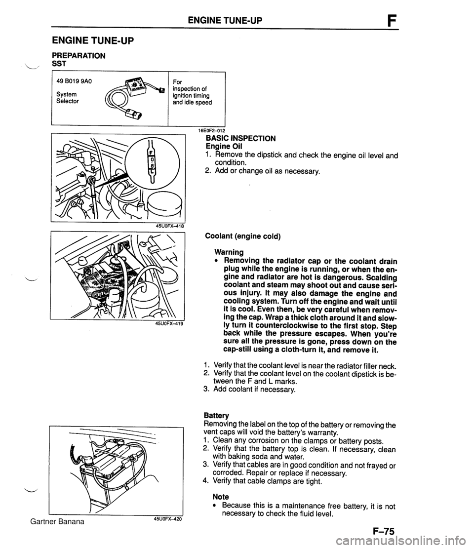
ENGINE TUNE-UP ENGINE TUNE-UP PREPARATION L" SST r I I 16EOF2-012 BASIC INSPECTION Engine Oil 1. Remove the dipstick and check the engine oil level and condition. 2. Add or change oil as necessary. 49 B019 9AO System Selector Coolant (engine cold) For inspection of ignition timing and idle speed Warning Removing the radiator cap or the coolant drain plug while the engine is running, or when the en- gine and radiator are hot is dangerous. Scalding coolant and steam may shoot out and cause seri- ous injury. It may also damage the engine and cooling system. Turn off the engine and wait until it is cool. Even then, be very careful when remov- ing the cap. Wrap a thick cloth around it and slow- ly turn it counterclockwise to the first stop. Step back while the pressure escapes. When you're sure all the pressure is gone, press down on the cap-still using a cloth-turn it, and remove it. 1. Verify that the coolant level is near the radiator filler neck. 2. Verify that the coolant level on the coolant dipstick is be- tween the F and L marks. 3. Add coolant if necessary. Battery Removing the label on the top of the battery or removing the vent caps will void the battery's warranty. 1. Clean any corrosion on the clamps or battery posts. 2. Verify that the battery top is clean. If necessary, clean with baking soda and water. 3. Verify that cables are in good condition and not frayed or corroded. Repair or replace if necessary. 4. Verify that cable clamps are tight. Note Because this is a maintenance free battery, it is not necessary to check the fluid level. Gartner Banana
Page 289 of 1708

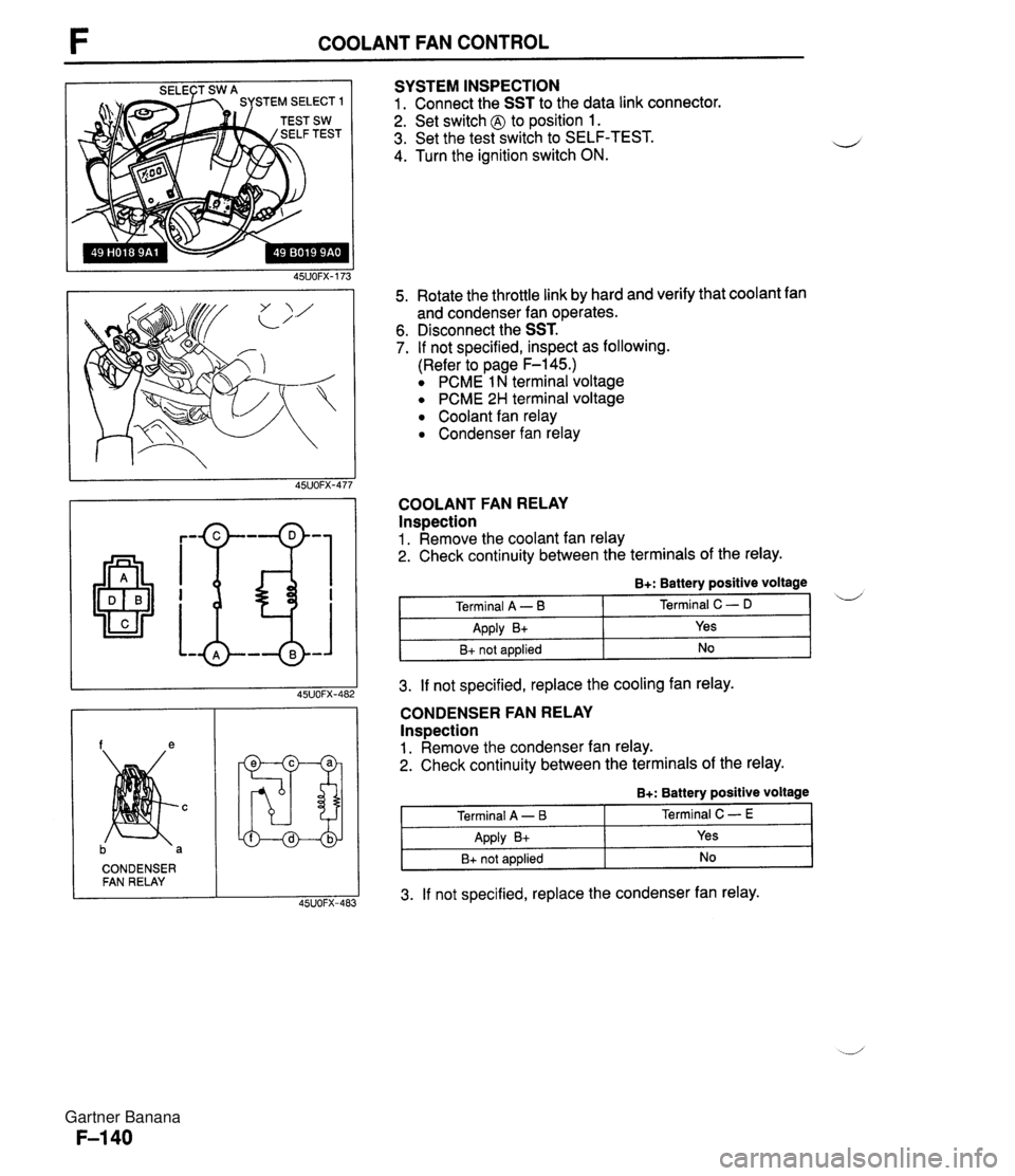
COOLANT FAN CONTROL SYSTEM INSPECTION 1. Connect the SST to the data link connector. 2. Set switch @ to position 1. 3. Set the test switch to SELF-TEST. 4. Turn the ignition switch ON. 5. Rotate the throttle link by hard and verify that coolant fan and condenser fan operates. 6. Disconnect the SST. 7. If not specified, inspect as following. (Refer to page F-145.) PCME 1 N terminal voltage PCME 2H terminal voltage Coolant fan relay Condenser fan relay COOLANT FAN RELAY lnspection 1. Remove the coolant fan relay 2. Check continuity between the terminals of the relay. CONDENSER FAN RELAY 3. If not specified, replace the cooling fan relay. B+: Battery positive voltage CONDENSER FAN RELAY Inspection 1. Remove the condenser fan relay. 2. Check continuity between the terminals of the relay. i/ Terminal A - B Apply B+ B+ not applied 3. If not specified, replace the condenser fan relay. Terminal C - D Yes No B+: Battery positive voltage Terminal A - I3 Apply B+ B+ not applied Terminal C - E Yes No Gartner Banana
Page 856 of 1708

FUSE SPECIFICATIONS Main Fuse Block u I Fuse Amperes Protected circuit HEAD INJ MAIN BTN 30A 30A COOLING FAN (AD FAN) 1 ABS I 60A I Antilock brake svstem I Headlight relay, Headlight switch Alternator, Diagnostic module (for air bag system) 80A 40A ST SIG RETRACTOR Fuse Box No.1 Except circuits protected in main fuse block: INJ 30A, HEAD 30A, RETRACTOR 30A TNS relay, Headlight switch 30A 20A EGI main relay, Coolant fan relay A/C relay 10A 30A Park l Neutral switch, Circuit-opening relay Retractable headlight actuator Fuse ENGINE METER (POWER WIND) Amperes 15A WIPER TAIL ROOM I 10A I PCME, Key reminder switch, Audio unit I Protected circuit EGI main relay, Coolant fan relay 15A 30A STOP HAZARD CIGAR 15A I Cigarette lighter, Audio unit 1 Instrument cluster, Turn signal switch, Timer and buzzer unit, Cruise control main switch Power window switch 20A 15A Fuse Box No.2 Blower switch, Wiper switch Taillights, Side marker lights, License plate lights, Parking lights 15A 15A Fuse Amperes Protected circuit I Stoplight switch, Horn switch, Cruise control unit Flasher unit Fuse Color Code (DEFOG) (ANTENNA) I Fuse amperes I Color code Fuse type 25UOTX-013 20A 20A I I 10A Red 1 I Rear window defroster Power antenna Plate type 15A 20A Light blue Yellow 30A 30A 80A Light green Pink Black Cartridge type Gartner Banana
Page 1063 of 1708

Before beginning any service procedure. refer to section T of this manual for I air bag system service warnings and audio antitheft system alarm conditions . HEATER AND AIR CONDITIONER SYSTEMS ....................................... INDEX U- 2 ................................... HEATER U- 2 AIR CONDITIONER ......................... U- 3 TROUBLESHOOTING ......................... U- 4 CIRCUIT DIAGRAM ......................... U- 4 TROUBLESHOOTING GUIDE ................ U- 5 ..................................... HEATER U-15 ........................ STRUCTURAL VIEW U-15 HEATER UNIT .............................. U-16 BLOWER UNIT ............................. U-18 HEATER CONTROL UNIT .................... U-20 AIR CONDITIONER ........................... U-23 PREPARATION ............................. U-23 STRUCTURAL Vl EW ........................ U-23 SERVICE WARNINGS ....................... U-24 SERVICE CAUTIONS ........................ U-24 REFRIGERANT SYSTEM SERVICE PROCEDURE .............................. U-25 COOLING UNIT ............................. U-30 CONDENSER AND RECEIVER DRIER ........ U-33 REFRIGERANT LINES ....................... U-35 CONDENSER FAN .......................... U-36 AIC RELAY ................................. U-37 ................... CONDENSER FAN RELAY U-37 REFRIGERANT PRESSURE SWITCH ......... U-37 NC COMPRESSOR ......................... U-38 45U0Ux-001 Gartner Banana
Page 1065 of 1708

INDEX u AIR CONDITIONER 1. Cooling unit 5. Condenser fan relay ................... Removal 1 Installation ......... page U-30 Inspection page U-37 Disassembly I Assembly ...... page U-31 6. A/C compressor 2. Condenser Removal 1 Installation ......... page U-38 ...... Removal I Installation ......... page U-33 Disassembly I Assembly page U-41 3. Receiver drier 7. Magnetic clutch Removal I Installation ......... page U-33 Disassembly 1 Assembly ...... page U-39 4. AIC relay Inspection ................... page U-37 Gartner Banana
Page 1067 of 1708

TROUBLESHOOTING u TROUBLESHOOTING GUIDE I Symptom Blower motor does not operate Reference page Below Magnetic clutch does not operate I U-7 Condenser fan does not operate e Symptom: Blower motor does not operate I U-9 Insufficient cooling No cooling Intermittent cooling Normal operation of blower motor Blower motor speed is controlled by the fan switch and a resistor in the blower unit. When the fan switch L is in the OFF position, the motor ground circuit is open and the blower motor does not operate. When the switch is in the first (Low) position, current flow from the blower motor is restricted by the three resis- tors in the resistor, and the blower motor turns at low speed. Changing the fan switch to the second (Mid), third (high), or fourth (Super-high) position causes the cir- cuit resistance to decrease, and the blower motor speed becomes correspondingly faster. I l U-10 (-1 (rn) I I I RESET BUTTON FUSE BLOCK Step 1 1. Check the circuit breaker. 2. If the reset button is not out, go to Step 2. 3. If the reset button is out, check for a short circuit in the harness. Repair as necessary; then depress the reset button to reset the circuit breaker. circuit breaker HEATER Step 2 1. Turn the ignition switch to ON. 2. Turn the fan switch to the fourth position. 3. Measure the voltage at the A terminal wire of the blower motor connector. B+: Battery positive voltage I Terminal I Voltage Action I Amperage 30A Location Fuse block A U-5 Bt Other Go to Step 3 Repair wiring harness (Circuit breaker - Blower motor) Gartner Banana
Page 1072 of 1708

TROUBLESHOOTING I ltem 1 Symptom Symptom: lnsuff icient cooling No cooling Intermittent cooling Ill Bubbles present in sight glass u Immediately after air conditioner turned off, refrigerant in sight glass stavs clear I. When air conditioner turned off, re- frigerant foams, and then sight glass becomes clear No bubbles present in sight glass Step 1 Checking refrigerant charge 1. Run the engine at a fast idle. 2. Operate the air conditioner at maximum cooling for a few minutes. 3. Observe the sight glass to determine the amount of re- frigerant and the related action as shown below. Amount of refrigerant Action Insufficient refrigerant Too much or proper amount of refrig- erant Too much refrigerant Step 2 Checking refrigerant pressure 1. Connect the manifold gauge set. 2. Operate the engine at 1,500 rpm and set the air condi- tioner to maximum cooling. 3. Measure the refrigerant pressure. 1 Proper amount of refrigerant Normal pressure Low-pressure side: 0.1 5-4.24 MPa (1.5--2.5 kgf/cm2, 22--35 psi) High-pressure side: 1.38-1.56 MPa (1 4.0-1 6.0 kgf/cm2, 200-227 psi) Check refrigerant pressure, go to Step 2 Turn air conditioner off, and watch bubbles (Refer to Items 3 and 4) Check refrigerant pressure, go to Step 2 Refrigerant amount normal 4. If the pressures not as specified, refer to the chart on the next page and check the system. ,d Gartner Banana
Page 1073 of 1708

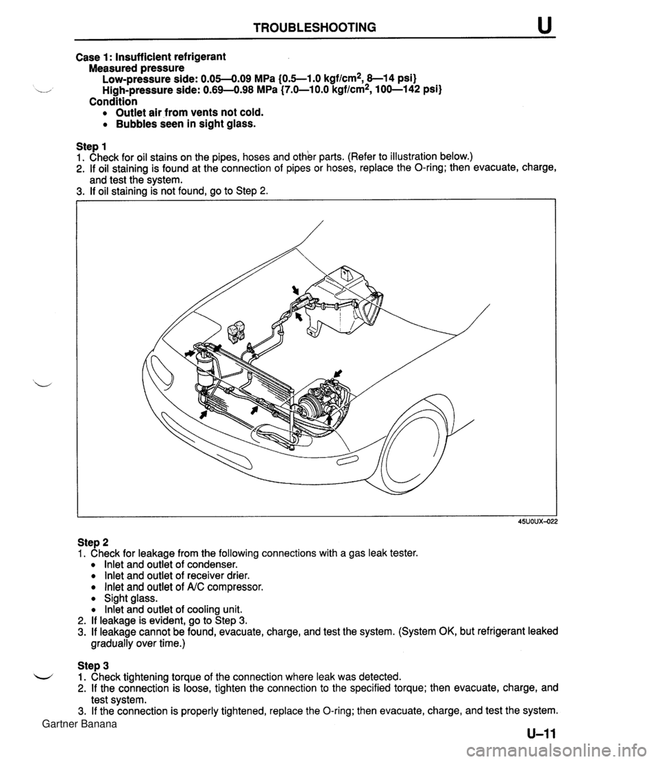
TROUBLESHOOTING Case 1: Insufficient refrigerant Measured pressure Low-pressure side: 0.05-4.09 MPa (0.5--1.0 kgf/cm2, 8-1 4 psi) u High-pressure side: 0.69-498 MPa (7.0-1 0.0 kgflcm2, 100-142 psi) Condition Outlet air from vents not cold. Bubbles seen in sight glass. Step 1 1. Check for oil stains on the pipes, hoses and other parts. (Refer to illustration below.) 2. If oil staining is found at the connection of pipes or hoses, replace the O-ring; then evacuate, charge, and test the svstem. 3. If oil staining k not found, go to Step 2. Step 2 1. Check for leakage from the following connections with a gas leak tester. lnlet and outlet of condenser. lnlet and outlet of receiver drier. lnlet and outlet of A.C compressor. Sight glass. lnkt and outlet of cooling unit. 2. If leakage is evident, go to Step 3. 3. If leakage cannot be found, evacuate, charge, and test the system. (System OK, but refrigerant leaked gradually over time.) Step 3 L-/ 1. Check tightening torque of the connection where leak was detected. 2. If the connection is loose, tighten the connection to the specified torque; then evacuate, charge, and test system. 3. If the connection is properly tightened, replace the O-ring; then evacuate, charge, and test the system. Gartner Banana