jump start MAZDA MX-5 1994 Workshop Manual
[x] Cancel search | Manufacturer: MAZDA, Model Year: 1994, Model line: MX-5, Model: MAZDA MX-5 1994Pages: 1708, PDF Size: 82.34 MB
Page 166 of 1708

TROUBLESHOOTING GUIDE SYMPTOM TROUBLESHOOTING 2 CRANKS NORMALLY BUT WILL NOT START (NO COMBUSTION) Engine cranks at normal speed but shows no sign of "firing" ESCwPTION : Battery in normal condition Throttle valve not held wide open throttle while cranking Fuel in tank rROUBLESHOOTlNG HINTS] ecause of no combustion, possibly no fuel is injected to engine or no ignition at all cylinders 1 No spark O Low fuel line pressure lanition control malfunction @ Low engine compression ignition system component malfunction I No fuel injection Fuel pump does not operate Fuel injector does not operate INSPECTION ACTION :heck if strong blue spark is visible at disconnected iigh-tension lead while cranking engine :heck if "00" is displayed on Self Diagnosis Checker ~ith ignition switch ON page F-79 Sonnect data link connector terminals F/P and GND ~ith jumper wire and check for fuel pump operating sound with ignition switch ON page F-114 Yes - No - Yes No - Yes - No Go to Step 3 Go to Step 2 Check ignition system (Refer to Troubleshooting "Misfire") mf Section G Diagnostic Trouble Code No. displayed Check for cause (Refer to specified check sequence) page F-81 "88" flashes Check PCME terminal 1 E voltage ojg. page F-145 Specification: Battery positive voltage (Ignition switch ON) 0 If OK, replace PCME us? page F-143 Q If not OK, check wiring between PCME and Self-Diagno- sis Checker page F-7 Check if engine starts in this condition 0 If starts, check fuel pump relay f@ page F-117 r3 If does not start, go to Step 5 Go to Step 4 Gartner Banana
Page 168 of 1708

TROUBLESHOOTING GUIDE 3 CRANKS NORMALLY BUT WILL NOT START (PARTIAL COMBUSTION) -WHEN ENGINE IS COLD Engine cranks at normal speed but shows partial combustion and will not continue to run IESCRIPTION Battery in normal condition Fuel in tank TROUBLESHOOTING HINTS] B AirIFue! mixture too rich Q Low engine compression Air cleaner element clogged D AirIFuel mixture too lean Fuel injection control malfunction (Correction for coolant temperature) Low fuel line pressure Air leakage of intake air system 1 INSPECTION ACTION :heck if "00" is displayed on Self-Diagnosis Checker ~ith ignition switch ON as page F-79 Sheck if strong blue spark is visible at each discon- iected high-tension lead while cranking engine Connect data link connector terminals F/P and GND with jumper wire and check for correct fuel line pres- sure with ignition switch ON E+T page F-110 Fuel Line pressure: 265--314 kPa I2.7-3.2 kgf/cm2, 38-46 psi) INSTALL CLAPS ' Yes Yes Yes - No - Go to next step Diagnostic Trouble Code No. displayed Check for cause (Refer to specified check sequence) page F-81 "88" flashes Check PCME terminal 1 E voltage @f page F-145 Specification: Battery positive voltage (Ignition switch ON) O If OK, replace PCME page F-143 L:, If not OK, check wiring between PCME and Self-Diagno- sis Checker page F-7 Go to next step Check ignition system (Refer to Troubleshooting "Misfire") Section G Go to next step Low pressure Check fuel line pressure while pinching fuel return hose If fuel line pressure quickly increases, check pressure regulator page F-118 o If fuel line pressure gradually increases, check for clog- ging between fuel pump and pressure regulator If not clogged, check fuel pump maximum pressure page F-115 High pressure Check if fuel return hose is clogged or restricted O If OK, replace pressure regulator page F-119 s If not OK, repair or replace Gartner Banana
Page 170 of 1708
![MAZDA MX-5 1994 Workshop Manual TROUBLESHOOTING GUIDE 7 CRANKS NORMALLY BUT WILL NOT START (PARTIAL COMBUSTION) -AFTER WARM-UP I ~ngine starts normally when cold TROUBLESHOOTING HINTS] D AirIFuel mixture too rich O Vapor lock Fuel p MAZDA MX-5 1994 Workshop Manual TROUBLESHOOTING GUIDE 7 CRANKS NORMALLY BUT WILL NOT START (PARTIAL COMBUSTION) -AFTER WARM-UP I ~ngine starts normally when cold TROUBLESHOOTING HINTS] D AirIFuel mixture too rich O Vapor lock Fuel p](/img/28/57072/w960_57072-169.png)
TROUBLESHOOTING GUIDE 7 CRANKS NORMALLY BUT WILL NOT START (PARTIAL COMBUSTION) -AFTER WARM-UP I ~ngine starts normally when cold TROUBLESHOOTING HINTS] D AirIFuel mixture too rich O Vapor lock Fuel pressure not held in fuel line after engine stops High RVP (winter) fuel used in warm weather 'ESCRIPTIoN Fuel injection control malfunction (Correction for coolant temperature) Fuel injector fuel leakage I INSPECTION Engine cranks at normal speed but shows partial combustion and will not continue to run after running and hol soaked Battery in normal condition :heck if "00" is displayed on Self-Diagnosis Checker with ignition switch ON @S page F-79 :heck if PCME terminal voltages are OK :2D and 20) page F-136 sonnect data link connector terminals F/P and GND ~ith jumper wire and check for correct fuel line pres- sure with ignition switch ON page F-110 Fuel Line pressure: 26-14 kPa {2.7-3.2 kgflcm2, 38-46 psi) GND F~P INSTALL CLAPS ' Yes No - Yes - No Yes ACTION Go to next step Diagnostic Trouble Code No. displayed Check for cause (Refer to specified check sequence) page F-81 "88" flashes Check PCME terminal 1 E voltage page F-145 Specification: Battery positive voltage (Ignition switch ON) 0 If OK, replace PCME page F-143 0 If not OK, check wiring between PCME and Self-Diagno- sis Checker page F-7 Go to next step Check for cause (Refer to "Check Point for Each Terminal") page F-148 Go to next step Low pressure Check fuel line pressure while pinching fuel return hose Q If fuel line pressure quickly increases, check pressure regulator page F-118 0 If fuel line pressure gradually increases, check fuel line and filter for clogging If not clogged, check fuel pump maximum pressure page F-115 - High pressure Check if fuel return hose is clogged or restricted a If OK, replace pressure regulator page F-119 6 If not OK, repair or replace Gartner Banana
Page 257 of 1708

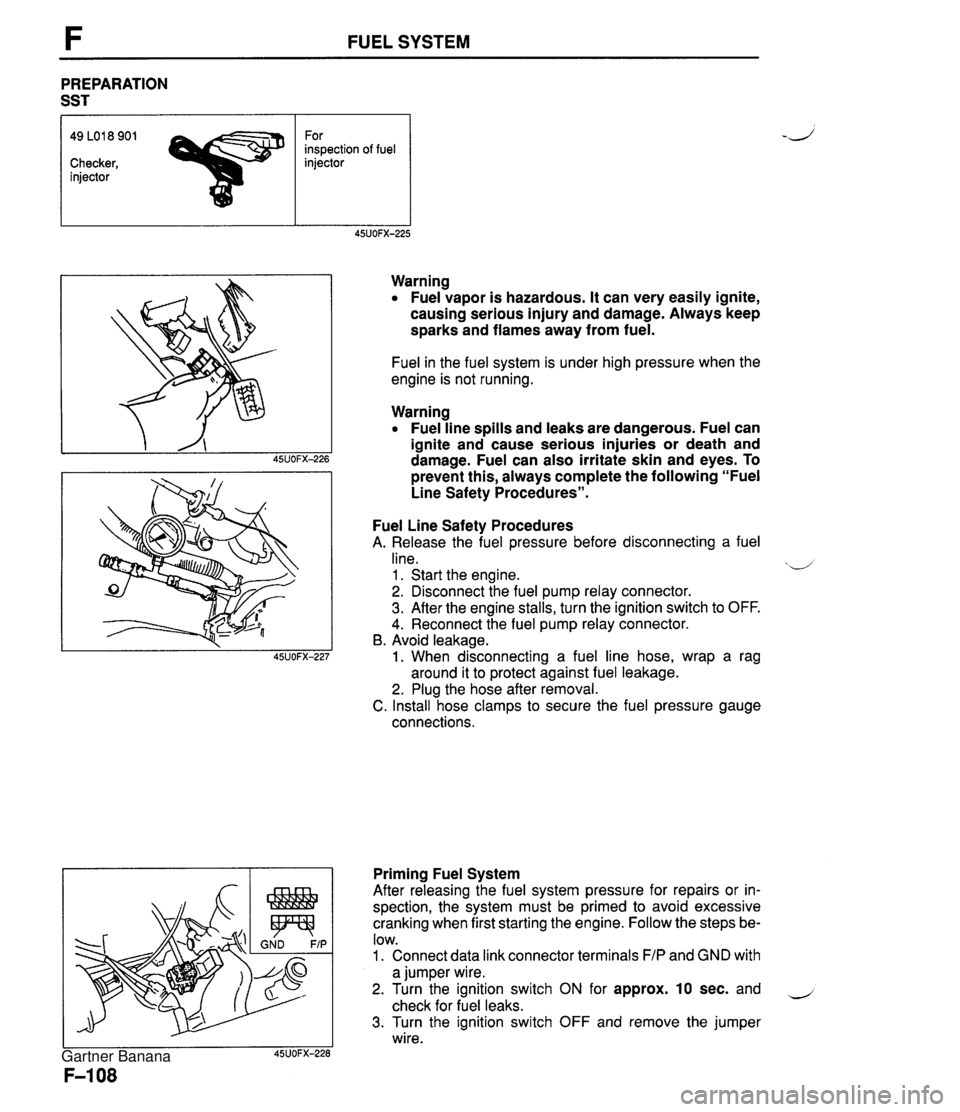
FUEL SYSTEM PREPARATION SST 49 LO1 8 901 For inspection of fuel Checker, injector injector Warning Fuel vapor is hazardous. It can very easily ignite, causing serious injury and damage. Always keep sparks and flames away from fuel. Fuel in the fuel system is under high pressure when the engine is not running. Warning Fuel line spills and leaks are dangerous. Fuel can ignite and cause serious injuries or death and damage. Fuel can also irritate skin and eyes. To prevent this, always complete the following "Fuel Line Safety Procedures". Fuel Line Safety Procedures A. Release the fuel pressure before disconnecting a fuel line. xd 1 . Start the engine. 2. Disconnect the fuel pump relay connector. 3. After the engine stalls, turn the ignition switch to OFF. 4. Reconnect the fuel pump relay connector. B. Avoid leakage. 1. When disconnecting a fuel line hose, wrap a rag around it to protect against fuel leakage. 2. Plug the hose after removal. C. Install hose clamps to secure the fuel pressure gauge connections. Priming Fuel System After releasing the fuel system pressure for repairs or in- spection, the system must be primed to avoid excessive cranking when first starting the engine. Follow the steps be- low. 1. Connect data link connector terminals F/P and GND with a jumper wire. 2. Turn the ignition switch ON for approx. 10 sec. and - check for fuel leaks. 3. Turn the ignition switch OFF and remove the jumper wire. Gartner Banana
Page 267 of 1708

F FUEL SYSTEM PRESSURE REGULATOR Inspection Fuel line pressure d Warning Fuel line spills and leaks can be dangerous. Fuel can ignite and cause serious injuries or death and can damage the vehicle. Fuel can also irritate skin and eyes. To prevent this from happening, release the fuel pressure according to "Fuel Line Safety Procedures" on page F-108. 1. Disconnect the negative battery terminal. 2. Connect a fuel pressure gauge between the fuel main pipe and the fuel main hose. (Install clamps as shown.) 3. Connect the negative battery terminal. 4. Start the engine and run it at idle. 5. Measure the fuel line pressure. Fuel line pressure: 21 6-264 kPa (2.2-2.7 kgf/cm2, 32-38 psi) Hold pressure Perform this inspection if the fuel pressure hold inspec- tion is not as specified. (Refer to page F-104.) Warning Fuel line spills and leaks can be dangerous. Fuel ,-, can ignite and cause serious injuries or death and can damage the vehicle. Fuel can also irritate skin and eyes. To prevent this from happening, release the fuel pressure according to "Fuel Line Safety Procedures" on page F-108. 1. Disconnect the negative battery terminal. 2. Install a fuel pressure gauge between the fuel pipe and the fuel main hose. (Install clamps as shown.) 3. Connect the negative battery terminal. 4. Connect data link connector terminals F/P and GND with a jumper wire. 5. Turn the ignition switch ON for 10 sec. to operate the fuel pump. 6. Turn the ignition switch OFF and disconnect the jumper wire. 7. Block the outlet of the pressure regulator. 8. Observe the fuel pressure for 5 min. Fuel pressure: More than 147 kPa {I .5 kgf/cm2, 21 psi) 9. If pressure is as specified, replace the pressure regula- tor. Gartner Banana
Page 272 of 1708

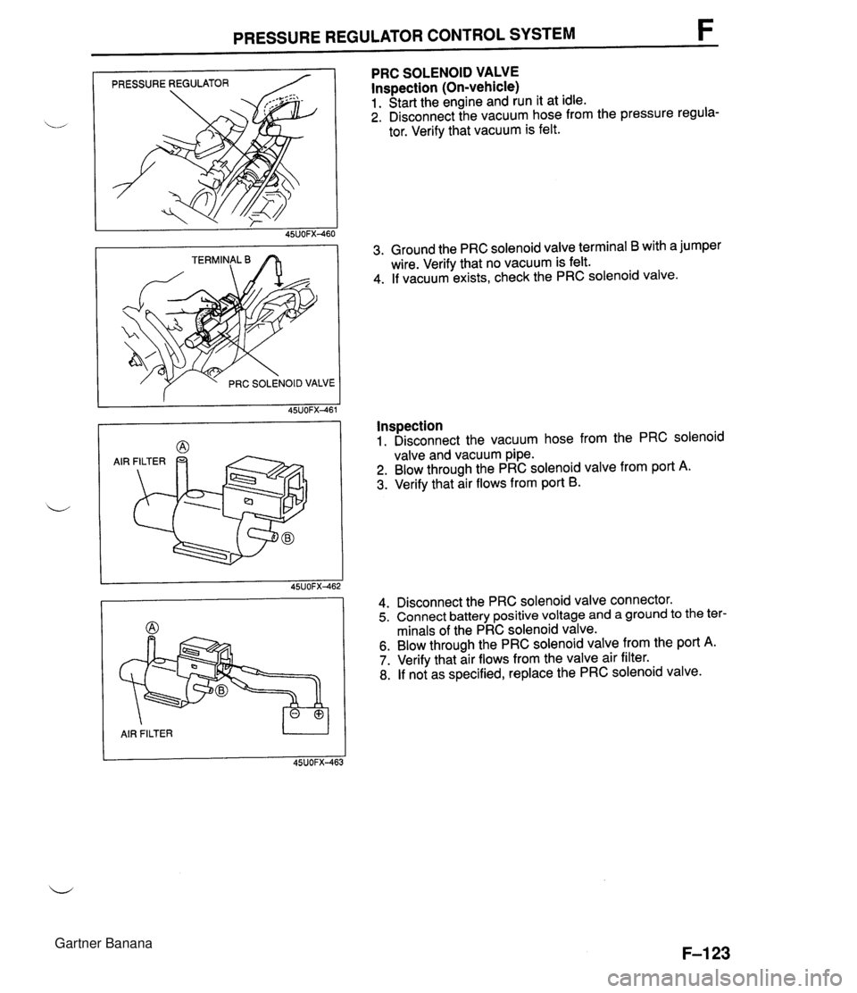
PRESSURE REGULATOR CONTROL SYSTEM F PRESSURE REGULATOR / f PRC SOLENOID VALVE AIR FILTER U PRC SOLENOID VALVE lnspection (On-vehicle) 1. Start the engine and run it at idle. 2. Disconnect the vacuum hose from the pressure regula- tor. Verify that vacuum is felt. 3. Ground the PRC solenoid valve terminal B with a jumper wire. Verify that no vacuum is felt. 4. If vacuum exists, check the PRC solenoid valve. Inspection 1. Disconnect the vacuum hose from the PRC solenoid valve and vacuum pipe. 2. Blow through the PRC solenoid valve from port A. 3. Verify that air flows from port B. 4. Disconnect the PRC solenoid valve connector. 5. Connect battery positive voltage and a ground to the ter- minals of the PRC solenoid valve. 6. Blow through the PRC solenoid valve from the port A. 7. Verify that air flows from the valve air filter. 8. If not as specified, replace the PRC solenoid valve. Gartner Banana
Page 274 of 1708

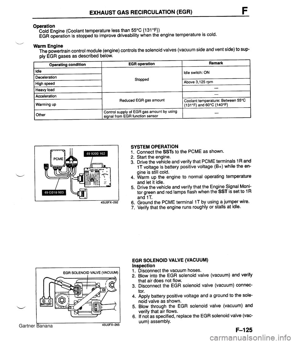
EXHAUST GAS RECIRCULATION (EGR) Operation Cold Engine (Coolant temperature less than 55°C (1 31 OF)) EGR operation is stopped to improve driveability when the engine temperature is cold. u Warm Engine The powertrain control module (engine) controls the solenoid valves (vacuum side and vent side) to sup- ply EGR gases as described below. Remark Operating condition Idle Deceleration High speed Heavy load EGR SOLENOID VALVE (VACUUM) I I EGR operation Acceleration Warming up Other SYSTEM OPERATION 1. Connect the SSTs to the PCME as shown. 2. Start the engine. 3. Drive the vehicle and verify that PCME terminals 1 R and 1 T voltage is battery positive voltage (B+) while the en- gine is still cold. 4. Warm up the engine to normal operating temperature and let it idle. 5. Drive the vehicle and verify that the Engine Signal Moni- tor green and red lamps flash when the SST is set to 1 R and 1 T. 6. Ground the PCME terminal IT by using a jumper wire. 7. Verify that the engine runs roughly or stalls at idle. Stopped EGR SOLENOID VALVE (VACUUM) Inspection 1. Disconnect the vacuum hoses. 2. Blow into the EGR solenoid valve (vacuum) and verify that air does not flow. 3. Disconnect the EGR solenoid valve (vacuum) connec- tor. 4. Apply battery positive voltage and a ground to the sole- noid valve as shown. 5. Blow through the EGR solenoid valve (vacuum) and verify that air flows. 6. If not as specified, replace the EGR solenoid valve (vac- uum) assembly. Idle switch: ON Above 3,125 rpm - Reduced EGR gas amount Control supply of EGR gas amount by using signal from EGR function sensor - Coolant temperature: Between 55OC (1 31 OF) and 60°C {140°F) - Gartner Banana
Page 884 of 1708

WARNING LIGHT AND SENDER UNIT T OHMMETER Washer Level Indicator lnspection 1. Disconnect the connector from the washer level sensor. 2. Jump terminal-wire L (harness side) to a body ground. 3. Start the engine and check that the WASHER indicator illuminates. 4. If there is no illumination, check the bulb, wiring harness, and sensor. Replace or repair as necessary. Washer Level Sensor lnspection 1. Connect the sensor connector (sensor side) to an ohm- meter. 2. Move the sensor float up and down. 3. Verify that there is continuity when the float is at the low- est point. BRAKE FLUID LEVEL SENSOR lnspection 1. Check for continuity of the sensor. 2. If continuity is not as specified, replace the level sensor. Float level Below MIN Above MIN BUCKLE SWITCt Continuity Yes No OHMMETER -1 PARKING BRAKE SWITCH lnspection 1. Disconnect the parking brake switch connector. 2. Check for continuity between the switch connector and ground. I Lever I Continuity I 3. If continuity is not as specified, adjust or replace the parking brake switch. (Refer to section P.) Pulled one notch Released BUCKLE SWITCH lnspection 1. Disconnect the buckle switch connector 2. Check for continuity of the switch. Yes No Seat belt I Continuity Seat belt buckled Seat belt unbuckled No Yes 3. If continuity is not as specified, replace the buckle switch. Gartner Banana