MAZDA MX-5 1994 Workshop Manual
Manufacturer: MAZDA, Model Year: 1994, Model line: MX-5, Model: MAZDA MX-5 1994Pages: 1708, PDF Size: 82.34 MB
Page 371 of 1708

TRANSMISSION 1. Snap ring 2. Washer 3. Retaining ring b 4. C-washer 5. Mainshaft rear bearing Disassembly Note . below Inspection ... page J-25 6. Retaining ring 7. C-washer 8. Thrust lock washer 9. Steel ball 10. Locknut (Countershaft) Disassembly Note ................ below 11. Countershaft rear bearing Disassembly Note ........... page J-18 Inspection ... page J-25 12. Counter 5th gear Inspection ... page J-23 13. Spacer 14. 5th gear 15. 5th synchronizer ring Inspection ... page J-24 16. Locknut (Mainshaft) Disassembly Note ........... page J-18 17. Clutch hub assembly (5thIReverse) Inspection ... page J-23 18. Reverse synchronizer ring Inspection ... page J-24 19. Reverse gear Inspection ... page J-23 20. Bearing Inspection ... page J-25 21. Bearing race 22. Washer 23. Counter reverse gear Inspection ... page J-23 24. Main drive gear bearing Disassembly Note ........... page J-18 Inspection ... page J-25 26. Countershaft front bearing Disassembly Note ........... page J-18 Inspection ... page J-25 27. Bearing housing assembly Disassembly Note ........... page J-18 Disassembly page J-20 28. Mainshaft gear assembly 29. Main drive gear Inspection ... page J-23 30. 4th synchronizer ring Inspection ... page J-24 31. Bearing Inspection ... page J-25 32. Washer 33. Countershaft Inspection ... page J-23 34. Spacer 35. Synchronizer key springs 36. Clutch hub sleeve 37. Synchronizer key . . Inspection ... page J-23 25. Snap ring 38. Clutch hub 45UOJX-012 Disassembly note Mainshaft rear bearing Remove the mainshaft rear bearing by using the SST. Locknut (Countershaft) 1. Shift the clutch hub sleeves into 1 st and Reverse gears to lock the rotation of the mainshaft. 2. Use a suitable tool to uncrimp the tabs of the locknut. 3. Connect the SST to the mainshaft and secure it in a vise. 4. Remove the locknut. Gartner Banana
Page 372 of 1708
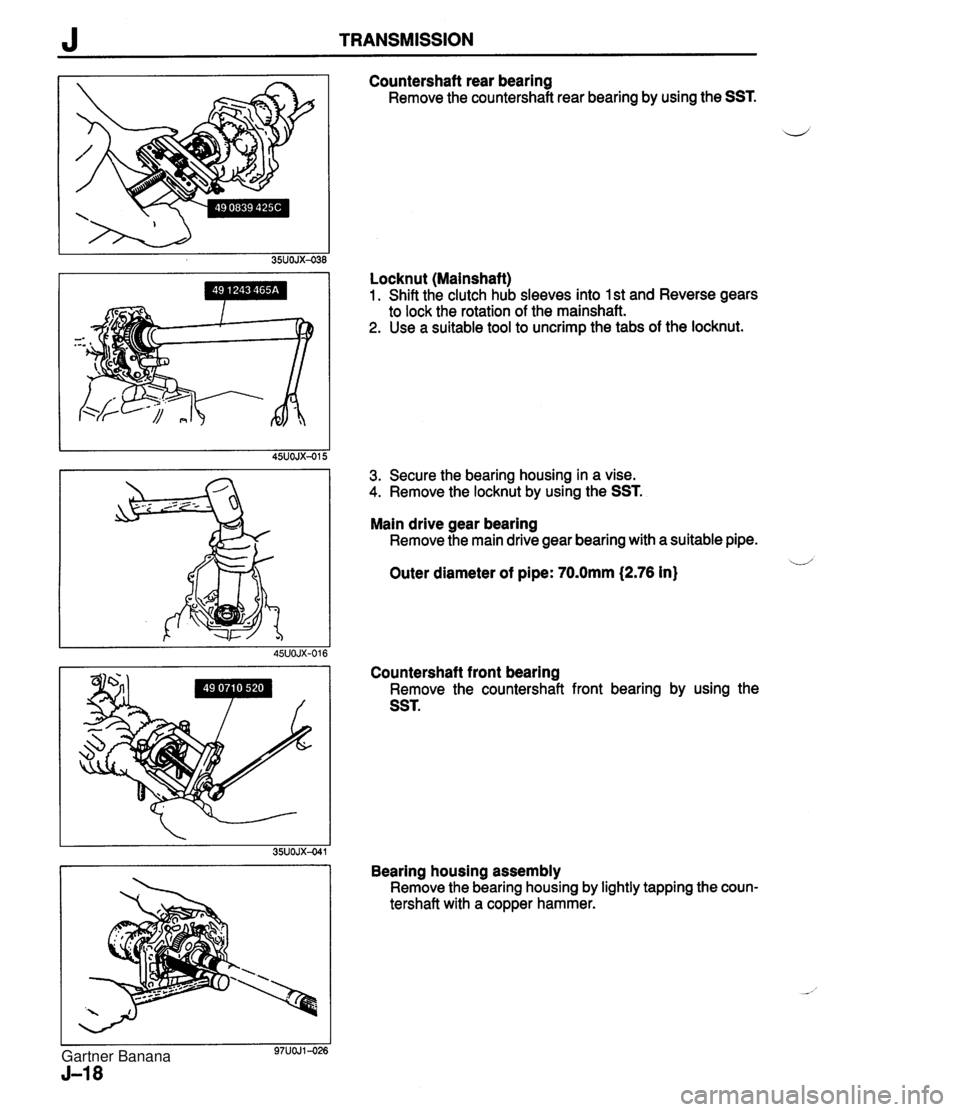
J TRANSMISSION Countershaft rear bearing Remove the countershaft rear bearing by using the SST. i/ Locknut (Mainshaft) 1. Shift the clutch hub sleeves into 1 st and Reverse gears to lock the rotation of the mainshaft. 2. Use a suitable tool to uncrimp the tabs of the locknut. 3. Secure the bearing housing in a vise. 4. Remove the locknut by using the SST. Main drive gear bearing Remove the main drive gear bearing with a suitable pipe. u Outer diameter of pipe: 70.0mm (2.76 in) Countershaft front bearing Remove the countershaft front bearing by using the SST. Bearing housing assembly Remove the bearing housing by lightly tapping the coun- tershaft with a copper hammer. Gartner Banana
Page 373 of 1708

TRANSMISSION J Mainshaft Parts Disassemble in the order shown in the figure, referring to Disassembly Note. 1. 1st gear 10. Synchronizer assembly (2nd) Inspection ................... page J-23 lnspection ................... page J-24 2. Bearing 11. Inner cone Inspection ................... page J-25 12. Double cone 3. Bearing race 13. 2nd synchronizer ring 4. 1st synchronizer ring Inspection ................... page J-24 Inspection ................... page J-24 14. 2nd gear 5. Snap ring Inspection ................... page J-23 6. Clutch hub assembly (3rdl4th) 15. Mainshaft Disassembly Note ............ page J-20 Inspection ................... page J-23 Inspection ................... page J-23 16. Synchronizer key springs 7. 3rd synchronizer ring 17. Clutch hub sleeve Inspection ................... page J-24 18. Synchronizer key 8. 3rd gear 19. Clutch hub ................... u Inspection page J-23 9. Clutch hub assembly (1 stl2nd) Disassembly Note ............ page J-20 Inspection ................... page J-23 Gartner Banana
Page 374 of 1708
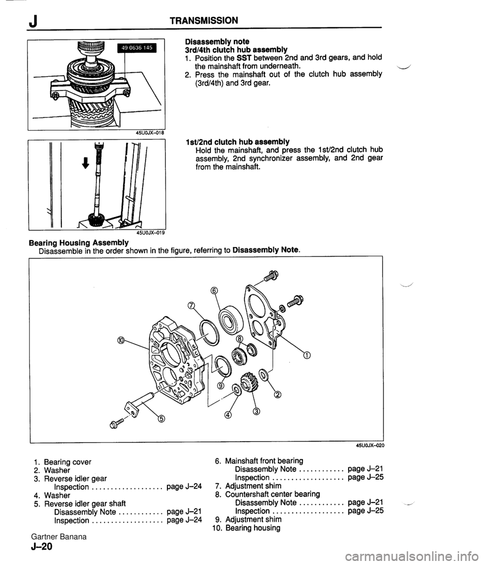
J TRANSMISSION Disassembly note 3rdl4th clutch hub assembly 1. Position the SST between 2nd and 3rd gears, and hold the mainshaft from underneath. 4 2. Press the mainshaft out of the clutch hub assembly (3rdl4th) and 3rd gear. 1 st12nd clutch hub assembly Hold the mainshaft, and press the lstJ2nd clutch hub assembly, 2nd synchronizer assembly, and 2nd gear from the mainshaft. Bearing Housing Assembly Disassemble in the order shown in the figure, referring to Disassembly Note. 1 . Bearing cover 6. Mainshaft front bearing 2. Washer Disassembly Note ............ page J-21 3. Reverse idler gear Inspection ................... page J-25 Inspection ................... page J-24 7. Adjustment shim 4. Washer 8. Countershaft center bearing 5. Reverse idler gear shaft Disassembly Note ............ page J-21 - Disassembly Note ............ page J-21 Inspection ................... page J-25 Inspection ................... page J-24 9. Adjustment shim 10. Bearing housing Gartner Banana
Page 375 of 1708
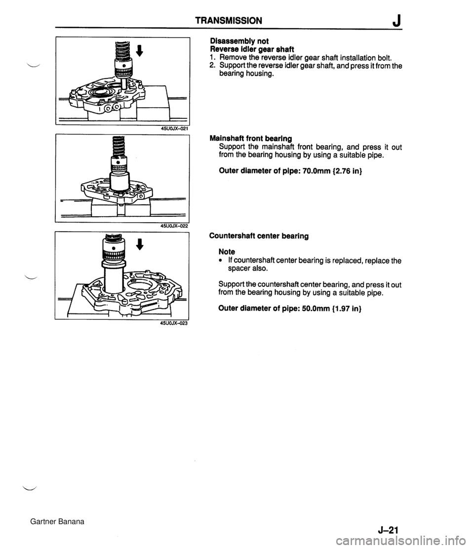
TRANSMISSION J Disassembly not Reverse idler gear shaft 1. Remove the reverse idler gear shaft installation bolt. 2. Support the reverse idler gear shaft, and press it from the bearing housing. Mainshaft front bearing Support the mainshaft front bearing, and press it out from the bearing housing by using a suitable pipe. Outer diameter of pipe: 70.0mm (2.76 in} Countershaft center bearing Note If countershaft center bearing is replaced, replace the spacer also. Support the countershaft center bearing, and press it out from the bearing housing by using a suitable pipe. Outer diameter of pipe: 50.0mm (1.97 in} Gartner Banana
Page 376 of 1708

J TRANSMISSION Extension Housing Parts Disassemble in the order shown in the figure. REPLACE 1. Steel ball, spring, and spring cap 8. Change bushing 2. Select-lock spindle, spring, and spring cap 9. Wave washer 3. Plug, spring, and pushpin 10. Change control case 4. Blind cover 11. Rod cover 5. Roll pin 12. Oil passage 6. Control rod 13. Oil seal 7. Control rod end Do not remove unless necessary Gartner Banana
Page 377 of 1708

TRANSMISSION J INSPECTION lnspect all parts and repair or replace as necessary. Each Gear and Main Drive Gear 1, lnspect synchronizer cones for wear. 2. lnspect individual gear teeth for damage, wear, and cracks. 3. lnspect synchronizer ring matching teeth for damage and wear. 4. lnspect main drive gear splines for damage and wear. MEASUREMENT POINTS 35UOJX-046 Mainshaft 1. Measure the mainshaft runout as shown. Maximum runout: 0.03mm (0.0012 in} 2. lnspect splines for damage or wear. 3. Measure the clearance between mainshaft and gear (or bushing). Maximum clearance: 0.15mm (0.006 in} Countershaft 1. lnspect gear teeth for damage, wear, and cracks. 2. lnspect splines for damage and wear. Clutch Hub Assembly 1. lnspect clutch hub sleeve and hub operation. 2. lnspect individual gear teeth for damage, wear, and cracks. 3. lnspect synchronizer keys for damage, wear, and cracks. Gartner Banana
Page 378 of 1708
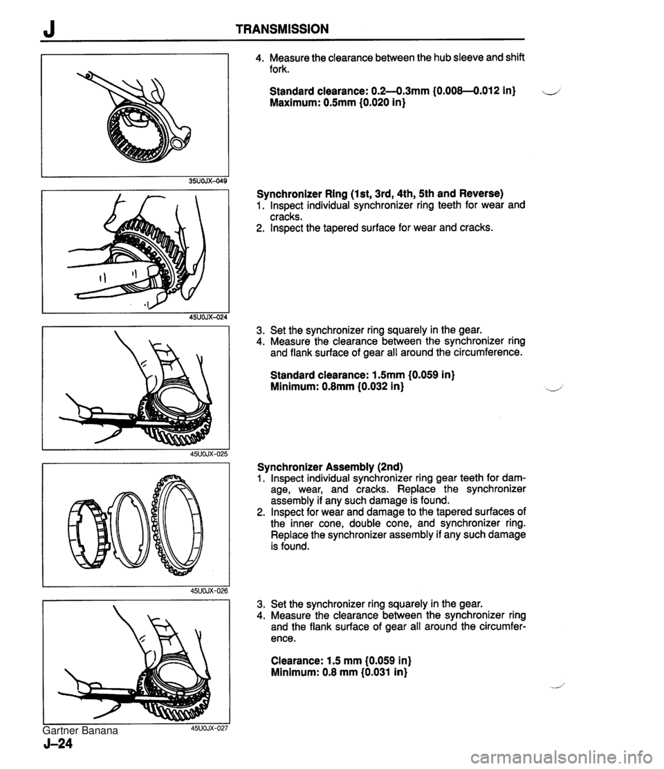
J TRANSMISSION 4. Measure the clearance between the hub sleeve and shift fork. Standard clearance: 0.2--0.3mm (0.008--0.012 in) ii Maximum: 0.5mm (0.020 in) Synchronizer Ring (Ist, 3rd, 4th, 5th and Reverse) 1. lnspect individual synchronizer ring teeth for wear and cracks. 2. lnspect the tapered surface for wear and cracks. 3. Set the synchronizer ring squarely in the gear. 4. Measure the clearance between the synchronizer ring and flank surface of gear all around the circumference. Standard clearance: 1.5mm (0.059 in) Minimum: 0.8mm (0.032 in) Synchronizer Assembly (2nd) 1. lnspect individual synchronizer ring gear teeth for dam- age, wear, and cracks. Replace the synchronizer assembly if any such damage is found. 2. lnspect for wear and damage to the tapered surfaces of the inner cone, double cone, and synchronizer ring. Replace the synchronizer assembly if any such damage is found. Set the synchronizer ring squarely in the gear. Measure the clearance between the synchronizer ring and the flank surface of gear all around the circumfer- ence. Clearance: 1.5 mm (0.059 in) Minimum: 0.8 mm (0.031 in) Gartner Banana
Page 379 of 1708
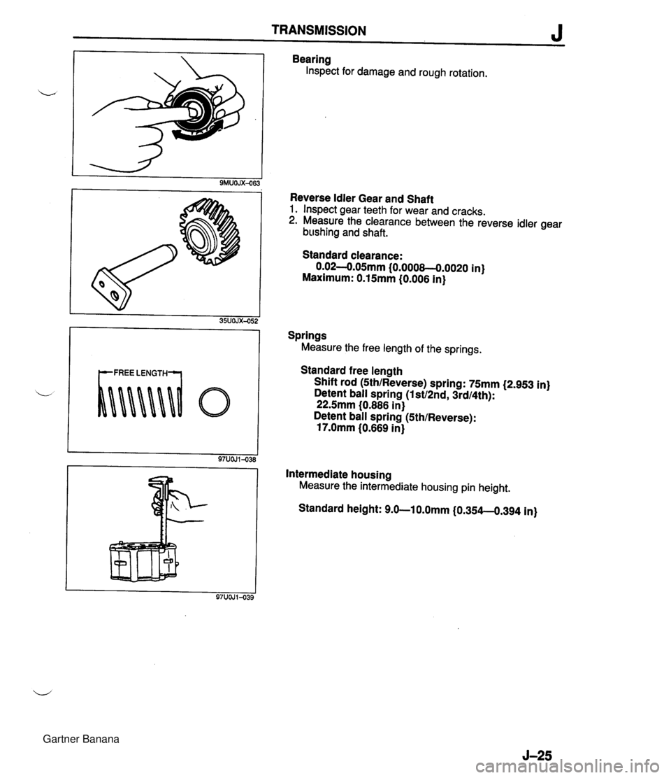
TRANSMISSION J Bearing Inspect for damage and rough rotation. Reverse Idler Gear and Shaft 1. Inspect gear teeth for wear and cracks. 2. Measure the clearance between the reverse idler gear b~~shing and shaft. Standard clearance: 0.02-0.05mm {0.000&-0.0020 in) Maximum: 0.15mm (0.006 in) Springs Measure the free length of the springs. Standard free length Shift rod (Sth/Reverse) spring: 75mm (2.953 in) Detent ball spring (lst/2nd, 3rdI4th): 22.5mm (0.886 in) Detent ball spring (Sth/Reverse): 17.0mm (0.669 in) Intermediate housing Measure the intermediate housing pin height. Standard height: 9.0-10.0mm (0.354-0.394 in) Gartner Banana
Page 380 of 1708

J TRANSMISSION ASSEMBLY Precaution 1. All O-rings and gaskets must be replaced with the new ones included in the overhaul kit. 2. Before assembly, make sure all parts are completely clean. 4 3. Assemble the parts within 10 minutes after applying sealant. Allow all sealant to cure at least 30 minutes after assembly before filling the transmission with transmission oil. 35UOJX-053 (5TH) (REVERSE) (~RD, 4TH) (1 ST, 2ND) 45UOJX-029 Clutch hub For the synchronizer assemblies, align the synchronizer ring grooves and synchronizer keys. The synchronizer rings can be distinguished as shown in the figure. The inner diametes of the 2nd synchronizer ring is larger than the 1 st. When installing the gears and clutch hub assemblies in the following procedure, make sure that they are installed in the direction shown in the figure. Gartner Banana