power steering MAZDA MX-5 1994 Workshop Manual
[x] Cancel search | Manufacturer: MAZDA, Model Year: 1994, Model line: MX-5, Model: MAZDA MX-5 1994Pages: 1708, PDF Size: 82.34 MB
Page 9 of 1708
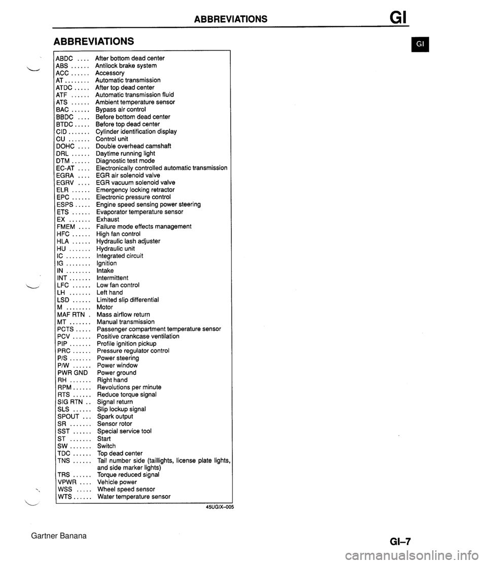
ABBREVIATIONS 4BDC .... 4BS ...... 4CC ...... 4T ........ 4TDC ..... 4TF ...... 4TS ...... 3AC ...... 3BDC .... 3TDC ..... :ID ....... 2U ....... IOHC .... IRL ...... ITM ...... IC-AT .... iGRA .... EGRV .... ELR ...... EPC ...... ESPS ..... ETS ...... EX ....... FMEM .... HFC ...... HLA ...... H U ....... IC ........ IG ........ IN ........ INT ....... LFC ...... LH ....... LSD ...... M ........ MAF RTN . MT ....... PCTS ..... PCV ...... PIP ....... PRC ...... PIS ....... PMI ...... PWR GND RH ....... RPM ...... RTS ...... SIG RTN . . SLS ...... ... SPOUT S R ....... SST ...... ST ....... SW ....... TDC ...... TNS ...... TRS ...... VPWR .... WSS ..... WTS...... After bottom dead center Antilock brake system Accessory Automatic transmission After top dead center Automatic transmission fluid Ambient temperature sensor Bypass air control Before bottom dead center Before top dead center Cylinder identification display Control unit Double overhead camshaft Daytime running light Diagnostic test mode Electronically controlled automatic transmission EGR air solenoid valve EGR vacuum solenoid valve Emergency locking retractor Electronic pressure control Engine speed sensing power steering Evaporator temperature sensor Exhaust Failure mode effects management High fan control Hydraulic lash adjuster Hydraulic unit Integrated circuit Ignition Intake Intermittent Low fan control Left hand Limited slip differential Motor Mass airflow return Manual transmission Passenger compartment temperature sensor Positive crankcase ventilation Profile ignition pickup Pressure regulator control Power steering Power window Power ground Right hand Revolutions per minute Reduce torque signal Signal return Slip lockup signal Spark output Sensor rotor Special service tool Start Switch Top dead center Tail number side (taillights, license plate lights and side marker lights) Torque reduced signal Vehicle power Wheel speed sensor Water temperature sensor Gartner Banana
Page 11 of 1708
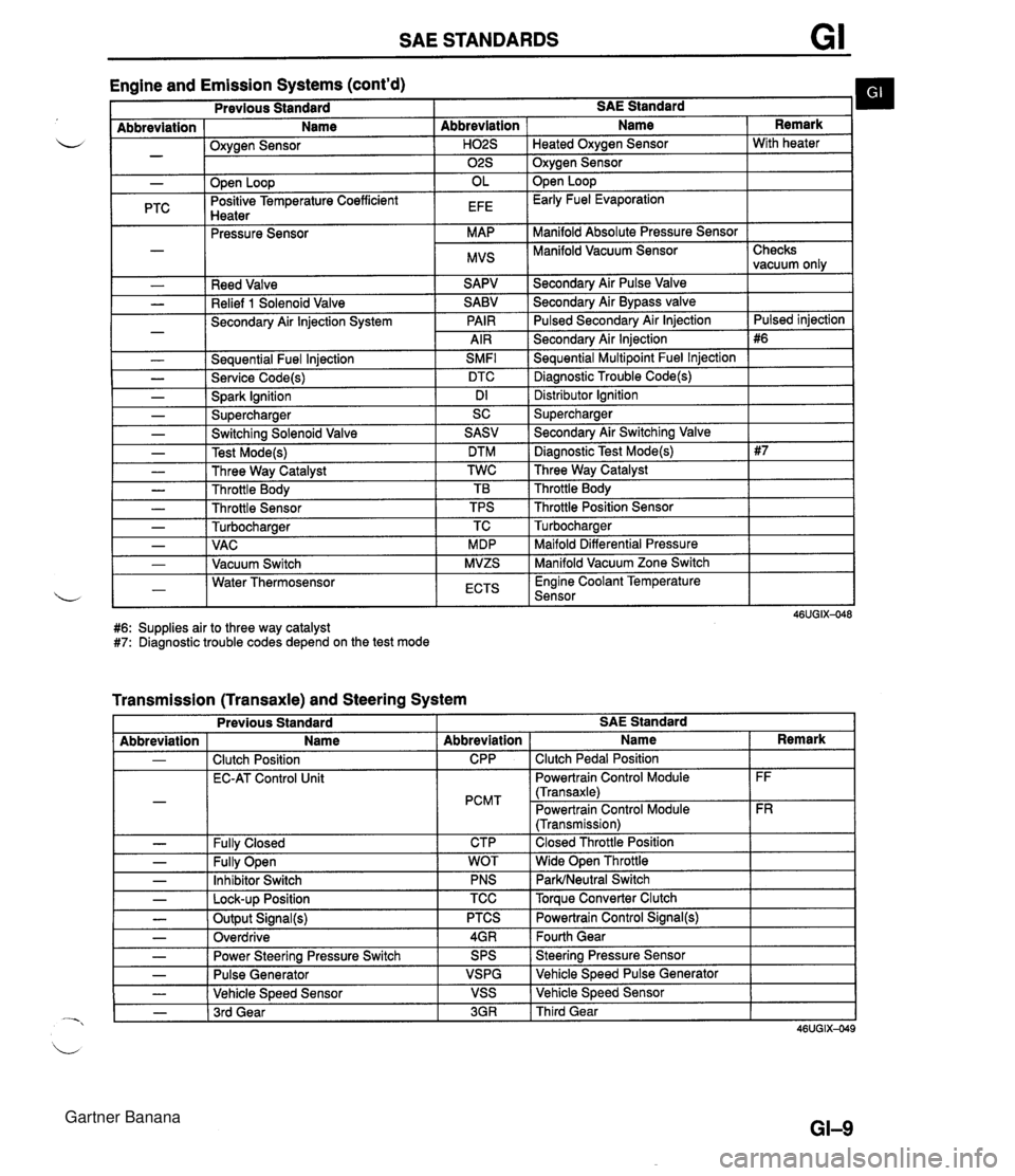
SAE STANDARDS Engine and Emission Systems (cont'd) I Previous Standard I SAE Standard b I - Abbreviation ( Name I Oxvaen Sensor - .w- - I I ." I 02s I Oxygen Sensor I - PTC Reed Valve Relief 1 Solenoid Valve Secondary Air lnjection System - Seauential Fuel lniection SMFl L - Service Code(s) DTC - Spark Ignition Dl - Supercharger SC Abbreviation I Name Open Loop Positive Temperature Coefficient Hnatar Secondarv Air Pulse Valve Remark . .--.-. Pressure Sensor Secondary Air Bypass valve Pulsed Secondarv Air lniection H02S I Heated Oxvaen Sensor I With heater OL EFE Secondary Air lnjection Sequential Multipoint Fuel lnjection Diagnostic Trouble Code(s) Open Loop Early Fuel Evaporation MAP MVS Distributor lgnition Supercharger Manifold Absolute Pressure Sensor Manifold Vacuum Sensor I - - - - - - Checks vacuum only Pulsed iniection - Switching Solenoid Valve Test Mode(s) Three Way Catalyst Throttle Body Throttle Sensor Turbocharaer .. Maifold Differential Pressure Manifold Vacuum Zone Switch , - I - 1 VAC I MDP 1-1 Water Thermosensor L - I Vacuum Switch I ECTS I Engine Coolant Temperature Sensor I SASV DTM TWC TB TPS TC MVZS #6: Supplies air to three way catalyst #7: Diagnostic trouble codes depend on the test mode - Secondary Air Switching Valve Diagnostic Test Mode(s) Three Way Catalyst Throttle Body Throttle Position Sensor Turbocharaer Transmission (Transaxle) and Steering System L - - Previous Standard I I I I Abbreviation - - - SAE Standard Fully Open Inhibitor Switch - I Lock-up Position - - Name Clutch Position EC-AT Control Unit Fullv Closed Abbreviation CPP PCMT CTP TCC I Torque Converter Clutch - - - WOT PNS Output Signal(s) Overdrive I Name Clutch Pedal Position Powertrain Control Module (Transaxle) Powertrain Control Module (Transmission) Closed Throttle Position Wide Open Throttle ParWNeutral Switch Power Steering Pressure Switch Pulse Generator Vehicle Speed Sensor - 1 3rd Gear Remark FF FR PTCS 4GR 3GR I Third Gear Powertrain Control Signal(@ Fourth Gear SPS VSPG VSS Steering Pressure Sensor Vehicle Speed Pulse Generator Vehicle Speed Sensor Gartner Banana
Page 23 of 1708
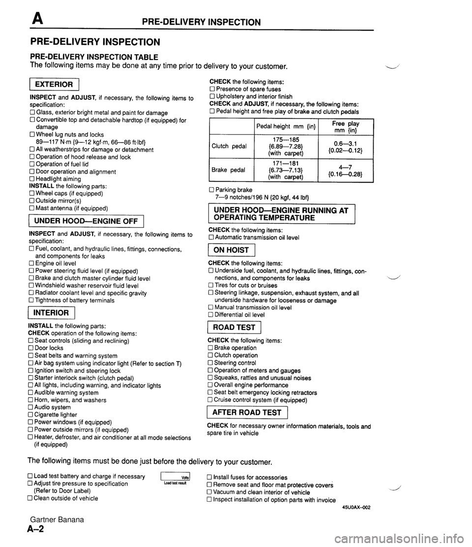
PRE-DELIVERY INSPECTION PRE-DELIVERY INSPECTION PRE-DELIVERY INSPECTION TABLE The following items may be done at any time prior to delivery to your customer. INSPECT and ADJUST, if necessary, the following items to specification: 0 Glass, exterior bright metal and paint for damage 0 Convertible top and detachable hardtop (if equipped) for damage 0 Wheel lug nuts and locks 89-117 N.m (9-1 2 kgf.m, 66-86 ft4bf) 0 All weatherstrips for damage or detachment Operation of hood release and lock Operation of fuel lid 0 Door operation and alignment Headlight aiming INSTALL the following parts: Wheel caps (if equipped) 0 Outside mirror(s) 0 Mast antenna (if equipped) UNDER HOOD-ENGINE OFF INSPECT and ADJUST, if necessary, the following items to specification : Fuel, coolant, and hydraulic lines, fittings, connections, and components for leaks Engine oil level 0 Power steering fluid level (if equipped) Brake and clutch master cylinder fluid level 0 Windshield washer reservoir fluid level 0 Radiator coolant level and specific gravity 0 Tightness of battery terminals pKiq INSTALL the following parts: CHECK operation of the following items: 0 Seat controls (sliding and reclining) 0 Door locks 0 Seat belts and warning system 0 Air bag system using indicator light (Refer to section T) Ignition switch and steering lock 0 Starter interlock switch (clutch pedal) All lights, including warning, and indicator lights 0 Audible warning system 0 Horn, wipers, and washers Audio system 0 Cigarette lighter Power windows (if equipped) 0 Power outside mirrors (if equipped) 0 Heater, defroster, and air conditioner at all mode selections (if equipped) CHECK the following items: Presence of spare fuses 0 Upholstery and interior finish CHECK and ADJUST, if necessary, the following items: 0 Pedal height and free play of brake and clutch pedals I Pedal height mm {in} I Ft: $iy I Clutch pedal {6.89--7.28) (with carpet) Parking brake 7-9 notchesil96 N (20 kgf, 44 Ibf) 0.63.1 (0.024. 12) Brake pedal RUNNING AT OPERATING TEMPERATURE CHECK the following items: 0 Automatic transmission oil level 171-181 (6.73--7.13) (with carpet) I ON HOIST I 4--7 {0.16-0.28} CHECK the following items: 0 Underside fuel, coolant, and hydraulic lines, fittings, con- nections, and components for leaks 4 Tires for cuts or bruises 0 Steering linkage, suspension, exhaust system, and all underside hardware for looseness or damage Manual transmission oil level Differential oil level I ROAD TEST I CHECK the following items: Brake operation Clutch operation 0 Steering control 0 Operation of meters and gauges Squeaks, rattles and unusual noises 0 Overall engine performance Seat belt emergency locking retractors 0 Cruise control system (if equipped) I AFTER ROAD TEST I CHECK for necessary owner information materials, tools and spare tire in vehicle The following items must be done just before the delivery to your customer. 0 Load test battery and charge if necessary -1 Install fuses for accessories Adjust tire pressure to specification Load test fesuk 0 Remove seat and floor mat protective covers (Refer to Door Label) 0 Vacuum and clean interior of vehicle Clean outside of vehicle Inspect installation of option parts with invoice 45UOAX-002 Gartner Banana
Page 150 of 1708
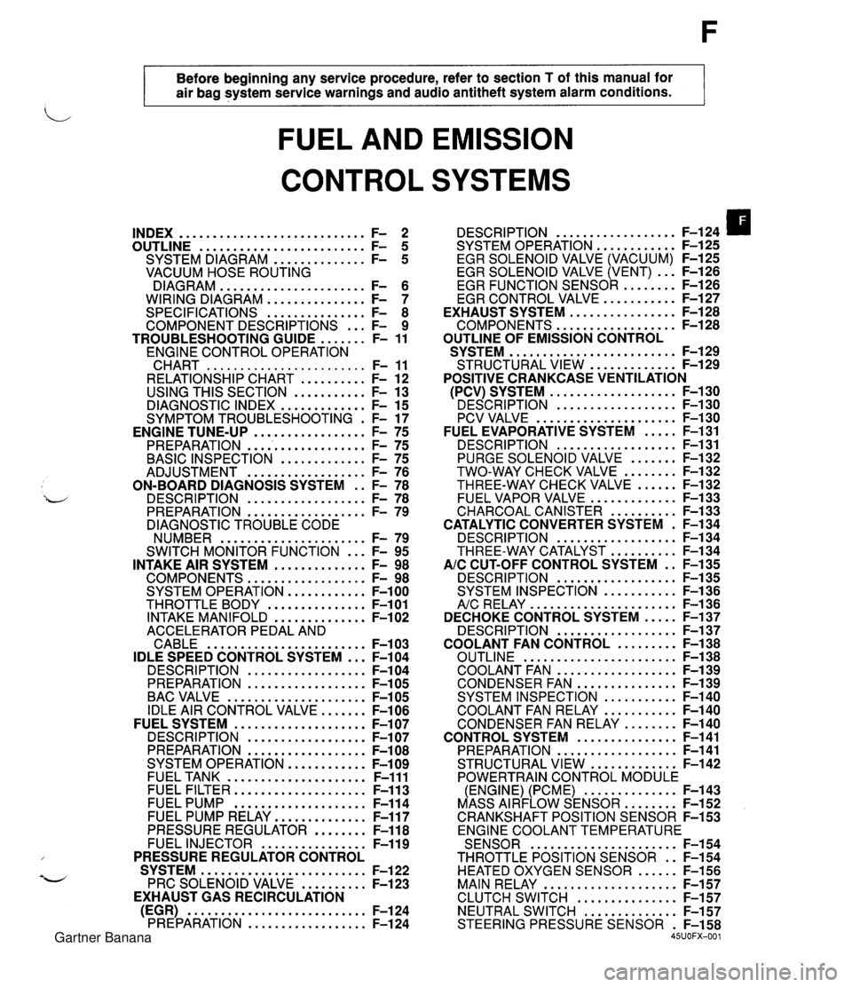
Before beginning any service procedure. refer to section T of this manual for air bag system service warnings and audio antitheft system alarm conditions . FUEL AND EMISSION CONTROL SYSTEMS INDEX ............................ F- 2 ......................... OUTLINE F- 5 .............. SYSTEM DIAGRAM F- 5 VACUUM HOSE ROUTING DIAGRAM ...................... F- 6 WIRING DIAGRAM ............... F- 7 SPECIFICATIONS ............... F- 8 COMPONENT DESCRIPTIONS ... F- 9 ....... TROUBLESHOOTING GUIDE F- 11 ENGINE CONTROL OPERATION CHART ........................ F- 11 RELATIONSHIP CHART .......... F- 12 USING THIS SECTION ........... F- 13 DIAGNOSTIC INDEX ............. F- 15 SYMPTOM TROUBLESHOOTING . F- 17 PREPARATION ................... F- 75 ............. BASIC INSPECTION F- 75 .................. ADJUSTMENT F- 76 ON-BOARD DIAGNOSIS SYSTEM . . F- 78 DESCRIPTION .................. F- 78 PREPARATION .................. F- 79 DIAGNOSTIC TROUBLE CODE NUMBER ...................... F- 79 ... SWITCH MONITOR FUNCTION F- 95 INTAKE AIR SYSTEM .............. F- 98 COMPONENTS .................. F- 98 SYSTEM OPERATION ............ F-100 THROTTLE BODY ............... F-101 INTAKE MANIFOLD .............. F-102 ACCELERATOR PEDAL AND CABLE ........................ F-103 IDLE SPEED CONTROL SYSTEM ... F-104 DESCRI PTlON .................. F-104 PREPARATION .................. F-105 BAC VALVE ..................... F-105 IDLE AIR CONTROL VALVE ....... F-106 FUEL SYSTEM .................... F-107 DESCRIPTION .................. F-107 PREPARATION .................. F-108 SYSTEM OPERATION ............ F-109 FUEL TANK ..................... F-111 FUEL FILTER .................... F-113 FUEL PUMP .................... F-114 FUEL PUMP RELAY .............. F-117 PRESSURE REGULATOR ........ F-118 FUEL INJECTOR ................ F-119 PRESSURE REGULATOR CONTROL SYSTEM ......................... F-122 PRC SOLENOID VALVE .......... F-123 EXHAUST GAS RECIRCULATION (EGR) ........................... F-124 PREPARATION .................. F-124 .................. DESCRIPTION F-124 SYSTEM OPERATION F-125 ............ EGR SOLENOID VALVE (VACUUM) F-125 EGR SOLENOID VALVE (VENT) ... F-126 ......... EGR FUNCTION SENSOR F-126 ........... EGR CONTROL VALVE F-127 ................ EXHAUST SYSTEM F-128 .................. COMPONENTS F-128 OUTLINE OF EMISSION CONTROL ......................... SYSTEM F-129 ............. STRUCTURAL VIEW F-129 POSITIVE CRANKCASE VENTILATION ................... (PCV) SYSTEM F-130 ' DESCRIPTION .................. F-I ..................... PCV VALVE F-1 ..... FUEL EVAPORATIVE SYSTEM F- .................. DESCRIPTION F- ....... PURGE SOLENOID VALVE F- ........ TWO-WAY CHECK VALVE F- ...... THREE-WAY CHECK VALVE F- ............. FUEL VAPOR VALVE F- .......... CHARCOAL CANISTER F- CATALYTIC CONVERTER SYSTEM . F- .................. DESCRIPTION F- .......... THREE-WAY CATALYST F- AIC CUT-OFF CONTROL SYSTEM . . F- .................. DESCRIPTION F- ........... SYSTEM INSPECTION F- ...................... A/c RELAY F-1 36 ..... DECHOKE CONTROL SYSTEM F-137 .................. DESCRIPTION F-137 ......... COOLANT FAN CONTROL F-138 ....................... OUTLINE F-138 .................. COOLANT FAN F-139 ............... CONDENSER FAN F-139 ........... SYSTEM INSPECTION F-140 ........... COOLANT FAN RELAY F-140 ........ CONDENSER FAN RELAY F-140 ............... CONTROL SYSTEM F-141 .................. PREPARATION F-141 ............. STRUCTURAL VIEW F-142 POWERTRAIN CONTROL MODULE .............. (ENGINE) (PCME) F-143 ........ MASS AIRFLOW SENSOR F-152 CRANKSHAFT POSITION SENSOR F-153 ENGINE COOLANT TEMPERATURE ...................... SENSOR F-154 THROTTLE POSITION SENSOR . . F-154 HEATED OXYGEN SENSOR ...... F-156 MAIN RELAY .................... F-157 ............... CLUTCH SWITCH F-157 NEUTRAL SWITCH .............. F-157 STEERING PRESSURE SENSOR . F-158 45UOFX-001 Gartner Banana
Page 152 of 1708
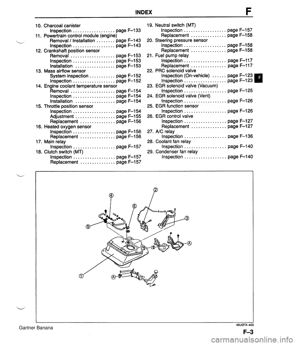
INDEX 10. Charcoal canister lnspection . . . . . . . . . . . . . . . . . . page F-133 11. Powertrain control module (engine) Removal / Installation . . . . . . . . page F-143 lnspection . . . . . . . . . . . . . . . . . . page F-143 12. Crankshaft position sensor Removal . . . . . . . . . . . . . . . . . . . page F-153 lnspection . . . . . . . . . . . . . . . . . . page F-153 lnstallation . . . . . . . . . . . . . . . . . page F-153 13. Mass airflow sensor System inspection . . . . . . . . . . . page F-152 lnspection . . . . . . . . . . . . . . . . . . page F-152 14. Engine coolant temperature sensor Removal . . . . . . . . . . . . . . . . . . . page F-154 lnspection . . . . . . . . . . . . . . . . . . page F-154 Installation . . . . . . . . . . . . . . . . . page F-154 15. Throttle position sensor lnspection . . . . . . . . . . . . . . . . . . page F-154 Adjustment . . . . . . . . . . . . . . . . . page F-155 Replacement . . . . . . . . . . . . . . . page F-156 16. Heated oxygen sensor lnspection . . . . . . . . . . . . . . . . . . page F-156 Replacement . . . . . . . . . . . . . . . page F-156 17. Main relay lnspection . . . . . . . . . . . . . . . . . . page F-157 18. Clutch switch (MT) lnspection . . . . . . . . . . . . . . . . . . page F-157 Replacement . . . . . . . . . . . . . . . page F-157 19. Neutral switch (MT) lnspection . . . . . . . . . . . . . . . . . . page F-157 Replacement . . . . . . . . . . . . . . . page F-158 20. Steering pressure sensor lnspection . . . . . . . . . . . . . . . . . . page F-158 Replacement . . . . . . . . . . . . . . . page F-158 21. Fuel pump relay lnspection . . . . . . . . . . . . . . . . . . page F-117 Replacement . . . . . . . . . . . . . . . page F-117 22. PRC solenoid valve lnspection (On-vehicle) . . . . . . page F-123 lnspection . . . . . . . . . . . . . . . . . . page F-123 23. EGR solenoid valve (Vacuum) lnspection . . . . . . . . . . . . . . . . . . page F-125 24. EGR solenoid valve (Vent) lnspection . . . . . . . . . . . . . . . . . . page F-126 25. EGR function sensor lnspection . . . . . . . . . . . . . . . . . . page F-126 26. EGR control valve lnspection . . . . . . . . . . . . . . . . . . page F-127 Replacement . . . . . . . . . . . . . . . page F-127 27. NC relay lnspection . . . . . . . . . . . . . . . . . . page F-136 28. Coolant fan relay lnspection . . . . . . . . . . . . . . . . . . page F-140 29. Condenser fan relay lnspection . . . . . . . . . . . . . . . . . . page F-140 Gartner Banana
Page 159 of 1708
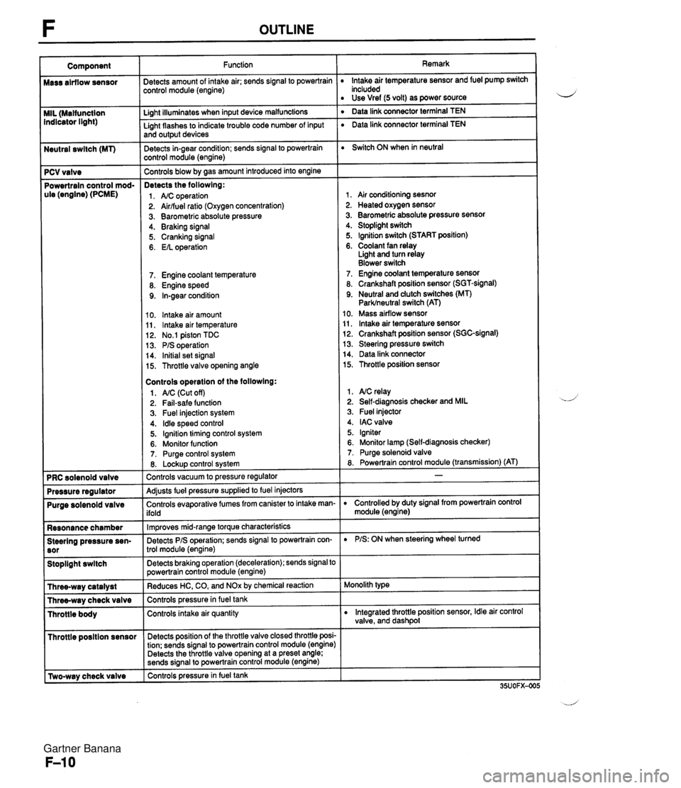
Neutral swltch (MT) 7 PCV valve Powertrain control mod- ule (engine) (PCME) Purge solenoid valve Resonance chamber Steering pressure sen- Stoplight swltch I Throttle posltion sensor r [Two-way check valve Function jetects amount of intake air; sends signal to powertrain :ontrol module (engine) Li~ht illuminates when input device malfunctions - Light flashes to indicate trouble code number of input and output devices Detects in-gear condition; sends signal to powertrain :ontrol module (engine) - Controls blow by aas amount introduced into engine Detects the followlng: 1. A/C operation 2. Airlfuel ratio (Oxygen concentration) 3. Barometric absolute pressure 4. Braking signal 5. Cranking signal 6. EIL operation 7. Engine coolant temperature 8. Engine speed 9. In-gear condition 10. lntake air amount 11, lntake air temperature 12. No.1 piston TDC 13. PIS operation 14. Initial set signal 15. Throttle valve opening angle Controls operatlon of the followlng: 1. AIC (Cut off) 2. Fail-safe function 3. Fuel injection system 4. ldle speed control 5. Ignition timing control system 6. Monitor function 7. Purge control system 8. Lockup control svstem Controls vacuum to pressure regulator -- Adjusts fuel pressure supplied to fuel injectors Controls evaporative fumes from canister to intake man- ifold -- lm~roves mid-ranae torque characteristics -. Detects PIS operation; sends signal to powertrain con- trol module (engine) -- Detects braking operation (deceleration); sends signal to powertrain control module (engine) Reduces HC, CO, and NOx by chemical reaction Controls pressurein fuel tank Controls intake air quantity Detects position of the throttle valve closed throttle posi- tion; sends signal to powertrain control module (engine) Detects the throttle valve opening at a preset angle; sends si~nal to powertrain control module (engine) controls pressure in fuel tank Remark lntake air temperature sensor and fuel pump switch included Use Vref (5 volt) as power source ' Data link connector terminal TEN ' Data link connector terminal TEN Switch ON when in neutral 1, Air conditioning sesnor 2. Heated oxygen sensor 3. Barometric absolute pressure sensor 4. Stoplight switch 5. Ignition switch (START position) 6. Coolant fan relay Light and turn relay Blower switch 7. Engine coolant temperature sensor 8. Crankshaft position sensor (SGT-signal) 9. Neutral and dutch switches (MT) Parklneutral switch (AT) 10. Mass airflow sensor 11, lntake air temperature sensor 12. Crankshaft position sensor (SGC-signal) 13. Steering pressure switch 14. Data link connector 15. Throttle position sensor 1. NC relay 2. Self-diagnosis checker and MIL 3. Fuel injector 4. IAC valve 5. Igniter 6. Monitor lamp (Self-diagnosis checker) 7. Purge solenoid valve 8. Powertrain control module (transmission) (AT) D Controlled by duty signal from powertrain control module (engine) D PIS: ON when steering wheel turned Monolith type D Integrated throttle position sensor, Idle air control valve, and dashpol Gartner Banana
Page 291 of 1708

CONTROL SYSTEM STRUCTURAL VIEW i 1. Powertrain control module (engine) 6. Heated oxygen sensor Inspection . . . . . . . . . . . . . . . . . . page F-144 Inspection . . . . . . . . . . . . . . . . . . page F-156 Removal / Installation . . . . . . . . page F-143 Replacement . . . . . . . . . . . . . . . page F-156 2. Crankshaft position sensor 7. Main relay Removal . . . . . . . . . . . . . . . . . . . page F-153 Inspection . . . . . . . . . . . . . . . . . . page F-156 lnspection . . . . . . . . . . . . . . . . . . page F-153 8. Clutch switch Installation . . . . . . . . . . . . . . . . . page F-153 Inspection . . . . . . . . . . . . . . . . . . page F-157 3. Mass airflow sensor Replacement . . . . . . . . . . . . . . . page F-157 System inspection . . . . . . . . . . . page F-152 9. Neutral switch Inspection . . . . . . . . . . . . . . . . . . page F-152 Inspection . , . . . . . . . . . . . . . . . . page F-157 4. Engine coolant temperature sensor Replacement . . . . . . . . . . . . . . . page F-157 Removal . . . . . . . . . . . . . . . . . . . page F-154 10. Steering pressure sensor Inspection . . . . . . . . . . . . . . . . . . page F-154 Inspection . . . . . . . . . . . . . . . . . . page F-158 Installation . . . , . . . . . . . . . . . . . page F-154 Replacement . . . . . . . . . . . . . . . page F-158 5. Throttle position sensor -,' Inspection . . . . . . . . . . . . . . . . . . page F-155 Adjustment . . . . . . . . . . . . . . . . . page F-155 Replacement . . . . . . . . . . . . . . . page F-156 Gartner Banana
Page 294 of 1708
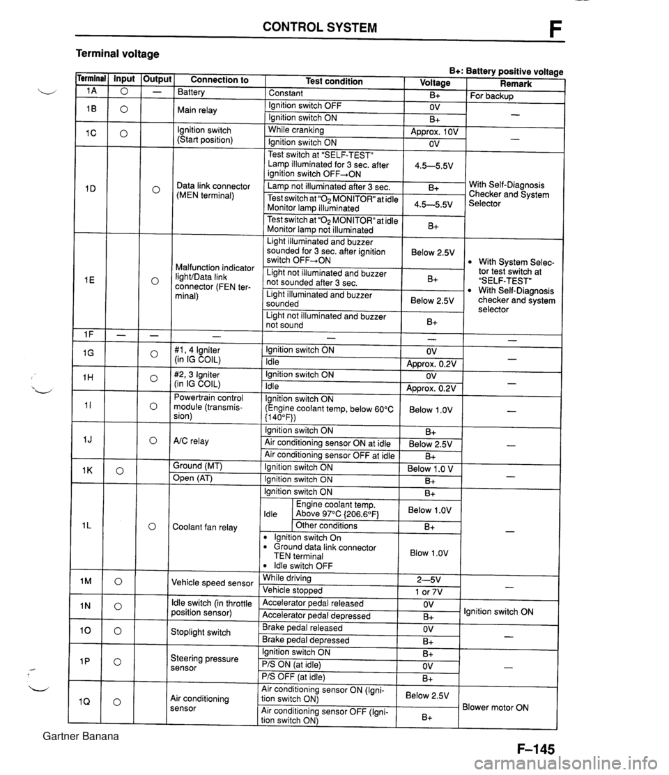
CONTROL SYSTEM F Terminal voltage B+: Battery positive voltage Test condition I Voltage I Remark - - - - - - - - - - - - - - - - - - Connection to Battery Constant Ignition switch OFF Main relay - B+ OV lgnition switch (Start position) For backup - Ignition switch ON While cranking Lamp illuminated for 3 sec. after 1 4.5-5.5V ianition switch OFF+ON 1 B+ Approx. 1 OV Ignition switch ON - - OV Data link connector (MEN terminal) Test switch at "SELF-TEST" .. Lamp not illuminated after 3 sec. Test switch at "02 MONITOR" at idle Monitor lam illuminated & 4.5-5.5v . . I Malfunction indicator IighVData link connector (FEN ter- minal) With Self-Diagnosis Checker and System Selector Test switch at "02 MONITOR" at idle Monitor lamp not illuminated Light illuminated and buzzer sounded for 3 sec. after ignition switch OFF-ON B+ tor tesiswitch at "SELF-TEST" With Self-Diagnosis checker and system selector Below 2.5V 1 Light illuminated and buzzer sounded 1 Below 2.5V I With System Selec- Light not illuminated and buzzer not sounded after 3 sec. I Light not illuminated and buzzer 1 n. 1 B+ not sound I D+ 1 - #I, 4 lgniter (in IG COIL) #2,3 Igniter (in IG COIL) Powertrain control module (transmis- sion) - Ignition switch ON Idle Ignition switch ON Idle lgnition switch ON (Engine coolant temp, below 60°C {I 40°F)) Ignition switch ON AtC relay Air conditioning sensor ON at idle Air conditioning sensor OFF at idle Ground (MT) - OV Approx. 0.2V OV Approx. 0.2V Below 1 .OV B+ Below 2.5V B+ - - - - , * Open (AT) - Ignition switch ON ( Below 1 .O V I Engine coolant temp. I Below .OV I ldle Above 97°C (206.6OF1 Ignition switch ON I I B+ Ignition switch ON Coolant fan relay B+ . - Other conditions lgnition switch On dround data link connector TEN terminal I Blow 1.0" I B+ Vehicle speed sensor ldle switch OFF While driving Vehicle sto~wed ldle switch (in throttle position sensor) 2-5V 1 or 7V . , Accelerator pedal released Accelerator ~edal de~ressed - Stoplight switch OV B+ Brake pedal released Brake ~edal deoressed lgnition switch ON Steering pressure sensor OV B+ I I - Ignition switch ON B+ - PIS ON (at idle) PIS OFF (at idle) Air conditioning sensor Air conditioning sensor ON (Igni- tion switch ON) Air conditioning sensor OFF (Igni- tion switch ON) OV B+ - Below 2.5V B+ Blower motor ON Gartner Banana
Page 628 of 1708

Before beginning any service procedure. refer to section T of this manual for I air bag system service warnings and audio antitheft system alarm conditions . STEERING SYSTEM INDEX ....................................... N- 2 OUTLINE ..................................... N- 4 SPECIFICATIONS ........................... N- 4 MANUAL STEERING .......................... N- 4 PREPARATION ............................. N- 4 ................ TROUBLESHOOTING GUIDE N- 5 BOOT ...................................... N- 6 STEERING WHEEL AND COLUMN ........... N- 8 ............. STEERING GEAR AND LINKAGE N-12 ENGINE SPEED SENSING POWER STEERING .......................... N-18 PREPARATION ............................. N-18 TROUBLESHOOTING GUIDE ................ N-20 AIR BLEEDING ............................. N-21 POWER STEERING FLUID ................... N-22 STEERING WHEEL AND COLUMN ........... N-24 STEERING GEAR AND LINKAGE ............. N-25 POWER STEERING OIL PUMP ............... N-33 DRIVE BELT ................................ N-37 25UONX-001 Gartner Banana
Page 630 of 1708
![MAZDA MX-5 1994 Workshop Manual INDEX POWER STEERING STEERING WHEEL PLAY: [ 0-30mm (0-1.18 in) ] / DRIVE BELT DEFLECTION I= I LIMIT: 11.5mm (0.45 in) at 98 N (1 0 kgf, 22 Ibf) I =!IS 1. Boot Replacement ................ page N- 6 MAZDA MX-5 1994 Workshop Manual INDEX POWER STEERING STEERING WHEEL PLAY: [ 0-30mm (0-1.18 in) ] / DRIVE BELT DEFLECTION I= I LIMIT: 11.5mm (0.45 in) at 98 N (1 0 kgf, 22 Ibf) I =!IS 1. Boot Replacement ................ page N- 6](/img/28/57072/w960_57072-629.png)
INDEX POWER STEERING STEERING WHEEL PLAY: [ 0-30mm (0-1.18 in) ] / DRIVE BELT DEFLECTION I=' I LIMIT: 11.5mm (0.45 in) at 98 N (1 0 kgf, 22 Ibf) 'I =!IS 1. Boot Replacement ................ page N- 6 2. Steering wheel. and column .... On-vehicle inspection pages N- 8,24 Removal / ................... page N- 9 Disassembly / Inspection 1 Assembly .................. page N-10 3. Steering gear and linkage Removal I Installation ......... page N-25 Air bleeding ................. page N-21 Disassembly I Inspection / Assembly .................. page N-26 4. Power steering oil pump ......... Removal / Installation page N-33 ................. Air bleeding page N-21 .......... Power steering fluid page N-22 5. Drive belt ................... Inspection page N-37 .................. Adjustment page N-38 ................ Replacement page N-38 Gartner Banana