turn signal MAZDA MX-5 1994 Workshop Manual
[x] Cancel search | Manufacturer: MAZDA, Model Year: 1994, Model line: MX-5, Model: MAZDA MX-5 1994Pages: 1708, PDF Size: 82.34 MB
Page 9 of 1708

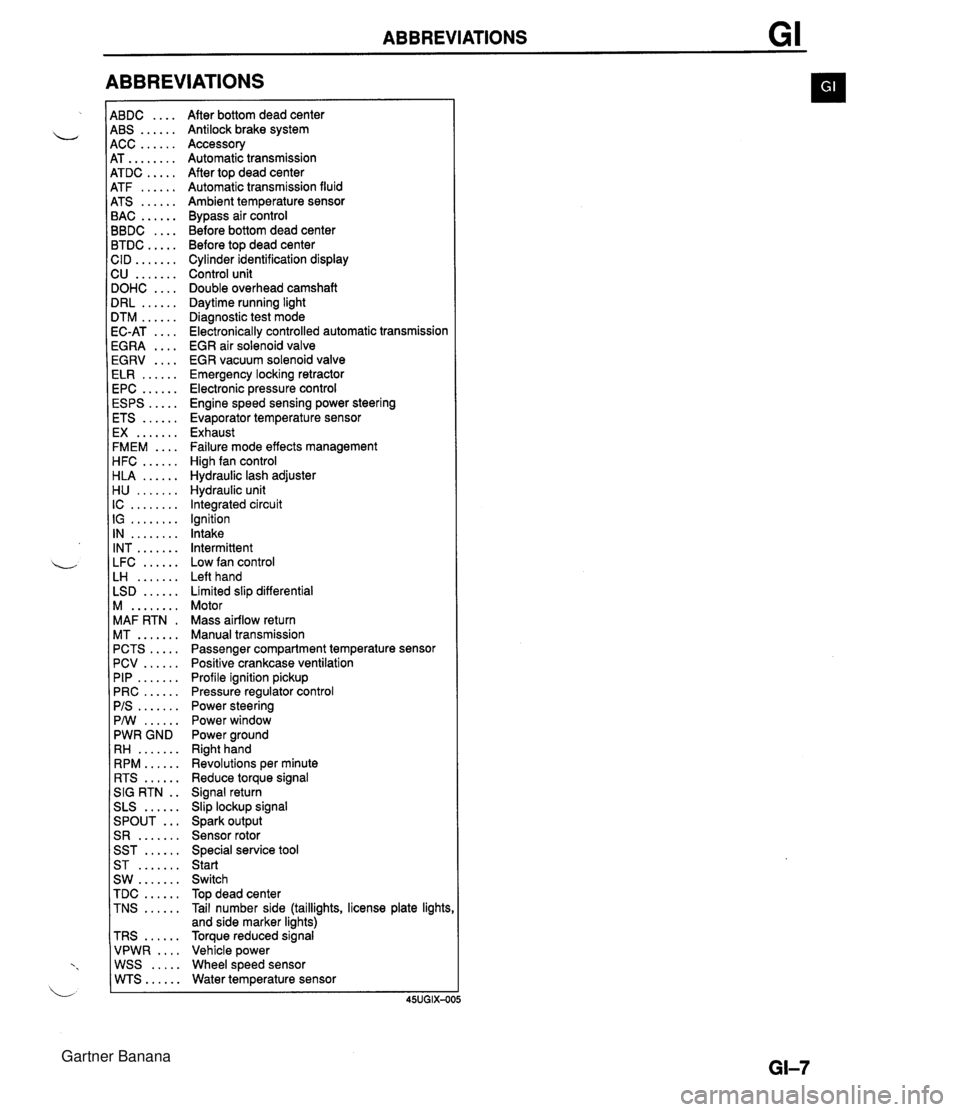
ABBREVIATIONS 4BDC .... 4BS ...... 4CC ...... 4T ........ 4TDC ..... 4TF ...... 4TS ...... 3AC ...... 3BDC .... 3TDC ..... :ID ....... 2U ....... IOHC .... IRL ...... ITM ...... IC-AT .... iGRA .... EGRV .... ELR ...... EPC ...... ESPS ..... ETS ...... EX ....... FMEM .... HFC ...... HLA ...... H U ....... IC ........ IG ........ IN ........ INT ....... LFC ...... LH ....... LSD ...... M ........ MAF RTN . MT ....... PCTS ..... PCV ...... PIP ....... PRC ...... PIS ....... PMI ...... PWR GND RH ....... RPM ...... RTS ...... SIG RTN . . SLS ...... ... SPOUT S R ....... SST ...... ST ....... SW ....... TDC ...... TNS ...... TRS ...... VPWR .... WSS ..... WTS...... After bottom dead center Antilock brake system Accessory Automatic transmission After top dead center Automatic transmission fluid Ambient temperature sensor Bypass air control Before bottom dead center Before top dead center Cylinder identification display Control unit Double overhead camshaft Daytime running light Diagnostic test mode Electronically controlled automatic transmission EGR air solenoid valve EGR vacuum solenoid valve Emergency locking retractor Electronic pressure control Engine speed sensing power steering Evaporator temperature sensor Exhaust Failure mode effects management High fan control Hydraulic lash adjuster Hydraulic unit Integrated circuit Ignition Intake Intermittent Low fan control Left hand Limited slip differential Motor Mass airflow return Manual transmission Passenger compartment temperature sensor Positive crankcase ventilation Profile ignition pickup Pressure regulator control Power steering Power window Power ground Right hand Revolutions per minute Reduce torque signal Signal return Slip lockup signal Spark output Sensor rotor Special service tool Start Switch Top dead center Tail number side (taillights, license plate lights and side marker lights) Torque reduced signal Vehicle power Wheel speed sensor Water temperature sensor Gartner Banana
Page 159 of 1708

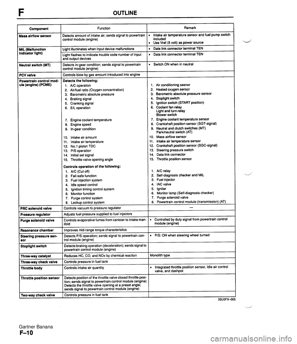
Neutral swltch (MT) 7 PCV valve Powertrain control mod- ule (engine) (PCME) Purge solenoid valve Resonance chamber Steering pressure sen- Stoplight swltch I Throttle posltion sensor r [Two-way check valve Function jetects amount of intake air; sends signal to powertrain :ontrol module (engine) Li~ht illuminates when input device malfunctions - Light flashes to indicate trouble code number of input and output devices Detects in-gear condition; sends signal to powertrain :ontrol module (engine) - Controls blow by aas amount introduced into engine Detects the followlng: 1. A/C operation 2. Airlfuel ratio (Oxygen concentration) 3. Barometric absolute pressure 4. Braking signal 5. Cranking signal 6. EIL operation 7. Engine coolant temperature 8. Engine speed 9. In-gear condition 10. lntake air amount 11, lntake air temperature 12. No.1 piston TDC 13. PIS operation 14. Initial set signal 15. Throttle valve opening angle Controls operatlon of the followlng: 1. AIC (Cut off) 2. Fail-safe function 3. Fuel injection system 4. ldle speed control 5. Ignition timing control system 6. Monitor function 7. Purge control system 8. Lockup control svstem Controls vacuum to pressure regulator -- Adjusts fuel pressure supplied to fuel injectors Controls evaporative fumes from canister to intake man- ifold -- lm~roves mid-ranae torque characteristics -. Detects PIS operation; sends signal to powertrain con- trol module (engine) -- Detects braking operation (deceleration); sends signal to powertrain control module (engine) Reduces HC, CO, and NOx by chemical reaction Controls pressurein fuel tank Controls intake air quantity Detects position of the throttle valve closed throttle posi- tion; sends signal to powertrain control module (engine) Detects the throttle valve opening at a preset angle; sends si~nal to powertrain control module (engine) controls pressure in fuel tank Remark lntake air temperature sensor and fuel pump switch included Use Vref (5 volt) as power source ' Data link connector terminal TEN ' Data link connector terminal TEN Switch ON when in neutral 1, Air conditioning sesnor 2. Heated oxygen sensor 3. Barometric absolute pressure sensor 4. Stoplight switch 5. Ignition switch (START position) 6. Coolant fan relay Light and turn relay Blower switch 7. Engine coolant temperature sensor 8. Crankshaft position sensor (SGT-signal) 9. Neutral and dutch switches (MT) Parklneutral switch (AT) 10. Mass airflow sensor 11, lntake air temperature sensor 12. Crankshaft position sensor (SGC-signal) 13. Steering pressure switch 14. Data link connector 15. Throttle position sensor 1. NC relay 2. Self-diagnosis checker and MIL 3. Fuel injector 4. IAC valve 5. Igniter 6. Monitor lamp (Self-diagnosis checker) 7. Purge solenoid valve 8. Powertrain control module (transmission) (AT) D Controlled by duty signal from powertrain control module (engine) D PIS: ON when steering wheel turned Monolith type D Integrated throttle position sensor, Idle air control valve, and dashpol Gartner Banana
Page 227 of 1708

ON-BOARD DIAGNOSIS SYSTEM ON-BOARD DIAGNOSIS SYSTEM DESCRIPTION When troubles occur in the main input devices or output devices, check for the cause using the SST. Q Failures of each input and output device are indicated and retrieved from the powertrain control module (engine) as diagnosis trouble code numbers. Note For input devices, the PCME continuously checks for malfunctions. For output devices, it checks for malfunctions only in a three-second period after the ignition switch is turned to ON, or the TEN termi- nal of the data link connector is grounded. - INPUT SIGNALS POWERTRAIN CONTROL MODULE (ENGINE) I- -t INPUT DEVICES FAIL-SAFE FUNCTION . ON-BOARD ,, DIAGNOSIS -+ SYSTEM - - 1 I I MALFUNCTIQN DISPLAY FUNCTION -t b P v C-- MONITOR FUNCTION u SYSTEM SELF-DIAGNOSIS SELECTOR CHECKER I CHECK Gartner Banana
Page 302 of 1708

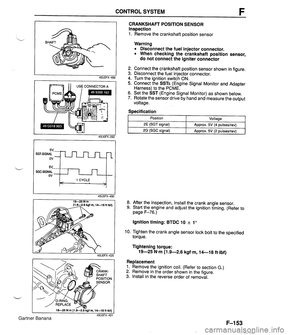
CONTROL SYSTEM 1 1 USE CONNECTOR A CRANKSHAFT POSITION SENSOR Inspection 1. Remove the crankshaft position sensor 5v- - - - SGGSIGNAL ov Warning Disconnect the fuel injector connector. When checking the crankshaft position sensor, do not connect the igniter connector - - - - I 1 CYCLE < > 2. Connect the crankshaft position sensor shown in figure. 3. Disconnect the fuel injector connector. 4. Turn the ignition switch ON. 5. Connect the SSTs (Engine Signal Monitor and Adapter Harness) to the PCME. 6. Set the SST (Engine Signal Monitor) as shown below. 7. Rotate the sensor drive by hand and measure the output voltage. Specification I 1 - Position - ~oltaael 8. After the inspection, install the crank angle sensor. 9. Start the engine and adjust the ignition timing. (Refer to page F-76.) 2E (SGT signal) 2G (SGC signal) Ignition timing: BTDC 10 2 1" Approx. 5V (4 pulseslrev) Approx. 5V (2 pulseslrev) 10. Tighten the crank angle sensor lock bolt to the specified torque. Tightening torque: 19-25 N-m (1 .+2.6 kgfem, 14-1 8 ftelbf} Replacement 1. Remove the ignition coil. (Refer to section G.) 2. Remove in the order shown in the figure. 3. Install in the reverse order of removal. Gartner Banana
Page 304 of 1708

CONTROL SYSTEM DCB IIIf I 1 USECONNECTORA I Variable resister 1. Remove the PCME. (Refer to page F-143.) 2. Connect the SSTs (Engine Signal Monitor and Adapt- er Harness) to the PCME. 3. Set the SST (Engine Signal Monitor) to position 2M. 4. Turn the ignition switch ON. 5. Rotate the throttle link by hand and verify that voltage is within the specification. Specification 6. If not as specified, adjust the throttle position sensor. (Refer to below.) - PCME terminal Adjustment Throttle valve position I Wide open throttle ~osition Note The throttle adjusting screw is set at the factory and must not be adjusted. Any adjustment will negatively effect the engine per- formance. Idle switch 1. Turn the ignition switch OFF and the throttle valve closed throttle position. 2. Disconnect the throttle position sensor connector. 3. Loosen the throttle position sensor screws. 4. Rotate the throttle position sensor and adjust continuity of the sensor terminals C and D as shown. Specification I Clearance Continuity I 5. Tighten the throttle position sensor screws. 0.3 mm (0.012 in} Tightening torque: 1.6-2.3 N.m (16-24 kgf-m, 14--20 in-lbf) Yes Variable resister 1. Remove the PCME. (Refer to page F-143.) 2. Connect the SSTs to the PCME connector as shown. 3. Verify that the throttle valve is fully closed. 4. Loosen the attaching screws. 5. Turn the ignition switch to ON. 6. Measure the PCME terminal 2M voltage. 7. Adjust the voltage to the specification 0.4 mm (0.01 6 in) I No Gartner Banana
Page 439 of 1708

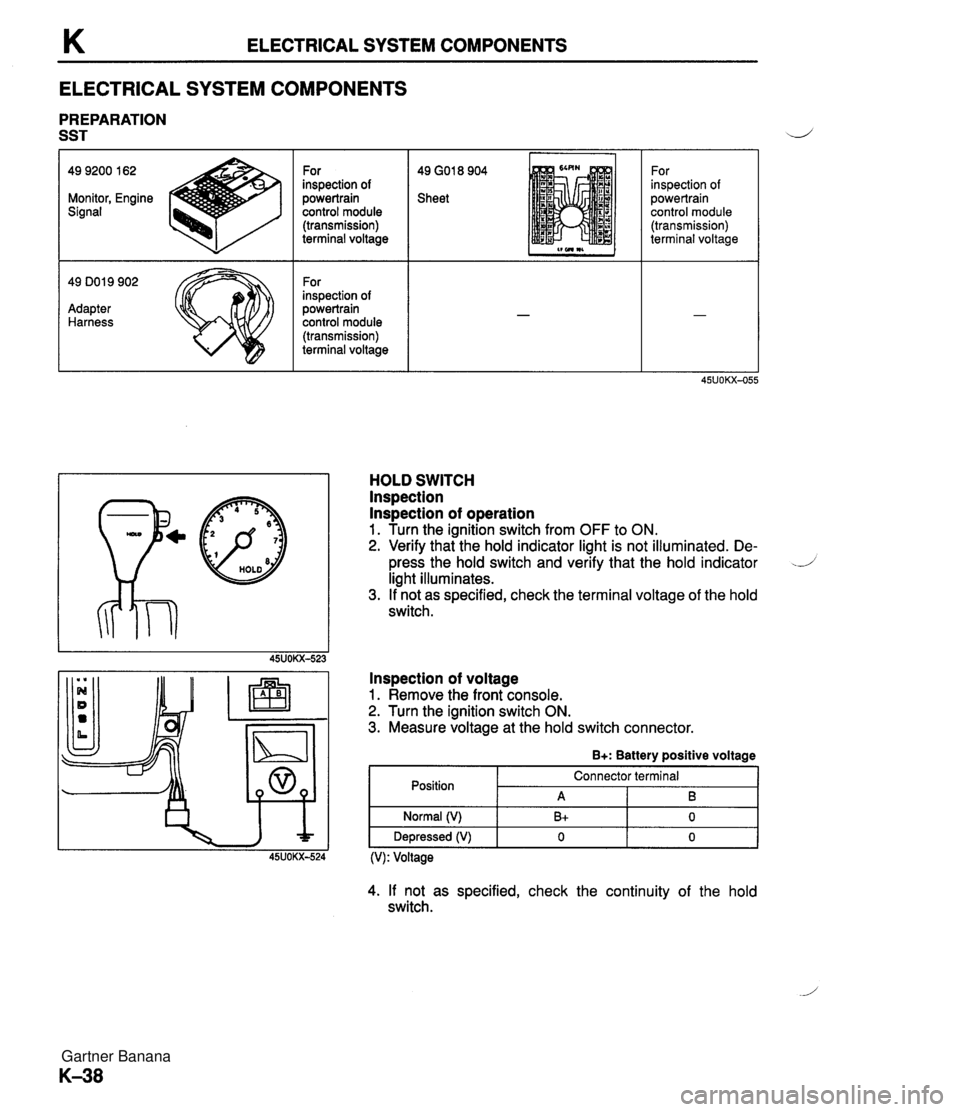
K ELECTRICAL SYSTEM COMPONENTS ELECTRICAL SYSTEM COMPONENTS PREPARATION SST 49 GO1 8 904 Sheet 49 9200 162 Monitor, Engine Signal - 49 DO1 9 902 Adapter Harness For inspection of powertrain control module (transmission) terminal voltage For inspection of powertrain control module (transmission) terminal voltage p@ HOLD For inspection of powertrain control module (transmission) terminal voltage HOLD SWITCH lnspection lnspection of operation 1. Turn the ignition switch from OFF to ON. 2. Verify that the hold indicator light is not illuminated. De- press the hold switch and verify that the hold indicator -J light illuminates. 3. If not as specified, check the terminal voltage of the hold switch. lnspection of voltage 1. Remove the front console. 2. Turn the ignition switch ON. 3. Measure voltage at the hold switch connector. B+: Battery positive voltage Position (V): Voltage Normal (V) Depressed (V) 4. If not as specified, check the continuity of the hold switch. Connector terminal A B+ 0 B 0 0 Gartner Banana
Page 444 of 1708

ELECTRICAL SYSTEM COMPONENTS K I POWERTRAIN CONTROL POWERTRAIN CONTROL MODULE (TRANSMISSION) lns~ection 1. kemove the powertrain control module (Transmission). (Refer to page K-45.) 2. Disconnect the control module connectors. 3. Connect the SSTs (Engine Signal Monitor and Adapt- er Harness) to the powertrain control module (Transmis- sion) as shown. 4. Place the SST (sheet) on the Engine Signal Monitor. 5. Turn the ignition switch ON. 6. Measure the terminal voltage at each terminal. 7. If any control module terminal voltage is incorrect, check the related input of output devices and wiring. If no prob- lem is found, replace the powertrain control module (Transmission). Caution Applying voltage to terminals A and B of this SST will damage the SST. Gartner Banana
Page 853 of 1708

T OUTLINE OUTLINE TROUBLESHOOTING GUIDE Symptom a Speedometer does not operate or indication is incorrect a Tachometer does not operate Water temperature gauge does not operate Fuel gauge does not operate a Oil pressure gauge does not operate a Brake system warning light remains illuminated Brake system warning light does not illuminate when parking brake on a Brake system warning light does not illuminate when brake fluid in reservoir is below MIN a OID off indicator light does not illuminate when OID off switch turned on Seat belt warning light remains on six seconds after ignition switch is turned on (Timer function does not operate) Seat belt warning light does not illuminate when ignition switch is first turned on a Headlights do not illuminate Headlight does not illuminate (Right or left) Retractable headlight actuator do not operate (Both sides) Retractable headlight actuator does not operate (One side) Stoplights do not illuminate (All) Stoplight does not illuminate (One only) Turn and hazard warning functions do not operate Turn signals not operate (Hazard warning function operates normally) Hazard warning function does not operate (Turn signals function normally) Back-up lights does not illuminate Taillights, side marker lights, and license plate lights do not illuminate Daytime running lights do not illuminate Daytime running light function does not cancel lnterior lights do not illuminate Interior liahts remains illuminated (Control switch: DOOR ~osition) Horn does not sound Vehicle speed cannot be set (Cruise control unit will not hold vehicle speed) Speakers do not operate (Without headrest speakers) Speakers do not operate (With headrest speakers) Poor sound quality or noise (Radio) Poor sound quality (Cassette tape player) Cassette tape will not load Cassette tape will not play Compact disc will not load Compact disc skips No sound can be heard Some speakers do not operate Bodysonic will not play Service code table (With passenger-side air bag) Service code table (With out ~assenaer-side air baa) Reference page T-24 T-25 T-26 T-27 T-28 T-36 T-37 T-37 Gartner Banana
Page 856 of 1708

FUSE SPECIFICATIONS Main Fuse Block u I Fuse Amperes Protected circuit HEAD INJ MAIN BTN 30A 30A COOLING FAN (AD FAN) 1 ABS I 60A I Antilock brake svstem I Headlight relay, Headlight switch Alternator, Diagnostic module (for air bag system) 80A 40A ST SIG RETRACTOR Fuse Box No.1 Except circuits protected in main fuse block: INJ 30A, HEAD 30A, RETRACTOR 30A TNS relay, Headlight switch 30A 20A EGI main relay, Coolant fan relay A/C relay 10A 30A Park l Neutral switch, Circuit-opening relay Retractable headlight actuator Fuse ENGINE METER (POWER WIND) Amperes 15A WIPER TAIL ROOM I 10A I PCME, Key reminder switch, Audio unit I Protected circuit EGI main relay, Coolant fan relay 15A 30A STOP HAZARD CIGAR 15A I Cigarette lighter, Audio unit 1 Instrument cluster, Turn signal switch, Timer and buzzer unit, Cruise control main switch Power window switch 20A 15A Fuse Box No.2 Blower switch, Wiper switch Taillights, Side marker lights, License plate lights, Parking lights 15A 15A Fuse Amperes Protected circuit I Stoplight switch, Horn switch, Cruise control unit Flasher unit Fuse Color Code (DEFOG) (ANTENNA) I Fuse amperes I Color code Fuse type 25UOTX-013 20A 20A I I 10A Red 1 I Rear window defroster Power antenna Plate type 15A 20A Light blue Yellow 30A 30A 80A Light green Pink Black Cartridge type Gartner Banana
Page 858 of 1708

RELAY T RELAY STRUCTURAL VIEW 1. Headlight relay 2. TNS relay 3. Retractable headlight relay 4. EGI main relay 5. Circuit-opening relay 6. Rear window defroster timer unit 7. Coolant fan relay 8. Horn relay 9. Flasher unit 10. Rear window defroster relay DESCRIPTION The DRL control unit (Canada only) controls the operation of the turn signal lights. When the ignition switch is at ON or START, the front turn signal lights illuminate as running lights, except when one of the following switches is on: Headlight switch. Turn signal light switch. Hazard warning switch. Parking brake switch. Gartner Banana