MAZDA MX-5 1994 Workshop Manual
Manufacturer: MAZDA, Model Year: 1994, Model line: MX-5, Model: MAZDA MX-5 1994Pages: 1708, PDF Size: 82.34 MB
Page 331 of 1708
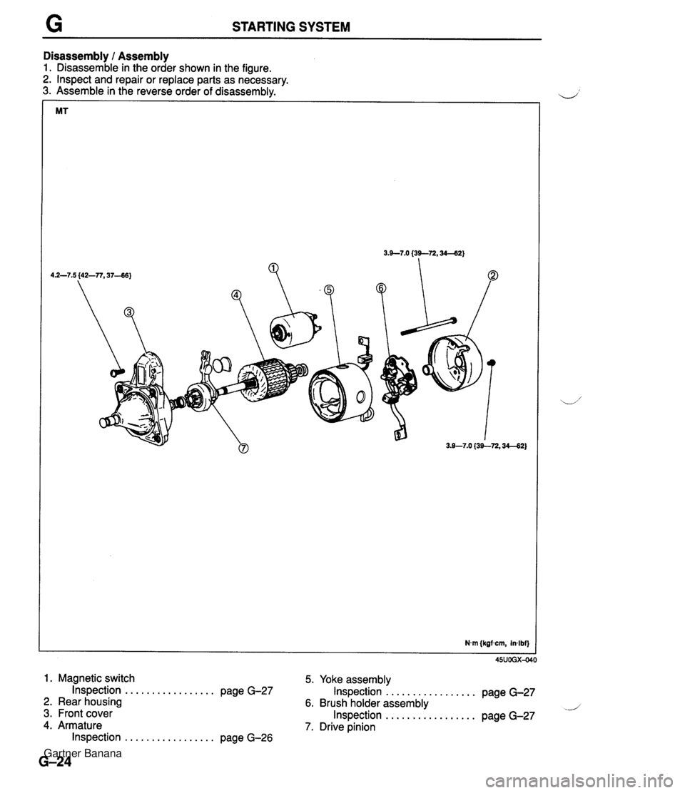
STARTING SYSTEM Disassembly / Assembly 1. Disassemble in the order shown in the figure. 2. Inspect and repair or replace parts as necessary. 3. Assemble in the reverse order of disassemblv. Nvn {kgfscm, inlbf) 1. Magnetic switch 5. Yoke assemblv Inspection ................. page G-27 Inspection ................. page G-27 2. Rear housing 6. Brush holder assembly d 3. Front cover Inspection ................. page G-27 4. Armature 7. Drive pinion Inspection ................. page G-26 Gartner Banana
Page 332 of 1708
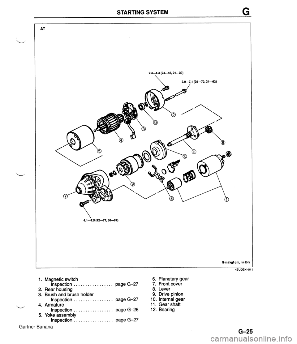
STARTING SYSTEM G 1. Magnetic switch Inspection ................. page G-27 2. Rear housing 3. Brush and brush holder ................. Inspection page G-27 4. Armature ................. Inspection page G-26 5. Yoke assembly ................. Inspection page G-27 6. Planetary gear 7. Front cover 8. Lever 9. Drive pinion 10. Internal gear 11. Gear shaft 12. Bearing Gartner Banana
Page 333 of 1708
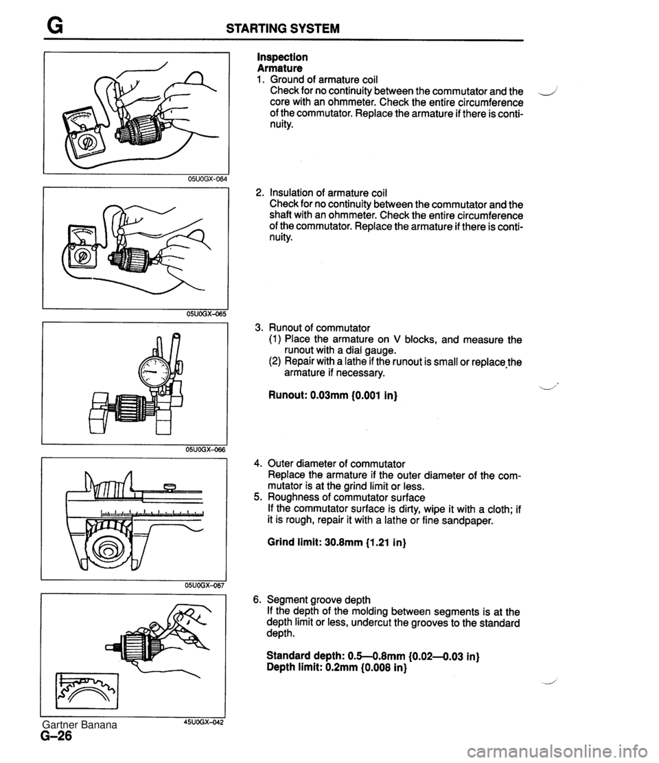
STARTING SYSTEM Inspection Armature 1. Ground of armature coil Check for no continuity between the commutator and the .J core with an ohmmeter. Check the entire circumference of the commutator. Replace the armature if there is conti- nuity. 2, Insulation of armature coil Check for no continuity between the commutator and the shaft with an ohmmeter. Check the entire circumference of the commutator. Replace the armature if there is conti- nuity. 3. Runout of commutator (1) Place the armature on V blocks, and measure the runout with a dial gauge. (2) Repair with a lathe if the runout is small or replace,the armature if necessary. -1' Runout: 0.03mm (0.001 in) 4. Outer diameter of commutator Replace the armature if the outer diameter of the com- mutator is at the grind limit or less. 5. Roughness of commutator surface If the commutator surface is dirty, wipe it with a cloth; if it is rough, repair it with a lathe or fine sandpaper. Grind limit: 30.8mm (1.21 in) 6. Segment groove depth If the depth of the molding between segments is at the depth limit or less, undercut the grooves to the standard depth. Standard depth: 0.5--0.8mm (0.02-4.03 in) Depth limit: 0.2mm (0.008 in) Gartner Banana
Page 334 of 1708
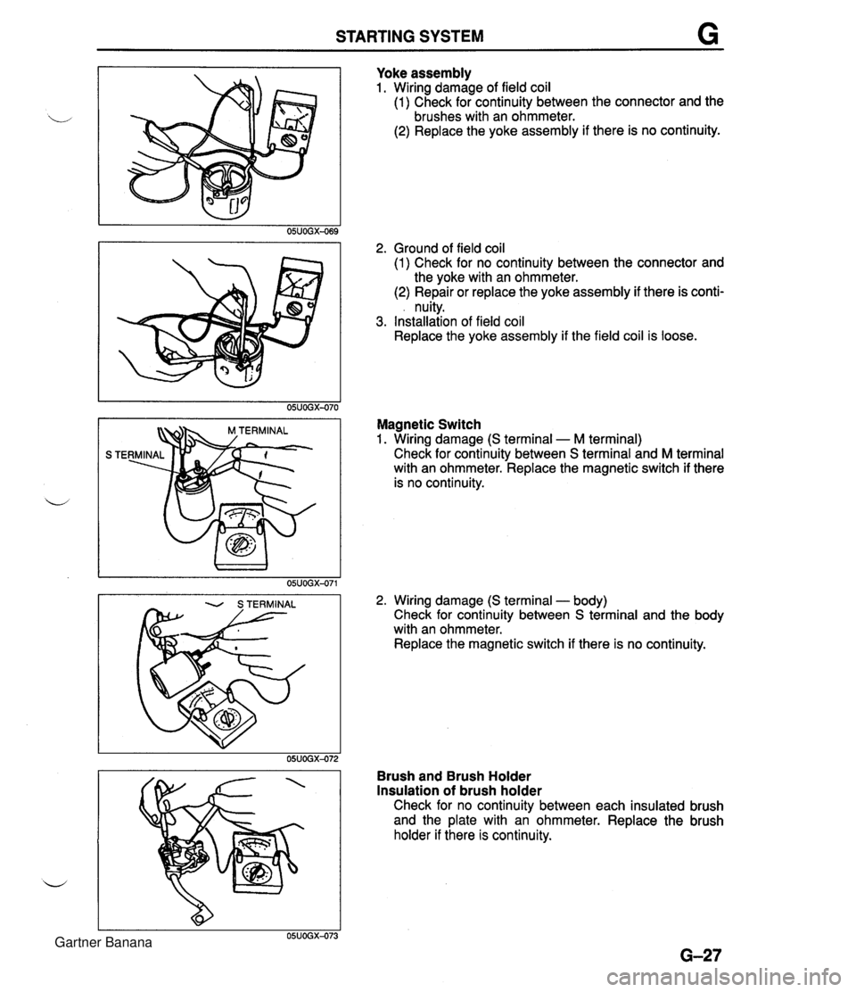
STARTING SYSTEM Yoke assembly 1. Wiring damage of field coil (1) Check for continuity between the connector and the brushes with an ohmmeter. (2) Replace the yoke assembly if there is no continuity. 2. Ground of field coil (1) Check for no continuity between the connector and the yoke with an ohmmeter. (2) Repair or replace the yoke assembly if there is conti- . nuity. 3. Installation of field coil Replace the yoke assembly if the field coil is loose. Magnetic Switch 1. Wiring damage (S terminal - M terminal) Check for continuity between S terminal and M terminal with an ohmmeter. Replace the magnetic switch if there is no continuity. 2. Wiring damage (S terminal - body) Check for continuity between S terminal and the body with an ohmmeter. Replace the magnetic switch if there is no continuity. Brush and Brush Holder Insulation of brush holder Check for no continuity between each insulated brush and the plate with an ohmmeter. Replace the brush holder if there is continuity. Gartner Banana
Page 335 of 1708

STARTING SYSTEM LIMIT 1 I 45UOGX-043 STARTER INTERLOCK SWITCH (MT) Brush If the brushes are worn beyond the wear limit or if the wear is near the limit, replace the brushes. CONTACT PLATES IGNITION SWITCH mm {in} IG1 ROD Standard Wear limit INTERLOCK SWITCH 62-7 - STARTER MT 17 (0.67) 11.5 (0.45) The clutch pedal must be depressed during starting for battery power to be supplied to the starter. AT 17.5 (0.69) 12.0 (0.47) Inspection 1. Disconnect the interlock switch connector. 2. Check continuity of the switch with an ohmmeter. Pedal Depressed Released Continuity Yes No 1 3. If not as specified, replace the interlock switch. Gartner Banana
Page 336 of 1708

Before beginning any service procedure. refer to section T of this manual for air bag system service warnlngs and audio antitheft system alarm conditions . i, CLUTCH INDEX ....................................... H- 2 OUTLINE ..................................... H- 3 SPECIFICATIONS ........................... H- 3 TROUBLESHOOTING GUIDE .................. H- 3 CLUTCH FLUID ............................... H- 4 ............................. PREPARATION H- 4 ............................ REPLACEMENT H- 4 .............................. CLUTCH PEDAL H- 5 .............................. ADJUSTMENT H- 5 REMOVAL / INSPECTION / INSTALLATION .... H- 6 ................. CLUTCH MASTER CYLINDER H- 7 PREPARATION ............................. H- 7 REMOVAL / INSTALLATION .................. H- 8 AIR BLEEDING ............................. H- 9 OVERHAUL ................................ H-10 CLUTCH RELEASE CYLINDER ................ H-12 PREPARATION ............................. H-12 REMOVAL / INSTALLATION .................. H-12 AIR BLEEDING (REFER TO PAGE H-9.) OVERHAUL ............................... H-13 CLUTCH UNIT ................................ H-14 PREPARATION ............................. H-14 REMOVAL / INSTALLATION .................. H-14 CLUTCH RELEASE COLLAR .................. H-17 INSPECTION ............................... H-17 CLUTCH COVER ............................. H-17 INSPECTION ............................... H-17 CLUTCH DISC ................................ H-17 INSPECTION ............................... H-17 PILOT BEARING .............................. H-18 INSPECTION ............................... H-18 FLYWHEEL ................................... H-18 INSPECTION ............................... H-18 35UOHX-001 Gartner Banana
Page 337 of 1708

H INDEX INDEX 1 . Clutch pedal ................ Adjustment page H- 5 Removal / Inspection / ............... Installation page H- 6 2. Clutch master cylinder ....... Removal I Installation page H- 8 .................. Overhaul page H-10 ............... Air bleeding page H- 9 3. Clutch release cylinder ....... Removal I Installation page H-12 .................. Overhaul page H-13 ............... Air bleeding page H- 9 4. Clutch release collar ....... Removal / Installation page H-14 ................. Inspection page H-17 SERVICE, SECTION F 5. Clutch release fork ....... Removal / Installation page H-14 6. Clutch cover ....... Removal / Installation page H-14 ................. Inspection page H-17 7. Clutch disc ....... Removal 1 Installation page H-14 ................. Inspection page H-17 8. Pilot bearing ....... Removal I Installation page H-14 ................. Inspection page H-18 9. Flywheel Removal / Installation ....... page H-14 ................. Inspection page H-18 Gartner Banana
Page 338 of 1708

OUTLINE, TROUBLESHOOTING GUIDE H OUTLINE SPECIFICATIONS I Clutch control L' Clutch cover Clutch disc Clutch pedal - Enginerrransmission BP DOHC item - M15M-D 1 Master cvlinder inne I Hydraulic Inner diameter mm {in) I 150 (5.91) I Pressure plate side I n n rn cr Tvpe . . Set load N {kgf, Ibf) Outer diameter mm {in) Pedal ratio 6.13 Full stroke mm {in) I 120 (4.72) Diaphraam spring .-.- 4,310 (440,968) 21 5 18.46) . - Height mm {in) * diameter mm {in) TROUBLESHOOTING GUIDE . - I 75--185 i6.89--7.283 15.87 (0.625) . - Release cylinder inner diameter mm {in) Clutch fluid I Problem I Possible Cause 19.05 i0.750) FMVSS116 DOT-3 Clutch disc facing surface hardened or oil on surface Pressure plate damaged u Diaphragm spring damaged or weak lnsufficient clutch pedal play I Slipping I Clutch disc facing worn excessively I Flywheel damaged Faulty disengagement I Clutch disc damaged or excessive runout Clutch disc spines rusted or worn Oil on clutch disc facing Diaphragm spring weak Excessive clutch pedal play Insufficient clutch fluid Leakage of clutch fluid I 1 Clutch disc facing hardened or damaged Clutch vibrates when accelerating I I Clutch disc facing rivets loose Oil on clutch disc facing Torsion dampers weak Clutch pedal stlcks Abnormal noise Pressure plate damaged or excessive runout Flywheel surface hardened or damaged Loose or worn engine mount Pedal shaft not pro~erlv lubricated Clutch release collar damaged Poor lubrication of release collar sleeve Torsion dampers weak Excessive crankshaft end play I I Pilot bearing worn or damaged I I Worn ~ivot points of release fork Action Replace Repair or replace Repair or replace Replace Adjust ~ebair or replace Replace Remove rust or replace Repair or replace Replace Adjust Add fluid Locate and repair or replace Repair or replace Replace Repair or replace Replace Replace Repair or replace Tighten or replace Lubricate or replace Replace Lubricate or replace Replace Repair Replace Repair or replace Page H-14 H-14 H-14 H-14 H-14 H-14 section B H- 6 H-14 H-14 H-14 section B H-14 H-14 45UOHX-OC Gartner Banana
Page 339 of 1708
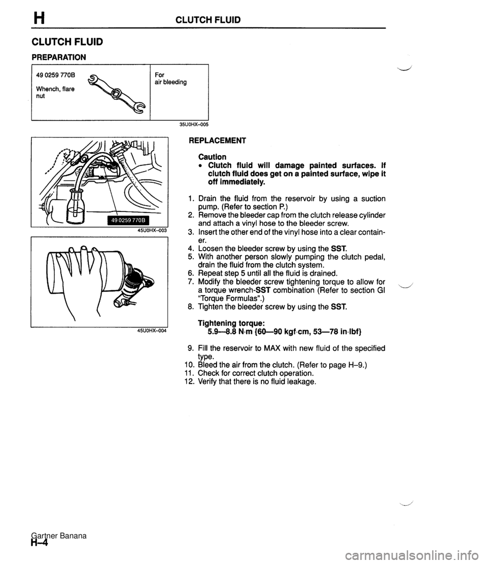
H CLUTCH FLUID CLUTCH FLUID PREPARATION 49 0259 7708 For air bleeding Whench, flare nut REPLACEMENT Caution Clutch fluid will damage painted surfaces. If clutch fluid does get on a painted surface, wipe it off immediately. 1. Drain the fluid from the reservoir by using a suction pump. (Refer to section P.) 2. Remove the bleeder cap from the clutch release cylinder and attach a vinyl hose to the bleeder screw. 3. Insert the other end of the vinyl hose into a clear contain- er. 4. Loosen the bleeder screw by using the SST. 5. With another person slowly pumping the clutch pedal, drain the fluid from the clutch system. 6. Repeat step 5 until all the fluid is drained. 7. Modify the bleeder screw tightening torque to allow for ,-, a torque wrench-SST combination (Refer to section GI "Torque Formulas".) 8. Tighten the bleeder screw by using the SST. Tightening torque: 5.9--8.8 N.m (60-90 kgf.cm, 53-78 in4bf) 9. Fill the reservoir to MAX with new fluid of the specified type. 10. Bleed the air from the clutch. (Refer to page H-9.) 11. Check for correct clutch operation. 12. Verifv that there is no fluid leakaae. Gartner Banana
Page 340 of 1708

CLUTCHPEDAL H Minimum disengagement height: 68mm (2.68 in) (With carpet) CLUTCHPEDAL ADJUSTMENT Height lnspection 1. Measure the distance from the upper surface of the ped- al pad to the carpet. Pedal height: 175--185mm (6.89-7.28 in) (With carpet) 2. If necessary, adjust the height. Adjustment 1. Disconnect the clutch switch connector. 2. Loosen locknut @ and turn clutch switch @I until the height is correct. I 3. Tighten locknut @. Tightening torque: l3.Cl7.6 N-m (1 4Gl8O kgf-cm, 122-1 56 in-IM) 4. After adjustment, inspect the free play. Free Play lnspection 1. Depress the clutch pedal by hand until clutch resistance is felt. Free play: 0.6-3.lmm (0.02-0.12 in) Total free play: S13mm (0.20-0.51 in) 2. If necessary, adjust the free play. Adjustment 1. Loosen locknut 0 and turn push rod 03 until free play is correct. 2. Verify that the disengagement height as measured from the upper surface of the pedal pad to the carpet is correct when the pedal is fully depressed. 3. Tighten locknut 0. Tightening torque: 11 .&l6.6 N.m (120-1 70 kgtcm, 105--147 in.lbf} 4. After adjustment, inspect the height. Gartner Banana