check oil MAZDA MX-5 1994 Service Manual
[x] Cancel search | Manufacturer: MAZDA, Model Year: 1994, Model line: MX-5, Model: MAZDA MX-5 1994Pages: 1708, PDF Size: 82.34 MB
Page 410 of 1708

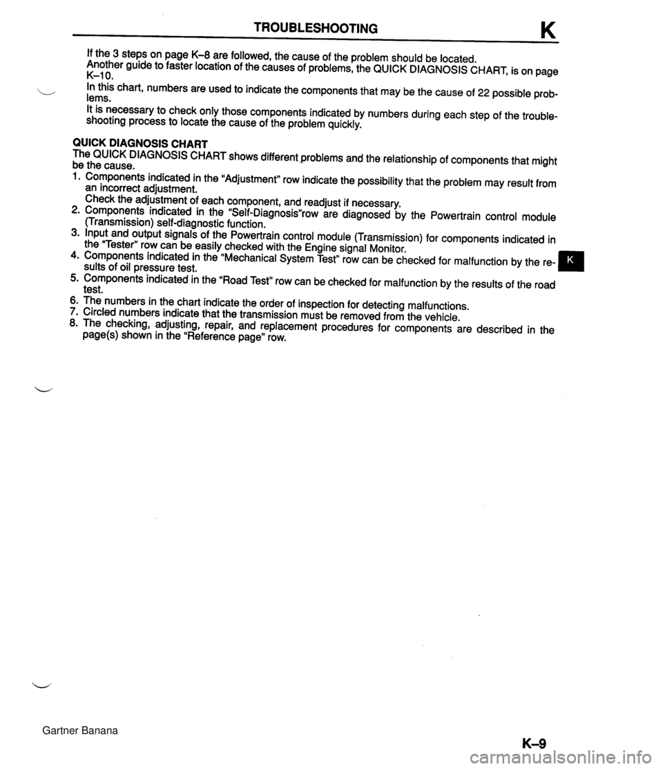
TROUBLESHOOTING If the 3 steps on page K-8 are followed, the cause of the problem should be located. Another guide to faster location of the causes of problems, the QUICK DIAGNOSIS CHART, is on page K-1 0. b In this chart, numbers are used to indicate the components that may be the cause of 22 possible prob- lems. It is necessary to check only those components indicated by numbers during each step of the trouble- shooting process to locate the cause of the problem quickly. QUICK DIAGNOSIS CHART The QUICK DIAGNOSIS CHART shows different .problems and the relationship of components that might be the cause. 1. Components indicated in the "Adjustment" row indicate the possibility that the problem may result from an incorrect adjustment. Check the adjustment of each component, and readjust if necessary. 2. Components indicated in the "Self-DiagnosisWrow are diagnosed by the Powertrain control module (Transmission) self-diagnostic function. 3. Input and output signals of the Powertrain control module (Transmission) for components indicated in the "Tester" row can be easily checked with the Engine signal Monitor. 4. Components indicated in the "Mechanical System Test" row can be checked for malfunction by the re- sults of oil pressure test. 5. Components indicated in the "Road Test" row can be checked for malfunction by the results of the road test. 6. The numbers in the chart indicate the order of inspection for detecting malfunctions. 7. Circled numbers indicate that the transmission must be removed from the vehicle. 8. The checking, adjusting, repair, and replacement procedures for components are described in the page(s) shown in the "Reference page" row. Gartner Banana
Page 423 of 1708

K MECHANICAL SYSTEM TEST MECHANICAL SYSTEM TEST PREPARATION SST STALL TEST 49 0378 400A Gauge set, oil pressure 49 801 9 901 Gauge, oil pressure For oil pressure test For oil pressure test This test is performed to determine if there is slippage of the friction elements or malfunction of the hy- draulic components. Preparation 1. Check the engine coolant, engine oil, and ATF levels before testing. 2. Warm the engine thoroughly to raise the ATF temperature to operating level (50--80°C, 122-176°F). 3. Engage the parking brake and use wheel chocks at the front and rear of the wheels. ENGAGE PARKING BRAKE WARM UP ENGINE COOLANT LEVEL ENGINE OIL LEVEL TEMPERATURE 60-70°C (1 40-1 58°F) ATF LEVEL Gartner Banana
Page 427 of 1708

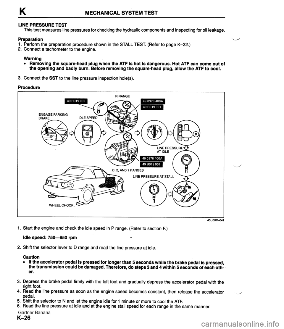
K MECHANICAL SYSTEM TEST LINE PRESSURE TEST This test measures line pressures for checking the hydraulic components and inspecting for oil leakage. Preparation d 1. Perform the preparation procedure shown in the STALL TEST. (Refer to page K-22.) 2. Connect a tachometer to the engine. Warning Removing the square-head plug when the ATF is hot is dangerous. Hot ATF can come out of the opening and badly burn. Before removing the square-head plug, allow the ATF to cool. 3. Connect the SST to the line pressure inspection hole(s). Procedure 1. Start the engine and check the idle speed in P range. (Refer to section F.) Idle speed: 750--850 rpm * 2. Shift the selector lever to D range and read the line pressure at idle. Caution If the accelerator pedal is pressed for longer than 5 seconds while the brake pedal is pressed, the transmission could be damaged. Therefore, do steps 3 and 4 within 5 seconds of each oth- er. 3. Depress the brake pedal firmly with the left foot and gradually depress the accelerator pedal with the right foot. 4. Read the line pressure as soon as the engine speed becomes constant, then release the accelerator .- pedal. 5. Shift the selector to N and let the engine idle for 1 minute or more to cool the ATF. 6. Read the line pressure at idle and at the engine stall speed for each range in the same manner. Gartner Banana
Page 430 of 1708

ROAD TEST K ROAD TEST A road test is necessary to inspect for problems in the different gear ranges. If a range or function tar- b geted by the road test is found to have any problem, refer to the ELECTRONIC SYSTEM COMPONENT segment or the TRANSMISSION, OIL COOLER, DRIVE PLATE, and SHIFT MECHANISM segments of this section. Do the road test only when the ATF is 50-80°C (1 22-1 76°F). D-RANGE TEST Shift Point, Shift Pattern, and Shift Shock 1. Shift the selector lever to D range and select the Normal mode. 2. Accelerate the vehicle with half-and wide open throttle opening. 3. Verify that 1-2, 2-3, and 3-4 upshifts, downshifts, and lockup are obtained. The shift points must be as shown in the D range (Normal) shift diagram. Note There is fourth gear is any of the following conditions. A The cruise control is operating, and there is an 8kmIh (5 mph} difference between the preset cruise speed and the vehicle speed. B The SET or RESUME switch is ON. There is no lockup when water temperature is below 50°C (1 22°F) or in the throttle valve closed posi- tion. 4. Check the upshifts for shift shock or slippage in the same manner. 5. While driving in overdrive, shift the selector lever to S range and verify that 4-3 downshift immediately occurs, then decelerate and verify that engine braking effect is felt in only third gear and 2nd gears. D-range (Normal) shift diagram p'yJ ..,,*sw.. LOCKUP AVAILABLE WHEN ACCELERATING AND CRUSING LOCKUP AVAILABLE WHEN COASTING 0 20 (1 2) 40 (25) 60 (37) 80 {50) 100 (63) 1 20 (75) 140 (87) 1 60 (99) VEHICLE SPEED kmlh {mph) Gartner Banana
Page 437 of 1708

K AUTOMATIC TRANSMISSION FLUID (ATF) Fluid leaks Check for fluid leaks of the transmission as shown below, and repair or replace as necessary. 1. Gaskets, O-ring, and plugs 2. Oil hoses, oil pipes, and connections 3. Oil cooler @ .... O-RING @ .... GASKET 0 .... OIL SEAL 0 .... PLUG @ .... OTHER Gartner Banana
Page 438 of 1708

AUTOMATIC TRANSMISSION FLUID (ATF) K REPLACEMENT 1. On level ground, jack up the vehicle and support it evenly on safety stands. Warning When the transmission and the ATF are hot, they can cause burns to the skin. Allow the transmis- sion and the ATF to cool before doing this proce- dure. 2. Loosen the oil pan installation bolts, and drain the ATF into a container. 3. Remove the oil pan and gasket. 4. Clean the oil pan and the magnet. 5. Install the oil pan along with a new gasket. Tightening torque: 5.9-7.8 N-m (60-80 kgfecm, 53-69 in-lbf) 6. Add approximately 4.0 L (4.2 US qt, 3.5 Imp qt} ATF, and check the ATF level. (Refer to page K-35.) Specified ATF: DexronmII or M-I11 Gartner Banana
Page 447 of 1708

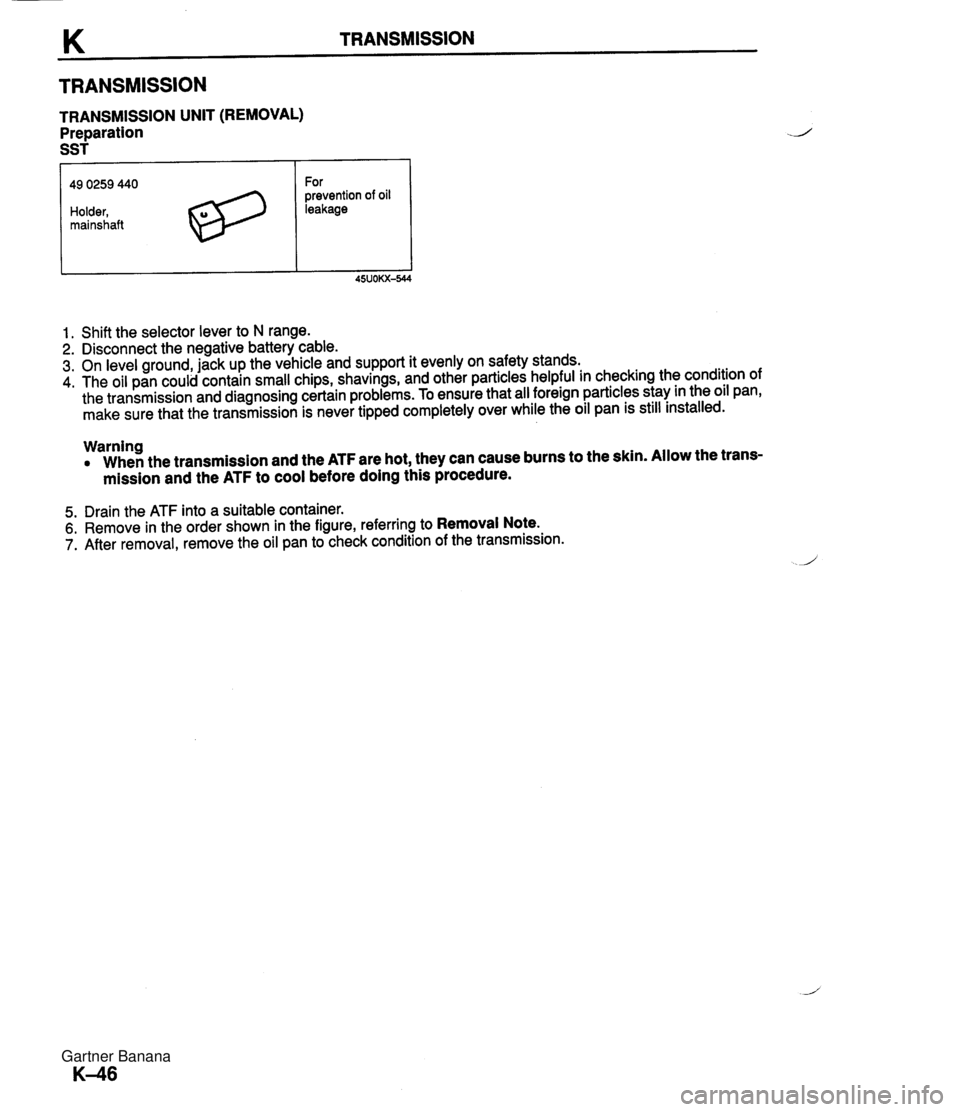
TRANSMISSION TRANSMISSION UNIT (REMOVAL) Preparation SST 49 0259 440 Holder, mainshaft For prevention of oil leakage 1. Shift the selector lever to N range. 2. Disconnect the negative battery cable. 3. On level ground, jack up the vehicle and support it evenly on safety stands. 4. The oil pan could contain small chips, shavings, and other particles helpful in checking the condition of the transmission and diagnosing certain problems. To ensure that all foreign particles stay in the oil pan, make sure that the transmission is never tipped completely over while the oil pan is still installed. Warning When the transmission and the ATF are hot, they can cause burns to the skin. Allow the trans- mission and the ATF to cool before doing this procedure. 5. Drain the ATF into a suitable container. 6. Remove in the order shown in the figure, referring to Removal Note. 7. After removal, remove the oil pan to check condition of the transmission. Gartner Banana
Page 451 of 1708

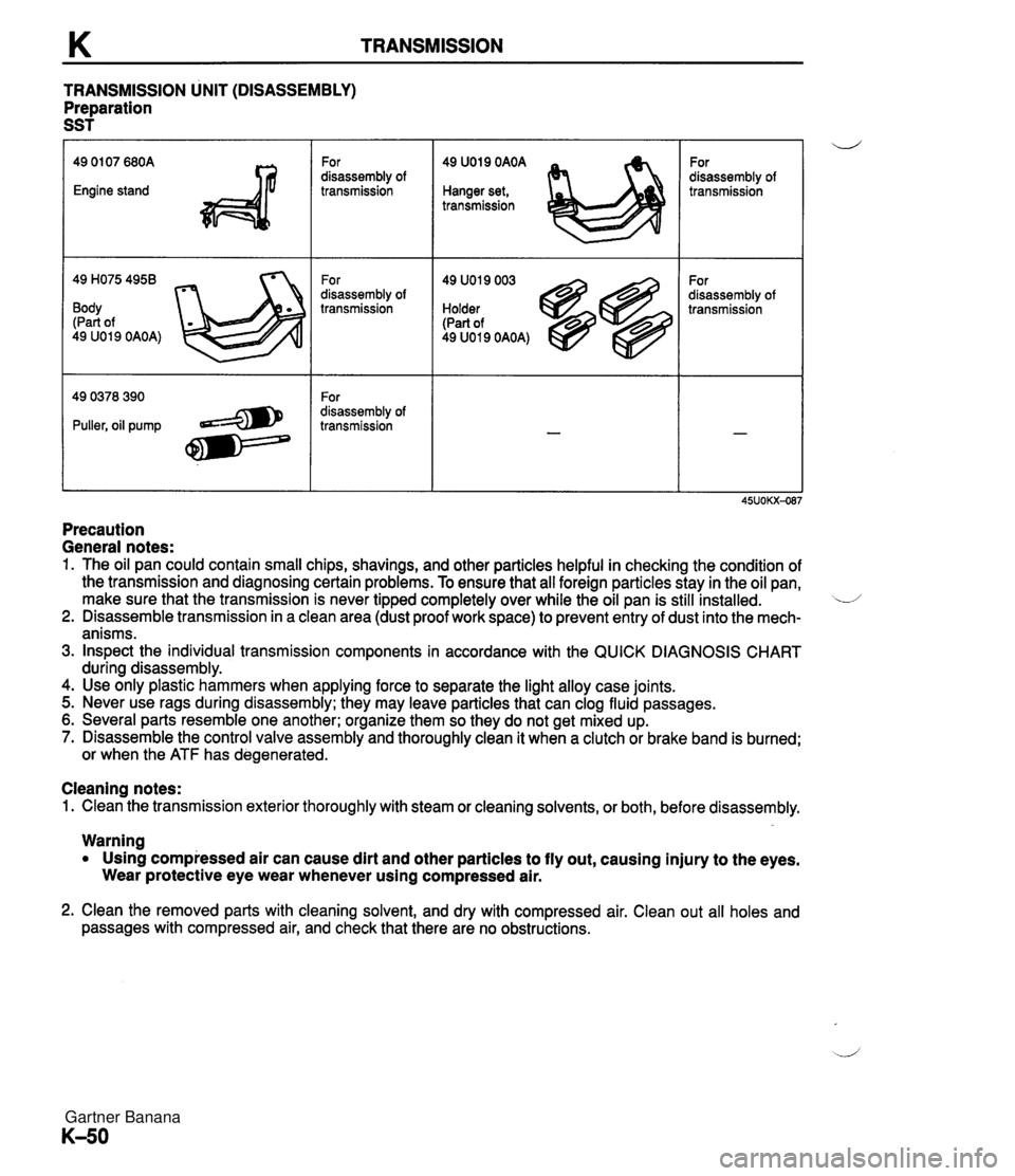
TRANSMISSION TRANSMISSION UNIT (DISASSEMBLY) Preparation SST 49 H075 4958 Body (Part of 49 U019 OAOA) For disassembly of transmission For disassembly of transmission For disassembly of transmission 49 U019 OAOA Hanger set, transmission 49 U019 003 Holder (Part of 49 U019 OAOA) For disassembly of transmission For disassembly of transmission Precaution General notes: 1. The oil pan could contain small chips, shavings, and other particles helpful in checking the condition of the transmission and diagnosing certain problems. To ensure that all foreign particles stay in the oil pan, make sure that the transmission is never tipped completely over while the oil pan is still installed. L/ 2. Disassemble transmission in a clean area (dust proof work space) to prevent entry of dust into the mech- anisms. 3. Inspect the individual transmission components in accordance with the QUICK DIAGNOSIS CHART during disassembly. 4. Use only plastic hammers when applying force to separate the light alloy case joints. 5. Never use rags during disassembly; they may leave particles that can clog fluid passages. 6. Several parts resemble one another; organize them so they do not get mixed up. 7. Disassemble the control valve assembly and thoroughly clean it when a clutch or brake band is burned; or when the ATF has degenerated. Cleaning notes: 1. Clean the transmission exterior thoroughly with steam or cleaning solvents, or both, before disassembly. Warning Using compressed air can cause dirt and other particles to fly out, causing injury to the eyes. Wear protective eye wear whenever using compressed air. 2. Clean the removed parts with cleaning solvent, and dry with compressed air. Clean out all holes and passages with compressed air, and check that there are no obstructions. Gartner Banana
Page 456 of 1708

TRANSMISSION K Procedure 1. Place wooden blocks under the transmission at the con- verter housing and the extension housing positions. 2. Remove the oil pan and gasket. Examine any material found in the pan or on the magnet to determine the condition of the transmission. Clutch facing material . . . . . Drive plate and brake band wear Steel (magnetic) . . . . . . . . . . Bearing, gear, and driven plate wear Aluminum (nonmagnetic) . . Bushings or cast alumi- num parts wear If large amounts of material are found, replace the torque converter and carefully check the transmission for the cause. 3. Install the oil pan and gasket with a few bolts to protect the valve body. 4. Remove the vacuum diaphragm, lockup control solenoid valve, vehicle speed pulse generator, and O-rings. 5. Remove the parwneutral switch. 6. Remove the speedometer driven gear from the exten- sion housing. 7. Remove the O-ring from the speedometer driven gear. Gartner Banana
Page 462 of 1708

TRANSMISSION K 41. Remove the oil distributor. 42. Remove the bearing. TORQUE CONVERTER Inspection 1. Check the outside of the converter for damage and cracks, and replace the torque converter if there is any problem. 2. Check for rust on the pilot hub or on the boss, and re- move the rust completely if there is any. Washing inside the converter 1. Drain any ATF remaining in the converter. 2. Pour in solvent (0.5 L, 0.5 US qt, 0.4 Imp qt). 3. Shake the converter to clean the inside. Pour out the sol- vent. 4. Clean the inside of the converter with compressed air so that the inside is completely empty. 5. Pour in ATF. 6. Shake the converter to clean the inside. Pour out the ATF. Gartner Banana