check oil MAZDA MX-5 1994 Manual Online
[x] Cancel search | Manufacturer: MAZDA, Model Year: 1994, Model line: MX-5, Model: MAZDA MX-5 1994Pages: 1708, PDF Size: 82.34 MB
Page 702 of 1708
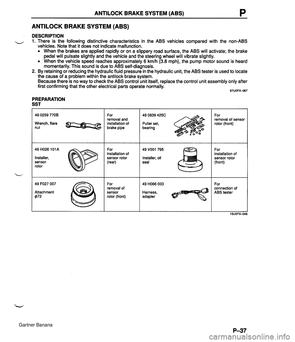
ANTILOCK BRAKE SYSTEM (ABS) P ANTILOCK BRAKE SYSTEM (ABS) DESCRIPTION - 1. There is the following distinctive characteristics in the ABS vehicles compared with the non-ABS vehicles. Note that it does not indicate malfunction. When the brakes are applied rapidly or on a slippery road surface, the ABS will activate; the brake pedal will pulsate slightly and the vehicle and the steering wheel will vibrate slightly. When the vehicle speed reaches approximately 6 kmh (3.8 mph}, the pump motor sound is heard momentarily. This sound is due to ABS self-diagnosis. 2. By retaining or reducing the hydraulic fluid pressure in the hydraulic unit, the ABS tester is used to locate the cause of a problem within the antilock brake system. Because there is no way to check the ABS control unit itself, replace the control unit assembly only after first confirming that the other electrical parts operate normally. PREPARATION SST Wrench, flare nut 49 H026 101 A Installer, sensor rotor 49 F027 007 Attachment 072 For removal and installation of brake pipe For installation of sensor rotor (rear) For removal of sensor rotor (front) 49 0839 425C Puller set, bearing Installer, oil seal Harness, adapter For removal of sensor rotor (front) For installation of sensor rotor (front) For connection of ABS tester Gartner Banana
Page 730 of 1708
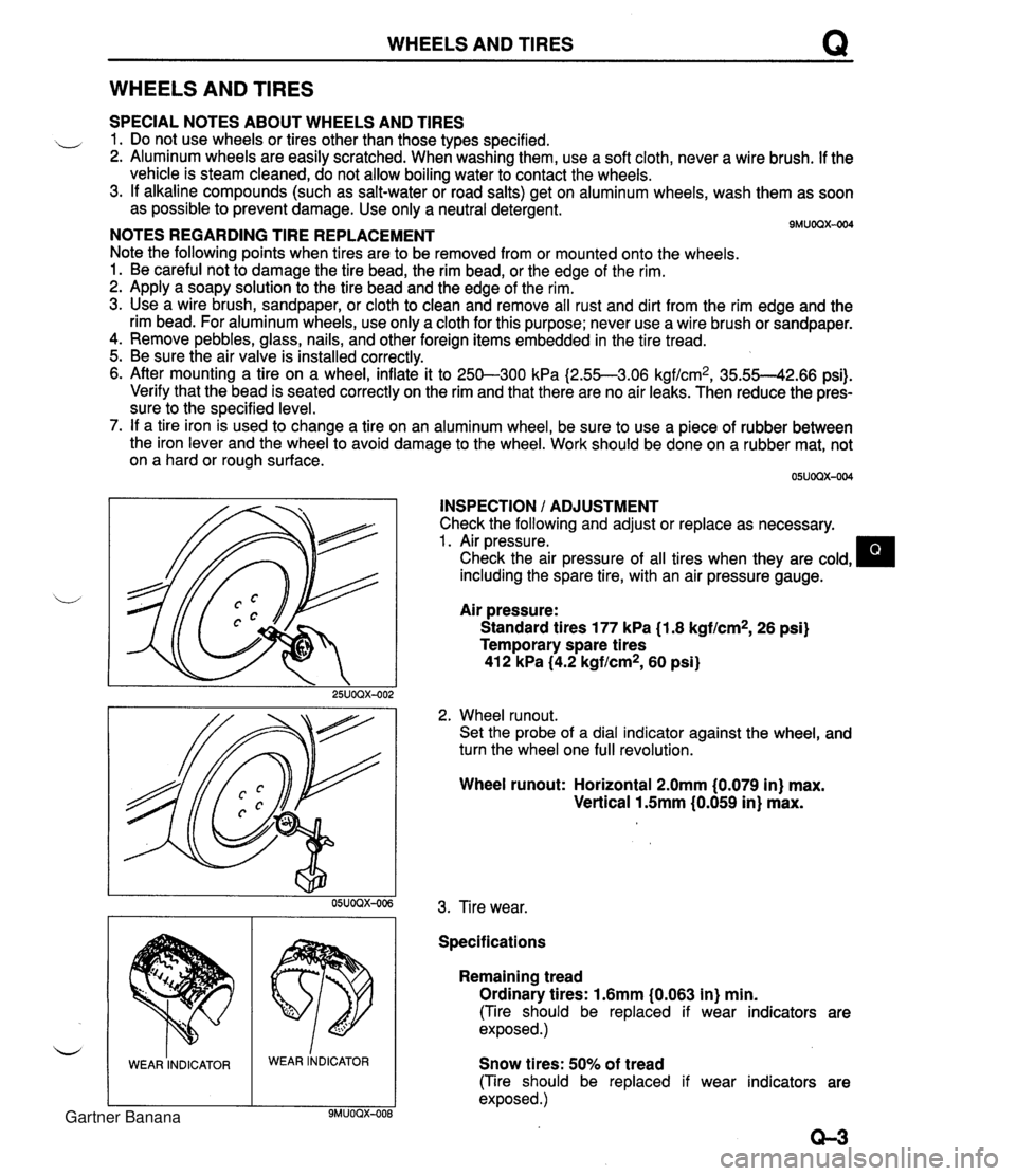
WHEELS AND TIRES Q WHEELS AND TIRES SPECIAL NOTES ABOUT WHEELS AND TIRES ,, 1. Do not use wheels or tires other than those types specified. 2. Aluminum wheels are easily scratched. When washing them, use a soft cloth, never a wire brush. If the vehicle is steam cleaned, do not allow boiling water to contact the wheels. 3. If alkaline compounds (such as salt-water or road salts) get on aluminum wheels, wash them as soon as possible to prevent damage. Use only a neutral detergent. - - 9MUOQX-004 NOTES REGARDING TIRE REPLACEMENT Note the following points when tires are to be removed from or mounted onto the wheels. 1. Be careful not to damage the tire bead, the rim bead, or the edge of the rim. 2. Apply a soapy solution to the tire bead and the edge of the rim. 3. Use a wire brush, sandpaper, or cloth to clean and remove all rust and dirt from the rim edge and the rim bead. For aluminum wheels, use only a cloth for this purpose; never use a wire brush or sandpaper. 4. Remove pebbles, glass, nails, and other foreign items embedded in the tire tread. 5. Be sure the air valve is installed correctly. 6. After mounting a tire on a wheel, inflate it to 250-300 kPa I2.55--3.06 kgf/cm2, 35.55--42.66 psi). Verify that the bead is seated correctly on the rim and that there are no air leaks. Then reduce the pres- sure to the specified level. 7. If a tire iron is used to change a tire on an aluminum wheel, be sure to use a piece of rubber between the iron lever and the wheel to avoid damage to the wheel. Work should be done on a rubber mat, not on a hard or rough surface. INSPECTION / ADJUSTMENT Check the following and adjust or replace as necessary. 1. Air pressure. Check the air pressure of all tires when they are cold, including the spare tire, with an air pressure gauge. u Air pressure: Standard tires 177 kPa (1.8 kgf/cm2, 26 psi) Temporary spare tires 412 kPa (4.2 kgf/cm2, 60 psi) 2. Wheel runout. Set the probe of a dial indicator against the wheel, and turn the wheel one full revolution. WEAR INDICATOR Wheel runout: Horizontal 2.0mm (0.079 in) max. Vertical 1.5mm (0.059 in) max. WEAR lNDICAToR 3. Tire wear. Specifications Remaining tread Ordinary tires: 1.6mm (0.063 in) min. (Tire should be replaced if wear indicators are exposed.) Snow tires: 50% of tread (Tire should be replaced if wear indicators are exposed .) Gartner Banana
Page 738 of 1708
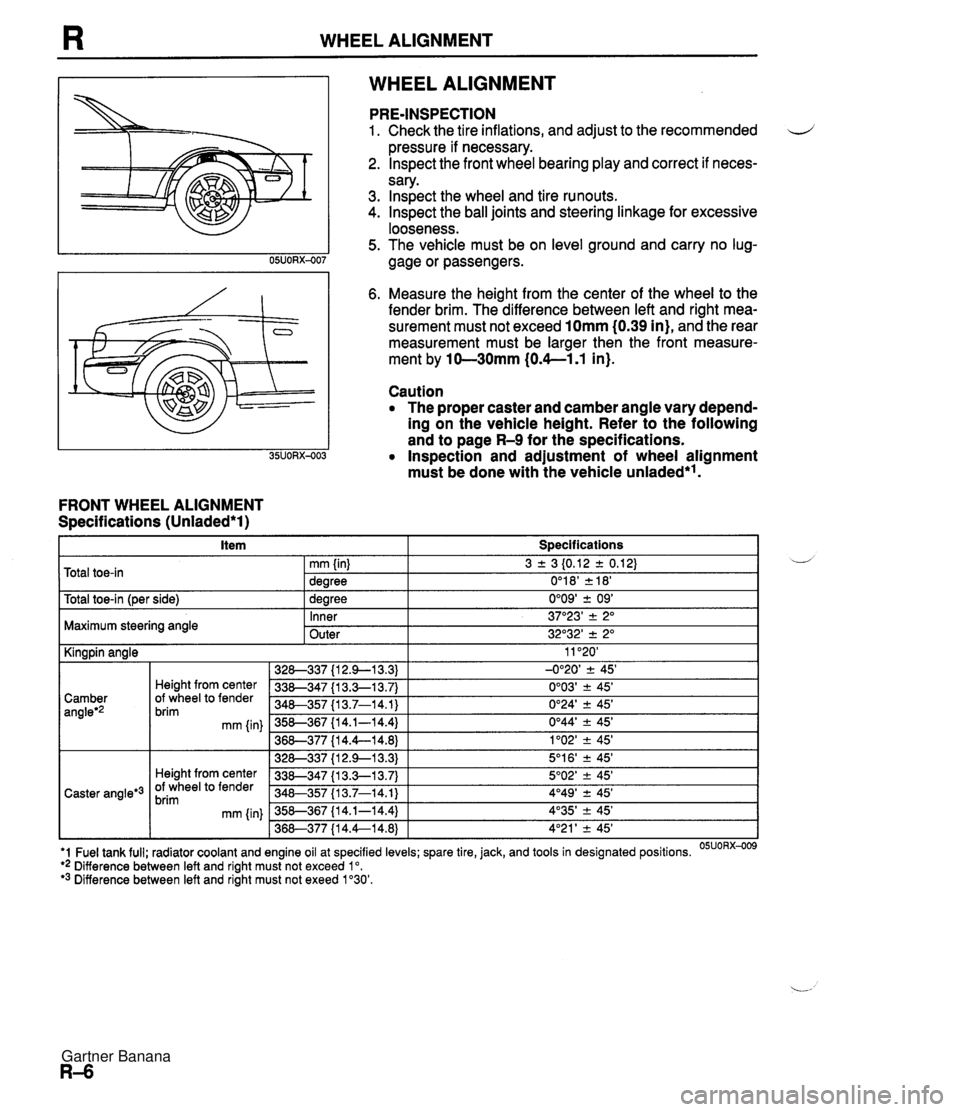
WHEEL ALIGNMENT WHEEL ALIGNMENT FRONT WHEEL ALIGNMENT Specifications (Unladed*l) PRE-INSPECTION 1. Check the tire inflations, and adjust to the recommended d pressure if necessary. 2. lnspect the front wheel bearing play and correct if neces- sary. 3. lnspect the wheel and tire runouts. 4. Inspect the ball joints and steering linkage for excessive looseness. 5. The vehicle must be on level ground and carry no lug- gage or passengers. 6. Measure the height from the center of the wheel to the fender brim. The difference between left and right mea- surement must not exceed 10mm (0.39 in), and the rear measurement must be larger then the front measure- ment by 10-30mm (0.4--1.1 in). Caution The proper caster and camber angle vary depend- ing on the vehicle height. Refer to the following and to page R-9 for the specifications. Inspection and adjustment of wheel alignment must be done with the vehicle unladed*'. . . I Y -- t~otal toe-in l~er side) I 1 dearee 0'09' + 09' I Total toe-in 3 2 3 I0.12 2 0.12) 0'1 8' 2 18' mm (in) dearee Maximum steering angle U - Inner Outer 11 '20' -0°20' 2 45' 0'03' ? 45' 0'24' 2 45' 0°44' -+ 45' 1'02' -+ 45' 5'1 6' ? 45' 5O02' -+ 45' 4O49' 2 45' 4'35' -+ 45' 4'21 ' -+ 45' I Kingpin angle 37"23' -+ 2" 32O32' 2 2" '1 Fuel tank full; radiator coolant and engine oil at specified levels; spare tire, jack, and tools in designated positions. OSUORX-009 ** Difference between left and right must not exceed lo. '3 Difference between left and right must not exeed 1'30'. 328-337 {I 2.9-1 3.3) 338-347 {I 3.3-1 3.7) 340-357 I13.7-14.1) 358-367 {I 4.1-14.4) 36&377 {I 4.4--14.8) 328-337 {I 2.9--13.3) 338-347 {I 3.3-1 3.7) 348-357 113.7-14.1) 358-367 {I 4.1-14.4) 368-377 {I 4.4--14.8) Camber angleg2 Caster angle*3 Height from center Of wheel to fender brim mm {in) Height from center Of wheel to fender brim mm (in) Gartner Banana
Page 746 of 1708
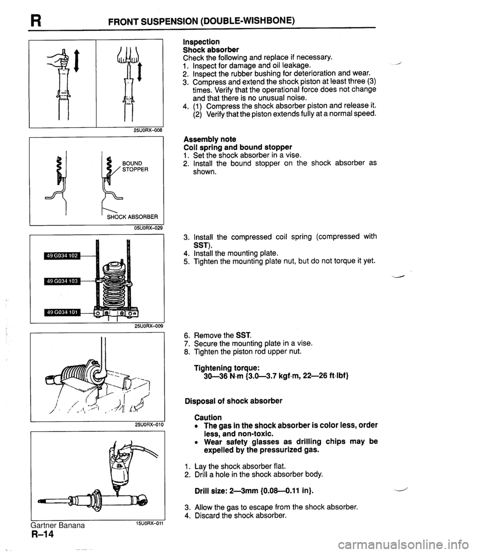
I3 FRONT SUSPENSION (DOUBLE-WISHBONE) I t'- SHOCK ABSORBER 05UORX-02 Inspection Shock absorber Check the following and replace if necessary. 1. lnspect for damage and oil leakage. 2. lnspect the rubber bushing for deterioration and wear. 3. Compress and extend the shock piston at least three (3) times. Verify that the operational force does not change and that there is no unusual noise. 4. (1) Compress the shock absorber piston and release it. (2) Verify that the piston extends fully at a normal speed. Assembly note Coil spring and bound stopper 1. Set the shock absorber in a vise. 2. Install the bound stopper on the shock absorber as shown. 3. lnstall the compressed coil spring (compressed with SST). 4. Install the mounting plate. 5. Tighten the mounting plate nut, but do not torque it yet. 6. Remove the SST. 7. Secure the mounting plate in a vise. 8. Tighten the piston rod upper nut. Tightening torque: 30-36 N.m (3.0-3.7 kgf.m, 22-26 ftdbf) Disposal of shock absorber Caution The gas in the shock absorber is color less, order less, and non-toxic. Wear safety glasses as drilling chips may be expelled by the pressurized gas. 1. Lay the shock absorber flat. 2. Drill a hole in the shock absorber body. Drill size: 2-3mm (0.08-0.11 in). 3. Allow the gas to escape from the shock absorber. 4. Discard the shock absorber. Gartner Banana
Page 873 of 1708
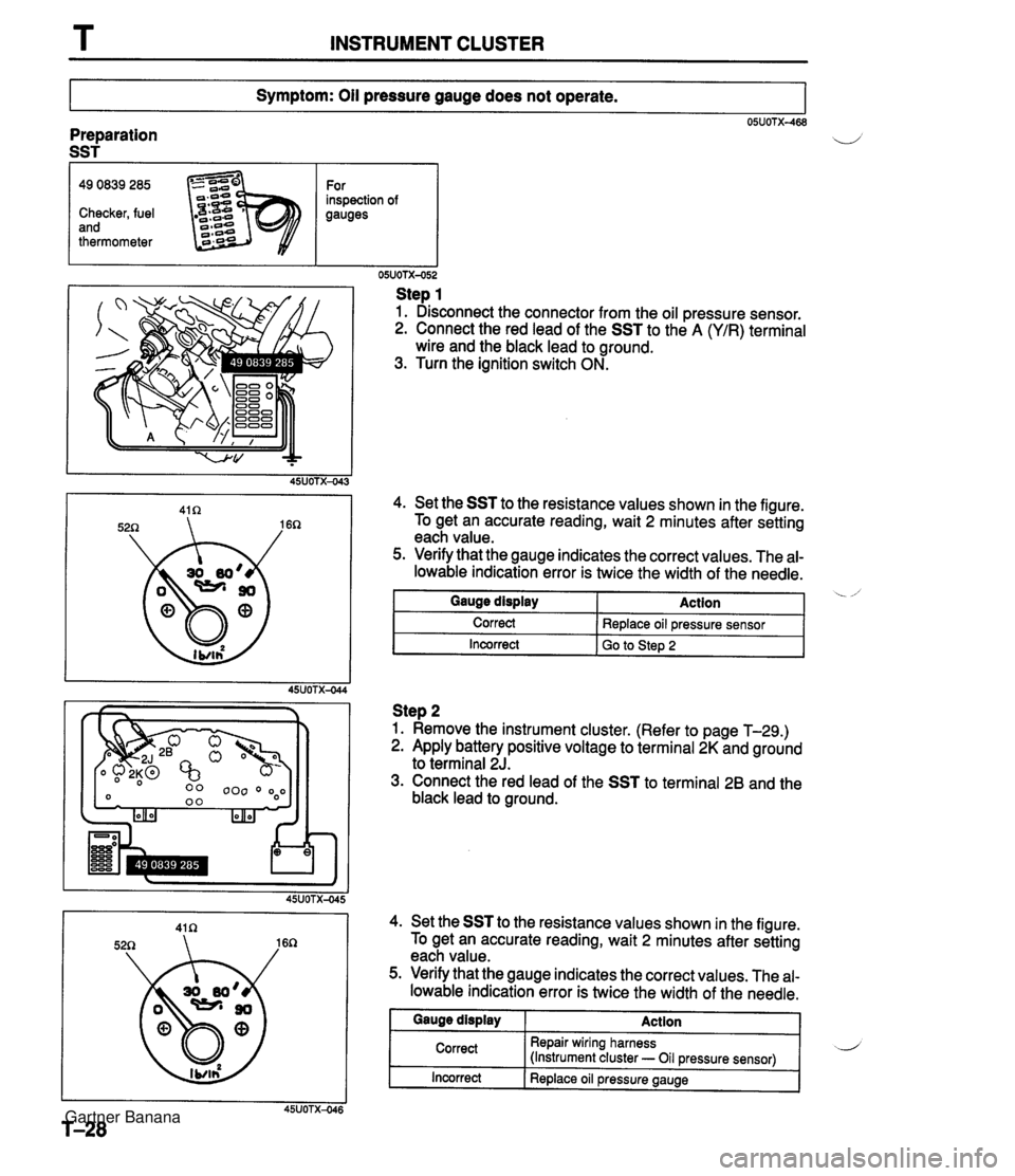
T INSTRUMENT CLUSTER Symptom: Oil pressure gauge does not operate. 05UOTX-468 Preparation SST I 49 0839 285 For inspection of Checker, fuel gauges and thermometer Step 1 1. Disconnect the connector from the oil pressure sensor. 2. Connect the red lead of the SST to the A (YIR) terminal wire and the black lead to ground. 3. Turn the ignition switch ON. 4. Set the SST to the resistance values shown in the figure. To get an accurate reading, wait 2 minutes after setting each value. 5. Verify that the gauge indicates the correct values. The al- lowable indication error is twice the width of the needle. I Incorrect I GO to step 2 Gauge display Correct Step 2 1. Remove the instrument cluster. (Refer to page T-29.) 2. Apply battery positive voltage to terminal 2K and ground to terminal 2J. 3. Connect the red lead of the SST to terminal 26 and the black lead to ground. Action Replace oil pressure sensor 4. Set the SST to the resistance values shown in the figure. To get an accurate reading, wait 2 minutes after setting each value. 5. Verify that the gauge indicates the correct values. The al- lowable indication error is twice the width of the needle. Incorrect I Replace oil pressure gauge Gauge display Correct Action Repair wiring harness (Instrument cluster - Oil pressure sensor) Gartner Banana
Page 876 of 1708
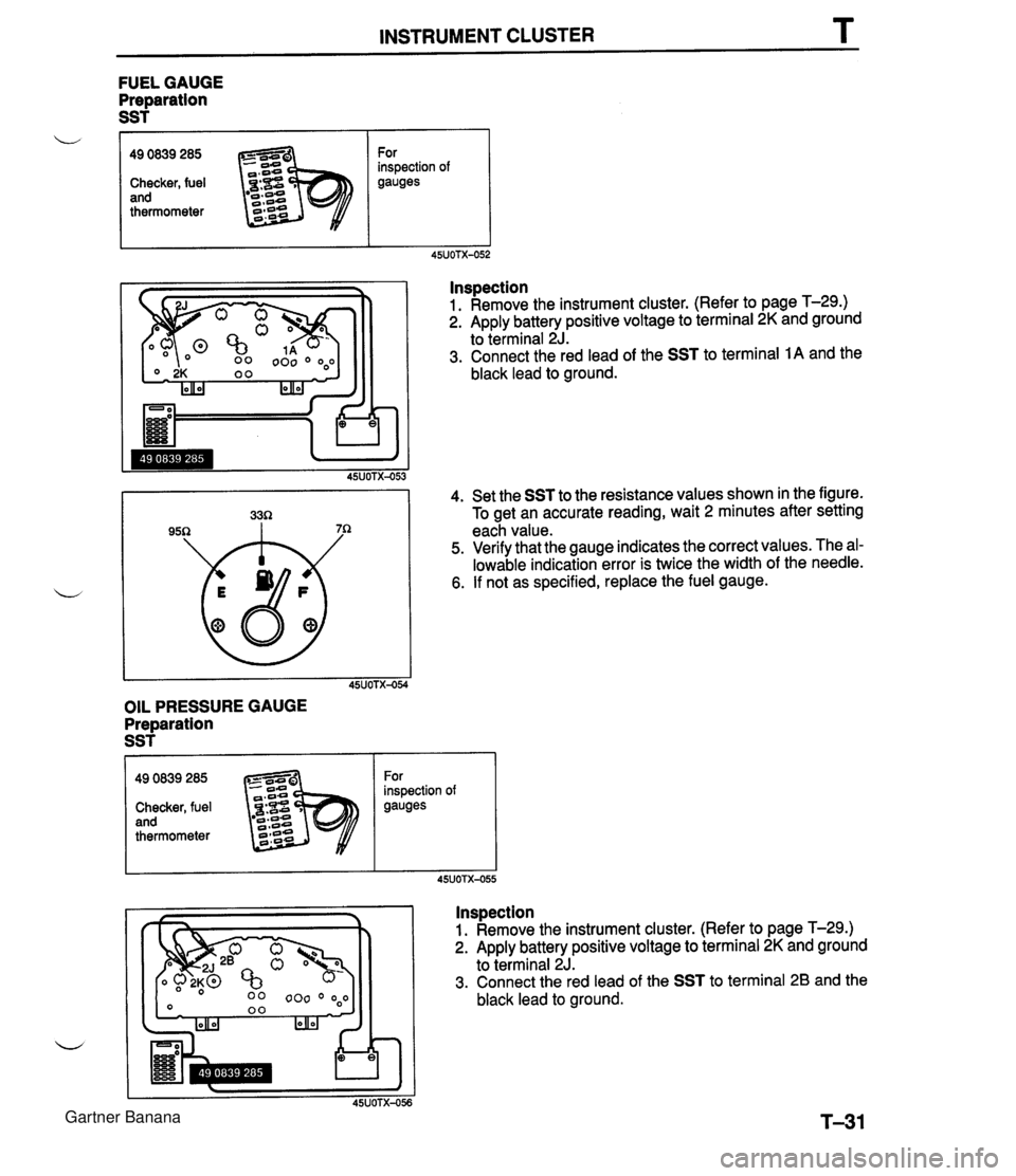
INSTRUMENT CLUSTER T FUEL GAUGE Preparation SST f OIL PRESSURE GAUGE Preparation SST L lnspection 1. Remove the instrument cluster. (Refer to page T-29.) 2. Apply battery positive voltage to terminal 2K and ground to terminal 2J. 3. Connect the red lead of the SST to terminal 1A and the black lead to ground. 4. Set the SST to the resistance values shown in the figure. To get an accurate reading, wait 2 minutes after setting each value. 5. Verify that the gauge indicates the correct values. The al- lowable indication error is twice the width of the needle. 6. If not as specified, replace the fuel gauge. 49 0839 285 Checker, fuel and thermometer For inspection of gauges Inspection 1. Remove the instrument cluster. (Refer to page T-29.) 2. Apply battery positive voltage to terminal 2K and ground to terminal 2J. 3. Connect the red lead of the SST to terminal 2B and the black lead to ground. 49 0839 285 Checker, fuel and thermometer For inspection of gauges Gartner Banana
Page 877 of 1708
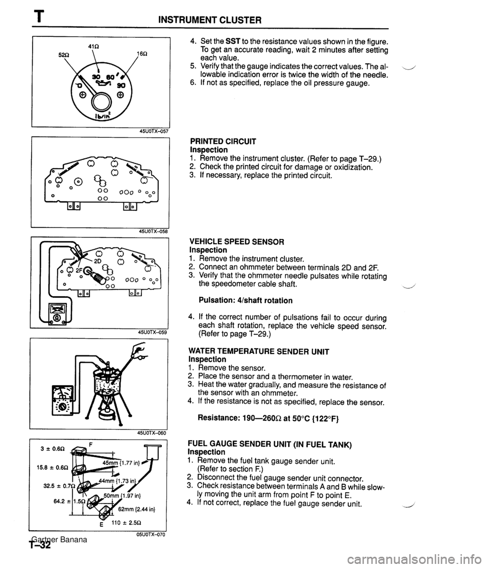
T INSTRUMENT CLUSTER 4. Set the SST to the resistance values shown in the figure. To get an accurate reading, wait 2 minutes after setting each value. 5. Verify that the gauge indicates the correct values. The al- \J lowable indication error is twice the width of the needle. 6. If not as specified, replace the oil pressure gauge. PRINTED CIRCUIT lnspection 1. Remove the instrument cluster. (Refer to page T-29.) 2. Check the printed circuit for damage or oxidization. 3. If necessary, replace the printed circuit. VEHICLE SPEED SENSOR lnspection 1. Remove the instrument cluster. 2. Connect an ohmmeter between terminals 2D and 2F. 3. Verify that the ohmmeter needle pulsates while rotating the speedometer cable shaft. ~ Pulsation: Ushaft rotation 4. If the correct number of pulsations fail to occur during each shaft rotation, replace the vehicle speed sensor. (Refer to page T-29.) WATER TEMPERATURE SENDER UNlT lnspection 1. Remove the sensor. 2. Place the sensor and a thermometer in water. 3. Heat the water gradually, and measure the resistance of the sensor with an ohmmeter. 4. If the resistance is not as specified, replace the sensor. Resistance: 190-260Q at 50°C (1 22°F) FUEL GAUGE SENDER UNlT (IN FUEL TANK) lnspection 1. Remove the fuel tank gauge sender unit. (Refer to section F.) 2. Disconnect the fuel gauge sender unit connector. 3. Check resistance between terminals A and B while slow- ly moving the unit arm from point F to point E. 4. If not correct, replace the fuel gauge sender unit. 2 Gartner Banana
Page 1073 of 1708
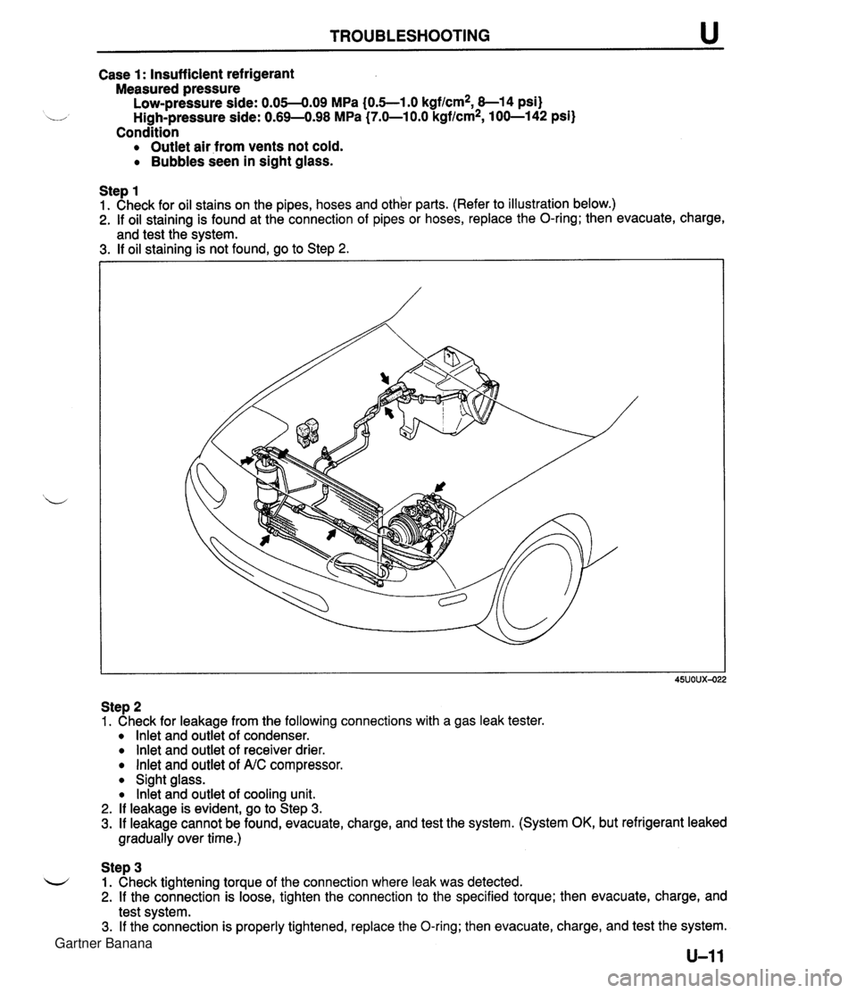
TROUBLESHOOTING Case 1: Insufficient refrigerant Measured pressure Low-pressure side: 0.05-4.09 MPa (0.5--1.0 kgf/cm2, 8-1 4 psi) u High-pressure side: 0.69-498 MPa (7.0-1 0.0 kgflcm2, 100-142 psi) Condition Outlet air from vents not cold. Bubbles seen in sight glass. Step 1 1. Check for oil stains on the pipes, hoses and other parts. (Refer to illustration below.) 2. If oil staining is found at the connection of pipes or hoses, replace the O-ring; then evacuate, charge, and test the svstem. 3. If oil staining k not found, go to Step 2. Step 2 1. Check for leakage from the following connections with a gas leak tester. lnlet and outlet of condenser. lnlet and outlet of receiver drier. lnlet and outlet of A.C compressor. Sight glass. lnkt and outlet of cooling unit. 2. If leakage is evident, go to Step 3. 3. If leakage cannot be found, evacuate, charge, and test the system. (System OK, but refrigerant leaked gradually over time.) Step 3 L-/ 1. Check tightening torque of the connection where leak was detected. 2. If the connection is loose, tighten the connection to the specified torque; then evacuate, charge, and test system. 3. If the connection is properly tightened, replace the O-ring; then evacuate, charge, and test the system. Gartner Banana
Page 1094 of 1708
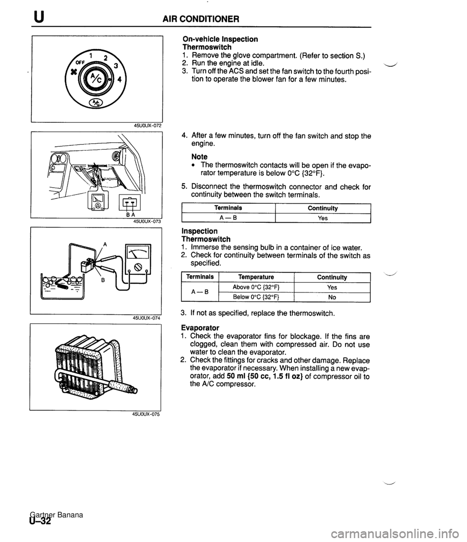
AIR CONDITIONER On-vehicle Inspection Thermoswitch 1. Remove the glove compartment. (Refer to section S.) 2. Run the engine at idle. u 3. Turn off the ACS and set the fan switch to the fourth posi- tion to operate the blower fan for a few minutes. 4. After a few minutes, turn off the fan switch and stop the engine. Note The thermoswitch contacts will be open if the evapo- rator temperature is below 0°C (32°F). 5. Disconnect the thermoswitch connector and check for continuity between the switch terminals. I Terminals I Continuity I I A-B I Yes I - -- Inspection Thermoswitch 1. Immerse the sensing bulb in a container of ice water. 2. Check for continuity between terminals of the switch as specified. 3. If not as specified, replace the thermoswitch. Continuity ( Terminals I Temperature A-B Evaporator 1. Check the evaporator fins for blockage. If the fins are clogged, clean them with compressed air. Do not use water to clean the evaporator. 2. Check the fittings for cracks and other damage. Replace the evaporator if necessary. When installing a new evap- orator, add 50 ml (50 cc, 1.5 fl oz) of compressor oil to the A/C compressor. d Above 0°C {32OFj Below 0°C (32°F) Yes No Gartner Banana
Page 1096 of 1708
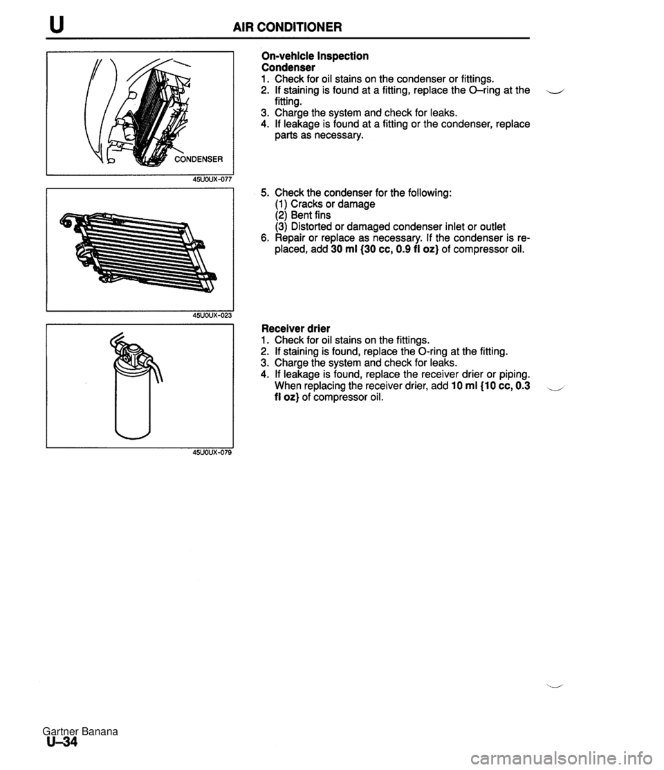
u AIR CONDITIONER On-vehicle Inspection Condenser 1. Check for oil stains on the condenser or fittings. 2. If staining is found at a fitting, replace the O-ring at the u fitting. 3. Charge the system and check for leaks. 4. If leakage is found at a fitting or the condenser, replace parts as necessary. 5. Check the condenser for the following: (1) Cracks or damage (2) Bent fins (3) Distorted or damaged condenser inlet or outlet 6. Repair or replace as necessary. If the condenser is re- placed, add 30 ml(30 cc, 0.9 fi oz} of compressor oil. Receiver drier 1. Check for oil stains on the fittings. 2. If staining is found, replace the O-ring at the fitting. 3. Charge the system and check for leaks. 4. If leakage is found, replace the receiver drier or piping. When replacing the receiver drier, add 10 ml I10 cc, 0.3 -, fl or) of compressor oil. Gartner Banana