warning MAZDA MX-5 1994 Repair Manual
[x] Cancel search | Manufacturer: MAZDA, Model Year: 1994, Model line: MX-5, Model: MAZDA MX-5 1994Pages: 1708, PDF Size: 82.34 MB
Page 447 of 1708
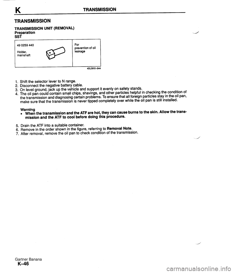
TRANSMISSION TRANSMISSION UNIT (REMOVAL) Preparation SST 49 0259 440 Holder, mainshaft For prevention of oil leakage 1. Shift the selector lever to N range. 2. Disconnect the negative battery cable. 3. On level ground, jack up the vehicle and support it evenly on safety stands. 4. The oil pan could contain small chips, shavings, and other particles helpful in checking the condition of the transmission and diagnosing certain problems. To ensure that all foreign particles stay in the oil pan, make sure that the transmission is never tipped completely over while the oil pan is still installed. Warning When the transmission and the ATF are hot, they can cause burns to the skin. Allow the trans- mission and the ATF to cool before doing this procedure. 5. Drain the ATF into a suitable container. 6. Remove in the order shown in the figure, referring to Removal Note. 7. After removal, remove the oil pan to check condition of the transmission. Gartner Banana
Page 451 of 1708
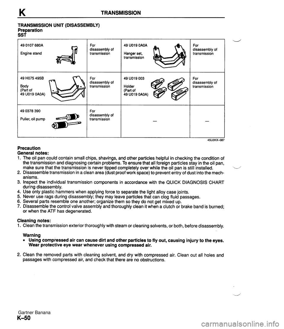
TRANSMISSION TRANSMISSION UNIT (DISASSEMBLY) Preparation SST 49 H075 4958 Body (Part of 49 U019 OAOA) For disassembly of transmission For disassembly of transmission For disassembly of transmission 49 U019 OAOA Hanger set, transmission 49 U019 003 Holder (Part of 49 U019 OAOA) For disassembly of transmission For disassembly of transmission Precaution General notes: 1. The oil pan could contain small chips, shavings, and other particles helpful in checking the condition of the transmission and diagnosing certain problems. To ensure that all foreign particles stay in the oil pan, make sure that the transmission is never tipped completely over while the oil pan is still installed. L/ 2. Disassemble transmission in a clean area (dust proof work space) to prevent entry of dust into the mech- anisms. 3. Inspect the individual transmission components in accordance with the QUICK DIAGNOSIS CHART during disassembly. 4. Use only plastic hammers when applying force to separate the light alloy case joints. 5. Never use rags during disassembly; they may leave particles that can clog fluid passages. 6. Several parts resemble one another; organize them so they do not get mixed up. 7. Disassemble the control valve assembly and thoroughly clean it when a clutch or brake band is burned; or when the ATF has degenerated. Cleaning notes: 1. Clean the transmission exterior thoroughly with steam or cleaning solvents, or both, before disassembly. Warning Using compressed air can cause dirt and other particles to fly out, causing injury to the eyes. Wear protective eye wear whenever using compressed air. 2. Clean the removed parts with cleaning solvent, and dry with compressed air. Clean out all holes and passages with compressed air, and check that there are no obstructions. Gartner Banana
Page 513 of 1708
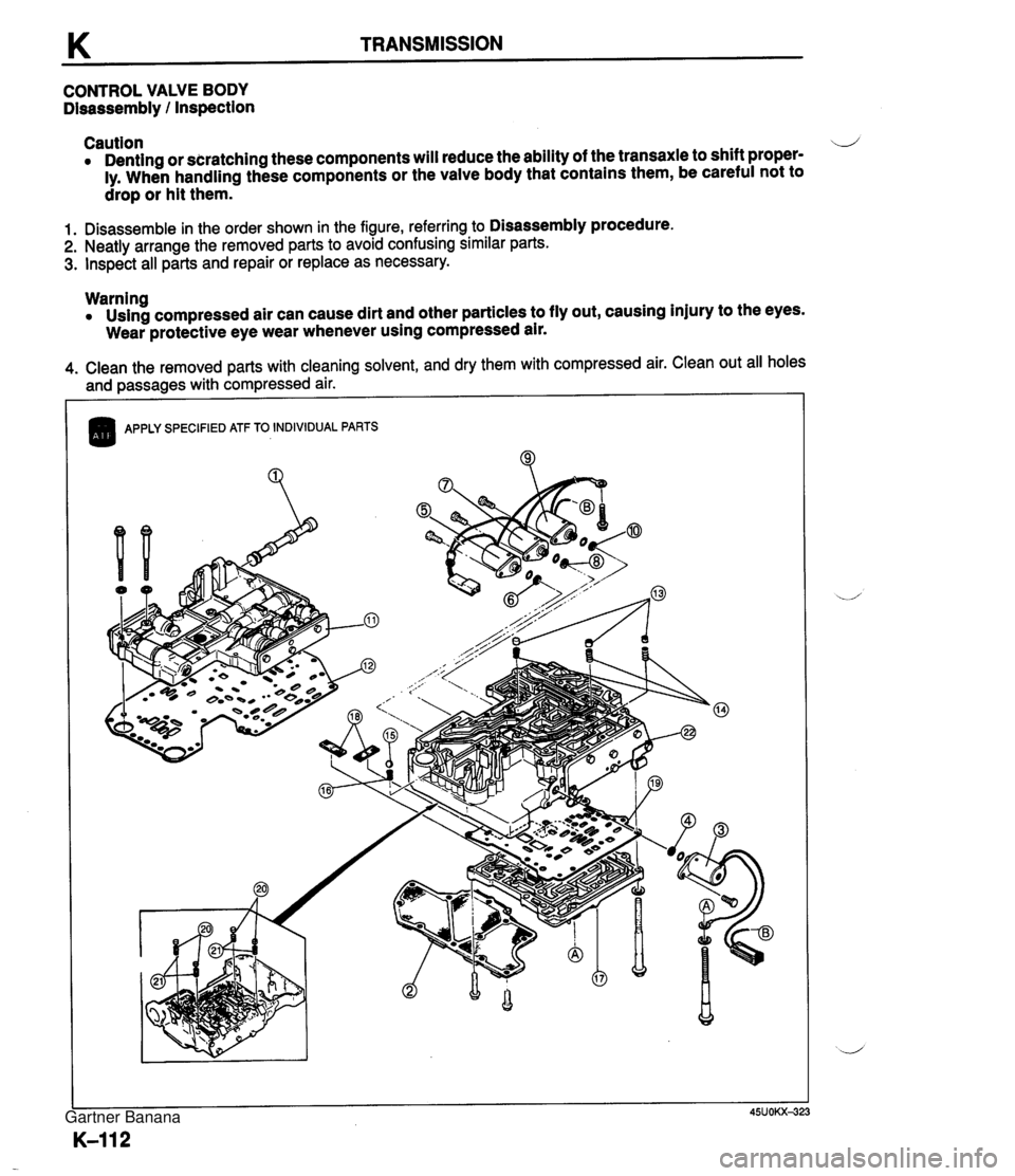
K TRANSMISSION CONTROL VALVE BODY Disassembly / Inspection Caution 4 Denting or scratching these components will reduce the ability of the transaxle to shift proper- ly. When handling these components or the valve body that contains them, be careful not to drop or hit them. 1. Disassemble in the order shown in the figure, referring to Disassembly procedure. 2. Neatly arrange the removed parts to avoid confusing similar parts. 3. Inspect all parts and repair or replace as necessary. Warning Using compressed air can cause dirt and other particles to fly out, causing injury to the eyes. Wear protective eye wear whenever using compressed air. 4. Clean the removed parts with cleaning solvent, and dry them with compressed air. Clean out all holes and passages with compressed air. I ( APPLY SPECIFIED ATF TO INDIVIDUAL PARTS Gartner Banana
Page 517 of 1708
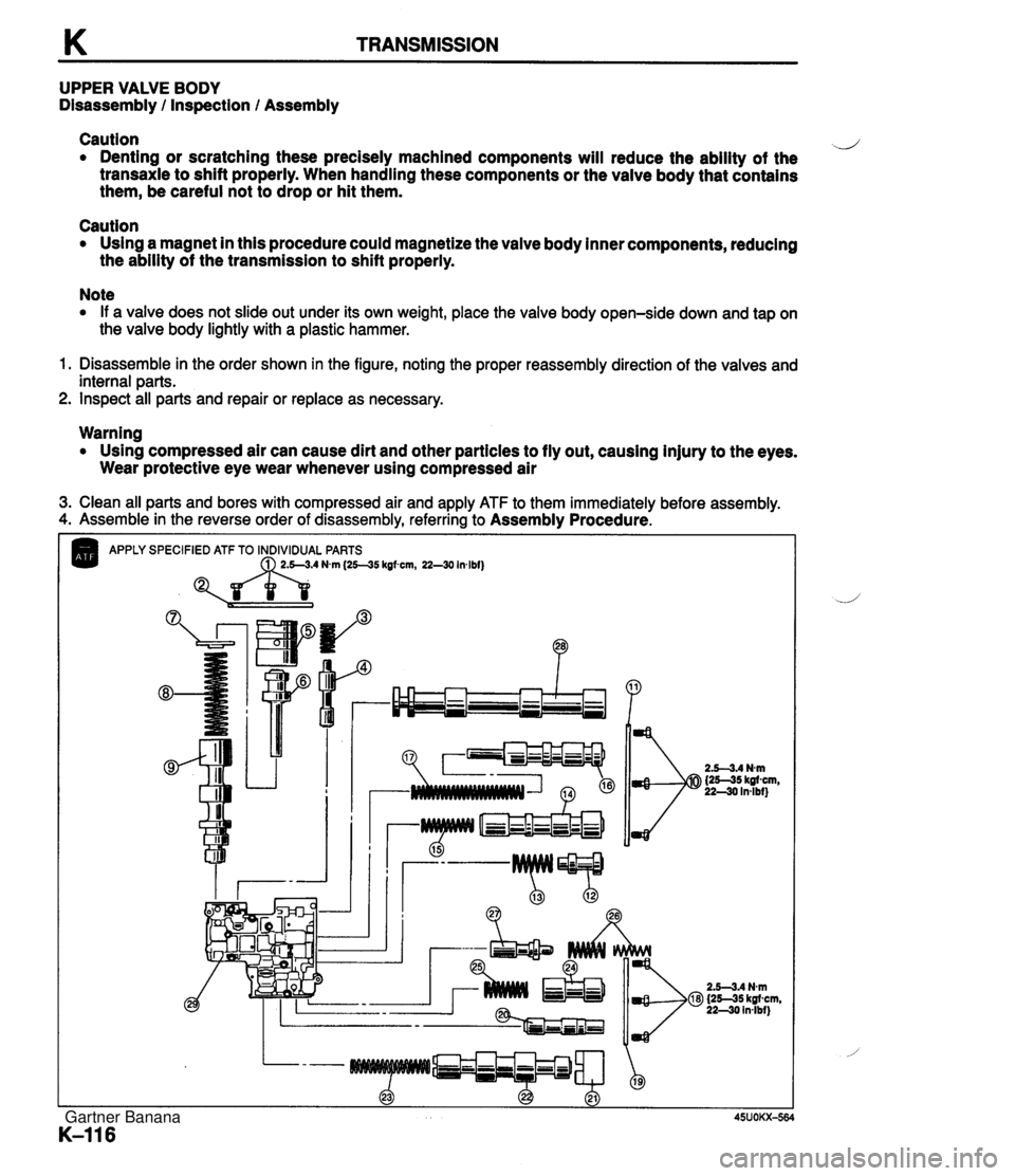
K TRANSMISSION UPPER VALVE BODY Disassembly / Inspection / Assembly Caution d Denting or scratching these precisely machined components will reduce the ability of the transaxle to shift properly. When handling these components or the valve body that contains them, be careful not to drop or hit them. Caution Using a magnet in this procedure could magnetize the valve body inner components, reducing the ability of the transmission to shift properly. Note If a valve does not slide out under its own weight, place the valve body open-side down and tap on the valve body lightly with a plastic hammer. 1. Disassemble in the order shown in the figure, noting the proper reassembly direction of the valves and internal parts. 2. Inspect all parts and repair or replace as necessary. Warning Using compressed air can cause dirt and other particles to fly out, causing injury to the eyes. Wear protective eye wear whenever using compressed air 3. Clean all parts and bores with compressed air and apply ATF to them immediately before assembly. 4. Assemble in the reverse order of disassembly, referring to Assembly Procedure. APPLY SPECIFIED ATF TO INDIVIDUAL PARTS Nvn (25--35 kgfwn, 22-30 Inlbf) Gartner Banana
Page 521 of 1708
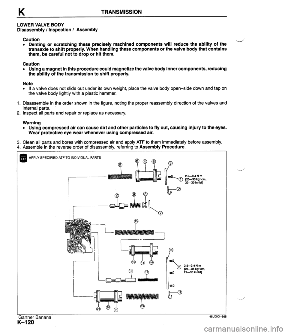
K TRANSMISSION LOWER VALVE BODY Disassembly l Inspection l Assembly Caution d Denting or scratching these precisely machined components will reduce the ability of the transaxle to shift properly. When handling these components or the valve body that contains them, be careful not to drop or hit them. Caution Using a magnet in this procedure could magnetize the valve body inner components, reducing the ability of the transmission to shift properly. Note If a valve does not slide out under its own weight, place the valve body open-side down and tap on the valve body lightly with a plastic hammer. 1. Disassemble in the order shown in the figure, noting the proper reassembly direction of the valves and internal parts. 2. Inspect all parts and repair or replace as necessary. Warning Using compressed air can cause dirt and other particles to fly out, causing injury to the eyes. Wear protective eye wear whenever using compressed air. 3. Clean all parts and bores with compressed air and apply ATF to them immediately before assembly. 4. Assemble in the reverse order of disassembly, referring to Assembly Procedure. APPLY SPECIFIED ATF TO INDIVIDUAL PARTS B ?? "P 2.5-3.4 Nm {25-35 kgfcm, 22-30 in4bf) Gartner Banana
Page 529 of 1708

K TRANSMISSION On-vehicle Removal 1. Disconnect the negative battery cable. 2. On level ground, jack up the vehicle and support it evenly on safety stands. w 3. Remove the exhaust pipe. (Refer to page K-45.) Warning When the transmission and the ATF are hot, they can cause burns to the skin. Allow the transmis- sion and the ATF to cool before doing this proce- dure. 4. Loosen the oil pan installation bolts, and drain the ATF into a container. 5. Disconnect the vacuum hose. 6. Remove the vacuum diaphragm, O-rings, and vacuum diaphragm rod. 7. Remove the oil pan, and the gasket. 8. Disconnect the solenoid valve connector. 9. Remove the harness from the bracket. 10. Remove the control valve body assembly. Gartner Banana
Page 531 of 1708

K TRANSMISSION VACUUM DIAPHRAGM Preparation SST Note Excessive shift shock and improper shifting often indicate a vacuum diaphragm malfunction. 49 GO32 355 Adjustment gauge Warning When the transmission and the ATF are hot, they can cause burns to the skin. Allow the trans- mission and the ATF to cool before doing this procedure. For adjustment of vacuum diaphragm rod On-vehicle Removal 1. On level ground, jack up the vehicle and support it evenly on safety stands. 2. Remove the exhaust pipe. (Refer to page K-45.) 3. Loosen the oil pan mounting bolts, and drain approx. 1.0 L (1.1 US qt, 0.9 Imp qt) of ATF. L' 4. Disconnect the vacuum hose. 5. Remove the vacuum diaphragm, O-rings, and vacuum diaphragm rod. Inspection 1. Check that the vacuum diaphragm rod moves when vac- uum is applied to the vacuum diaphragm. 2. If not correct, replace the vacuum diaphragm. Gartner Banana
Page 586 of 1708
Before beginning any service procedure. refer to section T of this manual for air bag system service warnings and audio antitheft system alarm conditions . FRONT AND REAR AXLES ....................................... INDEX M- 2 ..................................... OUTLINE M- 3 SPECIFICATIONS ........................... M- 3 TROUBLESHOOTING GUIDE .................. M- 4 ............................... FRONT AXLE M- 4 ................................ REAR AXLE M- 4 ............................. DIFFERENTIAL M- 4 ................................. FRONT AXLE M- 5 PREPARATION ............................. M- 5 WHEEL HUB. STEERING KNUCKLE .......... M- 6 .................................. REAR AXLE M-10 PREPARATION ............................. M-10 ......................... DISC BRAKE TYPE M-11 ................................ DRIVE SHAFT M-17 .................... DOUBLE OFFSET JOINT M-17 ............................... DIFFERENTIAL M-23 PREPARATION ............................. M-23 DIFFERENTIAL OIL ......................... M-25 ................. OIL SEAL (OUTPUT SHAFT) M-25 DIFFERENTIAL. STANDARD; DIFFERENTIAL. TORQUE SENSING LIMITED SLIP ("TORSEN" LSD) ........................... M-27 45UOMX-001 "TORSEN" is a registered trademark of ZEXEL-GLEASON USA . INC Gartner Banana
Page 628 of 1708

Before beginning any service procedure. refer to section T of this manual for I air bag system service warnings and audio antitheft system alarm conditions . STEERING SYSTEM INDEX ....................................... N- 2 OUTLINE ..................................... N- 4 SPECIFICATIONS ........................... N- 4 MANUAL STEERING .......................... N- 4 PREPARATION ............................. N- 4 ................ TROUBLESHOOTING GUIDE N- 5 BOOT ...................................... N- 6 STEERING WHEEL AND COLUMN ........... N- 8 ............. STEERING GEAR AND LINKAGE N-12 ENGINE SPEED SENSING POWER STEERING .......................... N-18 PREPARATION ............................. N-18 TROUBLESHOOTING GUIDE ................ N-20 AIR BLEEDING ............................. N-21 POWER STEERING FLUID ................... N-22 STEERING WHEEL AND COLUMN ........... N-24 STEERING GEAR AND LINKAGE ............. N-25 POWER STEERING OIL PUMP ............... N-33 DRIVE BELT ................................ N-37 25UONX-001 Gartner Banana
Page 666 of 1708

Before beginning any service procedure. refer to section T of this manual for air bag system service warnings and audio antitheft system alarm conditions . BRAKING SYSTEM INDEX ....................................... P- 2 OUTLINE ..................................... P- 4 SPEClFlCATlONS ........................... P- 4 BRAKE SYSTEM ............................. P- 5 PREPARATION ............................. P- 5 TROUBLESHOOTING GUIDE ................ P- 6 AIR BLEEDING ............................. P- 7 BRAKE HYDRAULIC LINE ................... P- 7 BRAKE FLUID .............................. P- 8 ............................. BRAKE PEDAL P- 9 MASTER CYLINDER (STANDARD) ............ P-11 MASTER CYLINDER (ABS) .................. P-14 POWER BRAKE UNIT ....................... P-20 PROPORTIONING BYPASS VALVE ........... P-23 FRONT BRAKE (DISC) ...................... P-25 CALIPER ................................... P-28 REAR BRAKE (DISC) ........................ P-29 CALIPER ................................... P-32 PARKING BRAKE SYSTEM .................... P-34 TROUBLESHOOTING GUIDE ................ P-34 PARKING BRAKE LEVER .................... P-34 PARKING BRAKE CABLE .................... P-36 ANTILOCK BRAKE SYSTEM (ABS) ............ P-37 DESCRIPTION .............................. P-37 PREPARATION ............................. P-37 TROUBLESHOOTING GUIDE ................ P-38 CIRCUIT DIAGRAM ......................... P-52 HYDRAULIC UNIT ........................... P-53 ........................ ABS CONTROL UNIT P-55 RELAYS .................................... P-56 ABS WHEEL SPEED SENSOR (FRONT) ....... P-58 ABS SENSOR ROTOR (FRONT) .............. P-59 ABS WHEEL SPEED SENSOR (REAR) ........ P-60 ABS SENSOR ROTOR (REAR) ............... P-61 25UOPX-001 Gartner Banana