warning MAZDA MX-5 1994 Service Manual
[x] Cancel search | Manufacturer: MAZDA, Model Year: 1994, Model line: MX-5, Model: MAZDA MX-5 1994Pages: 1708, PDF Size: 82.34 MB
Page 316 of 1708

CHARGING SYSTEM G Battery discharge test capable of reading 0.01V Quick charge for 30 min- utes and recheck voltage elo ow 12.4V Above 12.4V I Replace battery el c Apply test load (see test load chart) to the battery using a battery load tester Record battery positive voltage at the end of 15 seconds; is voltage more than specifica- tion? I Measure open circuit voltage of battery 1 Replace battery I I Below 12.4V Abov'e 12.4V Test load I Battew I Load (A1 I Battery posltive voltage with load I Charge battery ( I Battery OK I Terminal and cable 1. Clean and tighten the battery terminals and cables. 2. Coat the terminals with arease. 3. Inspect for corroded or 6ayed battery cables. 4. Check the rubber protector on the positive terminal for proper coverage. Recharging Warning Before performing maintenance or recharging the battery, turn off all accessories and stop the engine. The negative battery cable must be removed first and installed last. Battery S46A24L(S) Caution Do not remove vent caps. Follow carefully the instructions of the battery charger to prevent overcharging. u Do not recharging over 30 minutes to prevent damage the battery. Slow charge (A) Under 3 - -- Quick charge (A) Max. 20 Gartner Banana
Page 324 of 1708
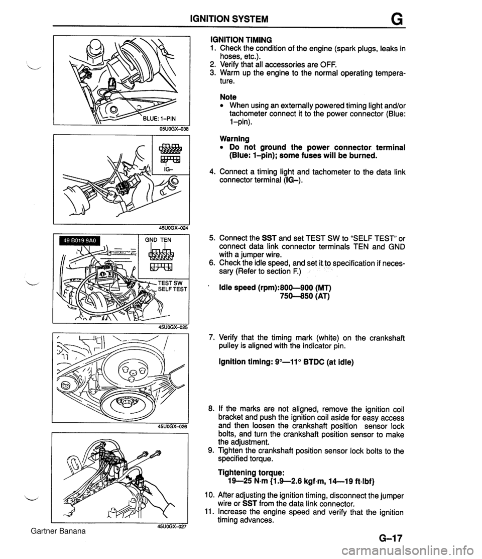
IGNITION SYSTEM G GND TEN I I I IGNITION TIMING 1. Check the condition of the engine (spark plugs, leaks in hoses, etc.). 2. Verify that all accessories are OFF. 3. Warm up the engine to the normal operating tempera- ture. Note When using an externally powered timing light and/or tachometer connect it to the power connector (Blue: l-pin). Warning Do not ground the power connector. terminal (Blue: l-pin); some fuses will be burned. 4. Connect a timing light and tachometer to the data link connector terminal (IG-). 5. Connect the SST and set TEST SW to "SELF TEST" or connect data link connector terminals TEN and GND with a jumper wire. 6. Check the idle speed, and set it to specification if neces- sary (Refer to section F.) ' Idle speed (rpm):800-900 (MT) 75-50 (AT) 7. Verify that the timing mark (white) on the crankshaft pulley is aligned with the indicator pin. Ignition timing: 9"-11" BTDC (at idle) 8. If the marks are not aligned, remove the ignition coil bracket and push the ignition coil aside for easy access and then loosen the crankshaft position sensor lock bolts, and turn the crankshaft position sensor to make the adjustment. 9. Tighten the crankshaft position sensor lock bolts to the specified torque. Tightening torque: 19-25 N-m (1 3-2.6 kgf~m, l4--19 ft.lbf) 10. After adjusting the ignition timing, disconnect the jumper wire or SST from the data link connector. 11. Increase the engine speed and verify that the ignition timing advances. Gartner Banana
Page 345 of 1708
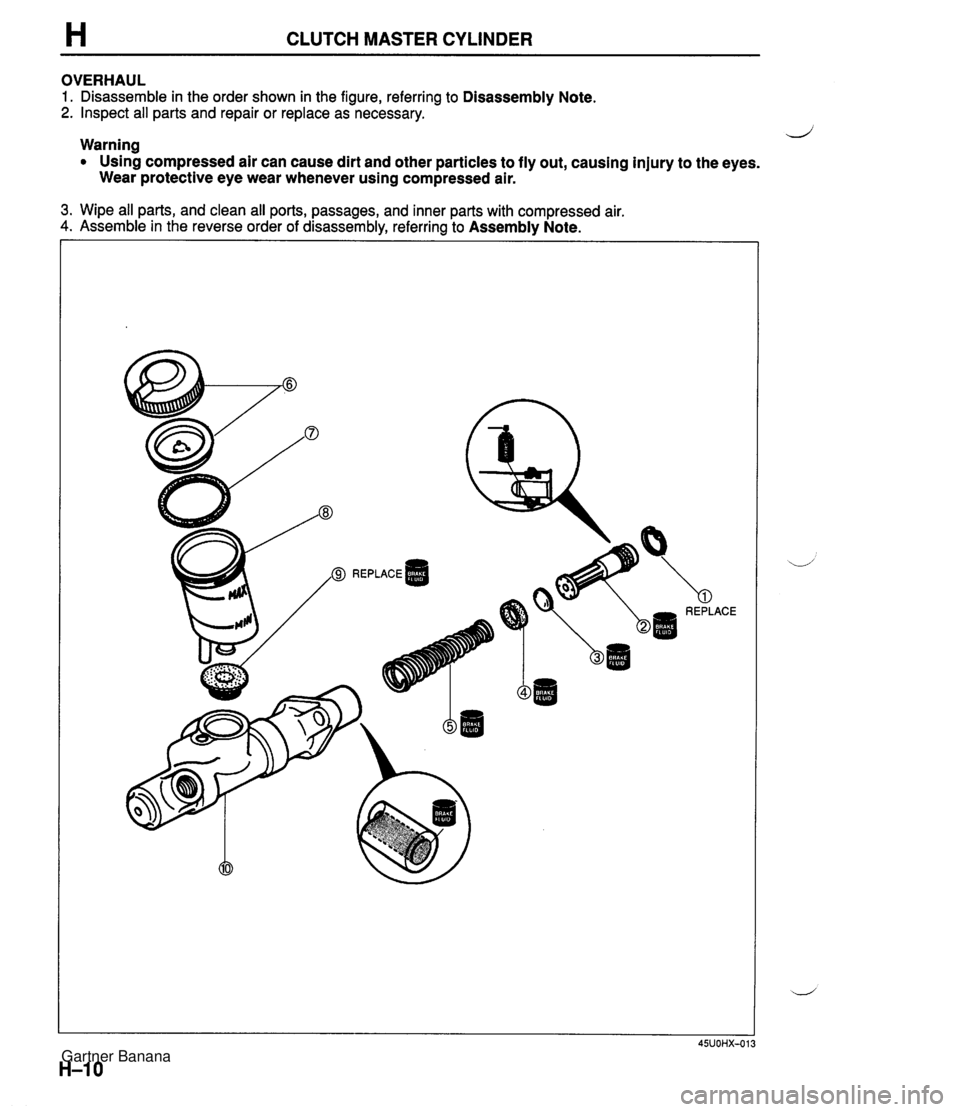
H CLUTCH MASTER CYLINDER OVERHAUL 1. Disassemble in the order shown in the figure, referring to Disassembly Note. 2. Inspect all parts and repair or replace as necessary. Warning d Using compressed air can cause dirt and other particles to fly out, causing injury to the eyes. Wear protective eye wear whenever using compressed air. 3. Wipe all parts, and clean all ports, passages, and inner parts with compressed air. 4. Assemble in the reverse order of disassembly, referring to Assembly Note. 'a REPLACE Gartner Banana
Page 346 of 1708
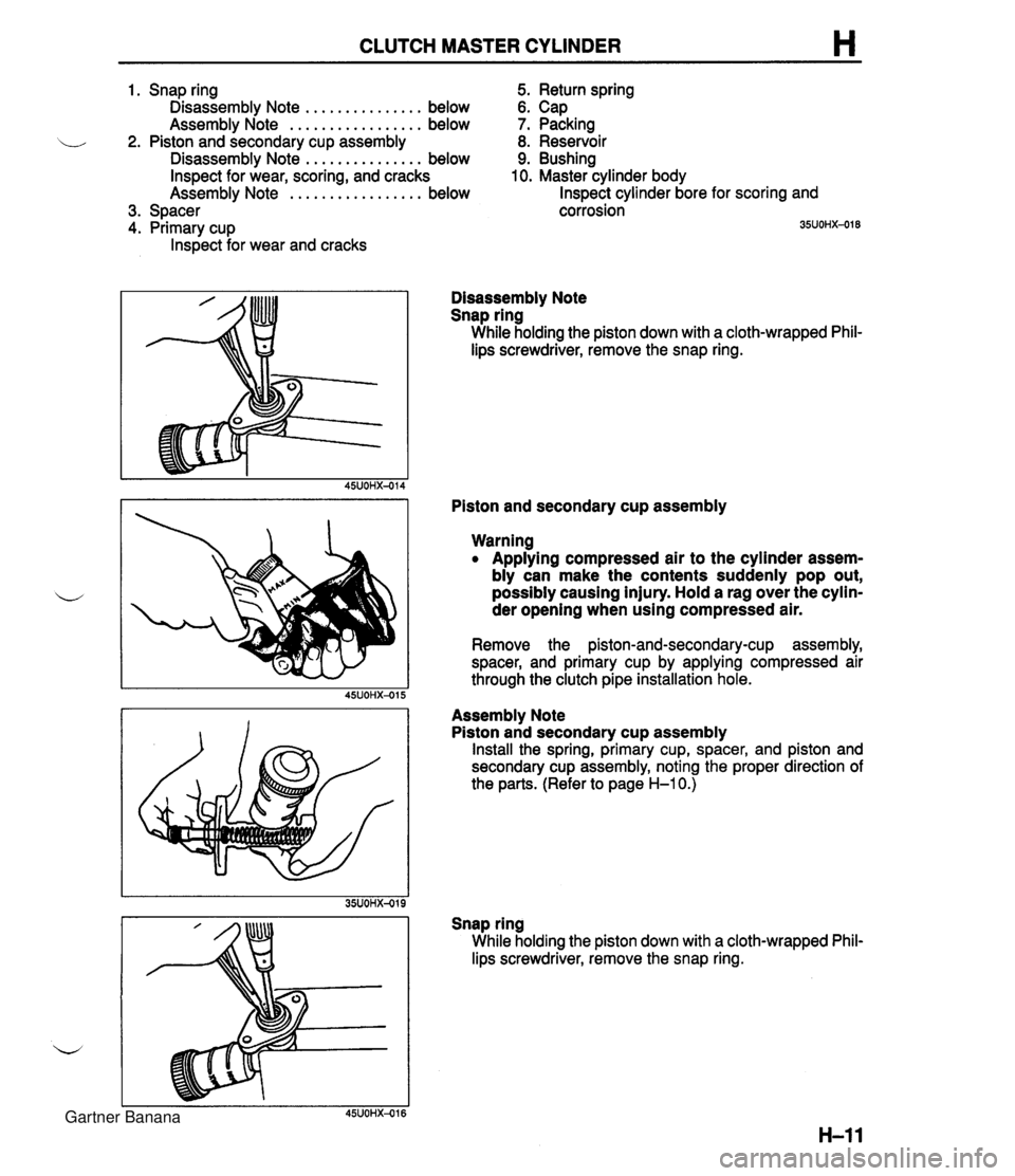
CLUTCH MASTER CYLINDER H 1. Snap ring 5. Return spring Disassembly Note ............... below 6. Cap Assembly Note ................. below 7. Packing 2. Piston and secondary cup assembly 8. Reservoir Disassembly Note ............... below 9. Bushing Inspect for wear, scoring, and cracks 10. Master cylinder body Assemblv Note ................. below Inspect cylinder bore for scoring and 3. Spacer 4. Primary cup lnspect for wear and cracks corrosion 35UOHX-018 Disassembly Note Snap ring While holding the piston down with a cloth-wrapped Phil- lips screwdriver, remove the snap ring. Piston and secondary cup assembly Warning Applying compressed air to the cylinder assem- bly can make the contents suddenly pop out, possibly causing injury. Hold a rag over the cylin- der opening when using compressed air. Remove the piston-and-secondary-cup assembly, spacer, and primary cup by applying compressed air through the clutch pipe installation hole. Assembly Note Piston and secondary cup assembly Install the spring, primary cup, spacer, and piston and secondary cup assembly, noting the proper direction of the parts. (Refer to page H-1 0.) Snap ring While holding the piston down with a cloth-wrapped Phil- lips screwdriver, remove the snap ring. Gartner Banana
Page 348 of 1708

CLUTCH RELEASE CYLINDER H Installation Note Clutch pipe 1. Modify the clutch pipe tightening torque to allow for use of a torque wrench-SST combination. (Refer to section GI "Torque Formulas".) 2. Tighten the clutch pipe by using the SST. Tightening torque: 12.8-21.5 N-m (1 30-220 kgfam, 11%-190 in-lbf) Air Bleeding After installation, bleed the clutch system. (Refer to page H-9.) OVERHAUL 1. Disassemble in the order shown in the figure, referring to Disassembly Note. 2. lnspect all parts and repair or replace as necessary. Warning Using compressed air can cause dirt and other particles to fly out, causing injury to the eyes. Wear protective eye wear whenever using compressed air. 3. Wipe all parts, and clean all ports, passages, and inner parts with compressed air. 4. Assemble in the reverse order of disassembly. 1. Boot 5. Bleeder cap 2. Push rod 6. Bleeder screw 3. Piston and cup assembly 7. Steel ball Disassembly Note . . . . . . . . . . . . . . . below 8. Release cylinder body Inspect for wear, scoring, and cracks Inspect cylinder bore for scoring and corro- 4. Spring sion Disassembly Note Piston and cup assembly Warning Applying compressed air to the cylinder assem- bly can make the contents suddenly pop out, possibly causing injury. Hold a rag over the cylin- der opening when using compressed air. Remove the piston-and-cup assembly by applying com- pressed air through the clutch pipe installation hole. Gartner Banana
Page 355 of 1708

Before beginning any service procedure. refer to section T of this manual for air bag system service warnings and audio antitheft system alarm conditions . MANUAL TRANSMISSION INDEX ....................................... J- 2 ..................................... OUTLINE J- 3 SPECIFICATIONS ........................... J- 3 ........................ STRUCTURAL VIEW J- 4 ............................. COMPONENTS J- 5 ............................. POWER FLOW J- 6 TROUBLESHOOTING GUIDE .................. J- 7 .......................... TRANSMISSION OIL J- 8 ............................... INSPECTION J- 8 ............................ REPLACEMENT J- 8 TRANSMISSION .............................. J- 9 ............................. PREPARATION J- 9 REMOVAL .................................. J-10 DISASSEMBLY ............................. J-13 ............................... INSPECTION 5-23 ASSEMBLY ................................. J-26 INSTALLATION ............................. J-45 25UOJX-011 Gartner Banana
Page 367 of 1708
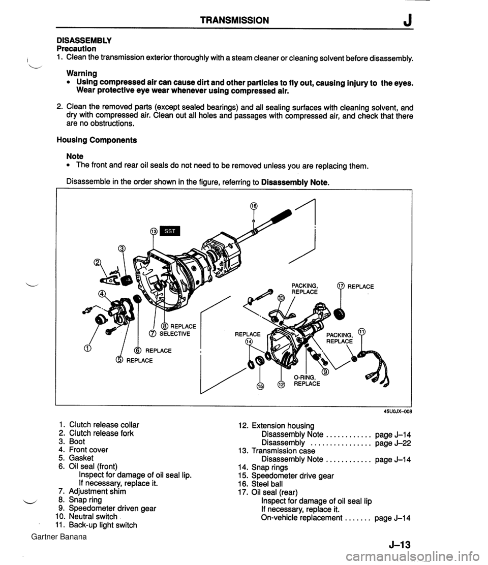
TRANSMISSION J DISASSEMBLY Precaution : 1. Clean the transmission exterior thoroughly with a steam cleaner or cleaning solvent before disassembly. b Warning Using compressed air can cause dirt and other particles to fly out, causing injury to the eyes. Wear protective eye wear whenever using compressed air. 2. Clean the removed parts (except sealed bearings) and all sealing surfaces with cleaning solvent, and dry with compressed air. Clean out all holes and passages with compressed air, and check that there are no obstructions. Housing Components Note The front and rear oil seals do not need to be removed unless you are replacing them. Disassemble in the order shown in the figure, referring to Disassembly Note. 1. Clutch release collar 2. Clutch release fork 3. Boot 4. Front cover 12. Extension housing Disassembly Note ............ page J-14 Disassembly ................ page J-22 13. Transmission case 5. Gasket Disassembly Note ............ pane J-14 6. Oil seal (front) lnspect for damage of oil seal lip. If necessary, replace it. 7. Adjustment shim 8. Snap ring 9. Speedometer driven gear 10. Neutral switch 11. Back-up light switch . - 14. Snap rings 15. Speedometer drive gear 16. Steel ball 17. Oil seal (rear) lnspect for damage of oil seal lip If necessary, replace it. On-vehicle replacement ....... page J-14 Gartner Banana
Page 402 of 1708

Before beginning any service procedure. refer to section T of this manual for air bag system service warnings and audio antitheft system alarm conditions . AUTOMATIC TRANSMISSION INDEX ................................ K- 2 OUTLINE ............................. K- 3 SPECIFICATIONS ................... K- 3 ........... CROSS-SECTIONAL VIEW K- 4 POWER FLOW DIAGRAM ............ K- 5 OPERATION OF COMPONENTS ...... K- 5 FLUID PASSAGE LOCATIONS ........ K- 6 TROUBLESHOOTING .................. K- 8 GENERAL NOTES ................... K- 8 .......... QUICK DIAGNOSIS CHART K- 9 ON-BOARD DIAGNOSIS SYSTEM ...... K- 11 DESCRIPTION ...................... K- 11 PREPARATION ...................... K- 11 ....... DIAGNOSTIC TROUBLE CODE K- 11 .......... MECHANICAL SYSTEM TEST K- 22 PREPARATION ...................... K- 22 STALL TEST ........................ K- 22 TIME LAG TEST ..................... K- 25 LINE PRESSURE TEST .............. K- 26 ROAD TEST .......................... K- 29 D-RANGE TEST ..................... K- 29 S-RANGE TEST ..................... K- 31 ..................... L-RANGE TEST K- 32 . P-RANGE TEST ..................... K- 33 AUTOMATIC TRANSMISSION FLUID (ATF) ................................ K- 35 ATF ................................ K- 35 REPLACEMENT ..................... K- 37 ELECTRICAL SYSTEM COMPONENTS . . K- 38 PREPARATION ...................... K- 38 HOLD SWITCH ...................... K- 38 PARWNEUTRAL SWITCH ............ K- 39 .............. ATF THERMOSENSOR K- 41 VEHICLE SPEED PULSE GENERATOR ...................... K- 41 1-2 SHIFT. 2-3 SHIFT. 3-4 SHIFT. ... 3-2 CONTROL SOLENOID VALVE K- 42 LOCKUP CONTROL SOLENOID ....... VALVE ............................ K- 42 POWERTRAIN CONTROL MODULE (TRANSMISSION) .................. K- 43 TRANSMISSION ....................... K- 46 TRANSMISSION UNIT (REMOVAL) .... K- 46 TRANSMISSION UNlT (DISASSEMBLY) ................... K- 50 TORQUE CONVERTER .............. K- 61 OILPUMP .......................... K- 62 FOURTH GEAR CONNECTING SHELL AND FOURTH GEAR PLANETARY GEAR UNIT (FOURTH GEAR SUN GEAR. FOURTH GEAR PLANETARY PINION CARRIER. FOURTH GEAR CLUTCH HUB) ...... K- 67 DIRECT CLUTCH .................... K- 70 FOURTH GEAR BAND SERVO ........ K- 76 DRUM SUPPORT. ACCUMULATOR. AND FOURTH GEAR CASE ......... K- 79 2ND BAND SERVO .................. K- 83 FRONT CLUTCH .................... K- 86 REAR CLUTCH ...................... K- 91 CONNECTING SHELL AND FRONT PLANETARY GEAR UNlT (REAR CLUTCH HUB. FRONT PLANETARY PINION CARRIER. REAR SUN GEAR) ................. K- 96 REAR PLANETARY GEAR UNlT (CONNECTING DRUM. REAR PLANETARY PINION CARRIER. ONE-WAY CLUTCH) K- 98 LOW AND REVERSE BRAKE K-102 ................ ......... EXTENSION HOUSING AND PARKING MECHANISM ............. K-107 OIL SEAL ........................... K-ill CONTROL VALVE BODY ............. K-112 UPPER VALVE BODY ................ K-116 LOWER VALVE BODY ............... K-120 CONTROL VALVE BODY ............. K-125 VACUUM DIAPHRAGM ............... K-130 TRANSMISSION UNIT (ASSEMBLY) ... K-132 TRANSMISSION UNIT (INSTALLATION) ................... K-147 OIL COOLER .......................... K-151 REMOVAL I INSPECTION I INSTALLATION ..................... K-151 DRIVE PLATE ......................... K-152 PREPARATION ...................... K-152 REMOVAL 1 INSPECTION I INSTALLATION ..................... K-152 SHIFT MECHANISM (WITH SHIFT-LOCK SYSTEM) ......... K-154 SHIFT-LOCK SYSTEM COMPONENTS K-154 TROUBLESHOOTING ................ K-155 SHIFT-LOCK ........................ K-157 EMERGENCY OVERRIDE BUTTON ... K-157 KEY INTERLOCK .................... K-157 KEY INTERLOCK SOLENOID ......... K-157 KEY INTERLOCK UNIT ............... K-158 P RANGE SWITCH .................. K-159 SHIFT-LOCKACTUATOR ............. K-159 SELECTOR LEVER .................. K-161 HYDRAULIC CIRCUIT .................. K-168 P RANGE ........................... K-168 R RANGE ........................... K-169 N RANGE; BELOW 7 kmlh I4.34 mph) . K-170 N RANGE; ABOVE 9 kmlh (5.58 mph} . K-171 D RANGE; 1 ST GEAR ................ K-172 D RANGE; 2ND GEAR ............... K-173 D RANGE; THIRD GEAR ............. K-174 D RANGE; FOURTH GEAR. LOCKUP ON ....................... K-175 S RANGE; 1 ST GEAR ................ K-176 S RANGE; 2ND GEAR ............... K-177 S RANGE; THIRD GEAR ............. K-178 L RANGE; 1 ST GEAR ................ K-179 L RANGE; 2ND GEAR ................ K-180 Gartner Banana
Page 427 of 1708
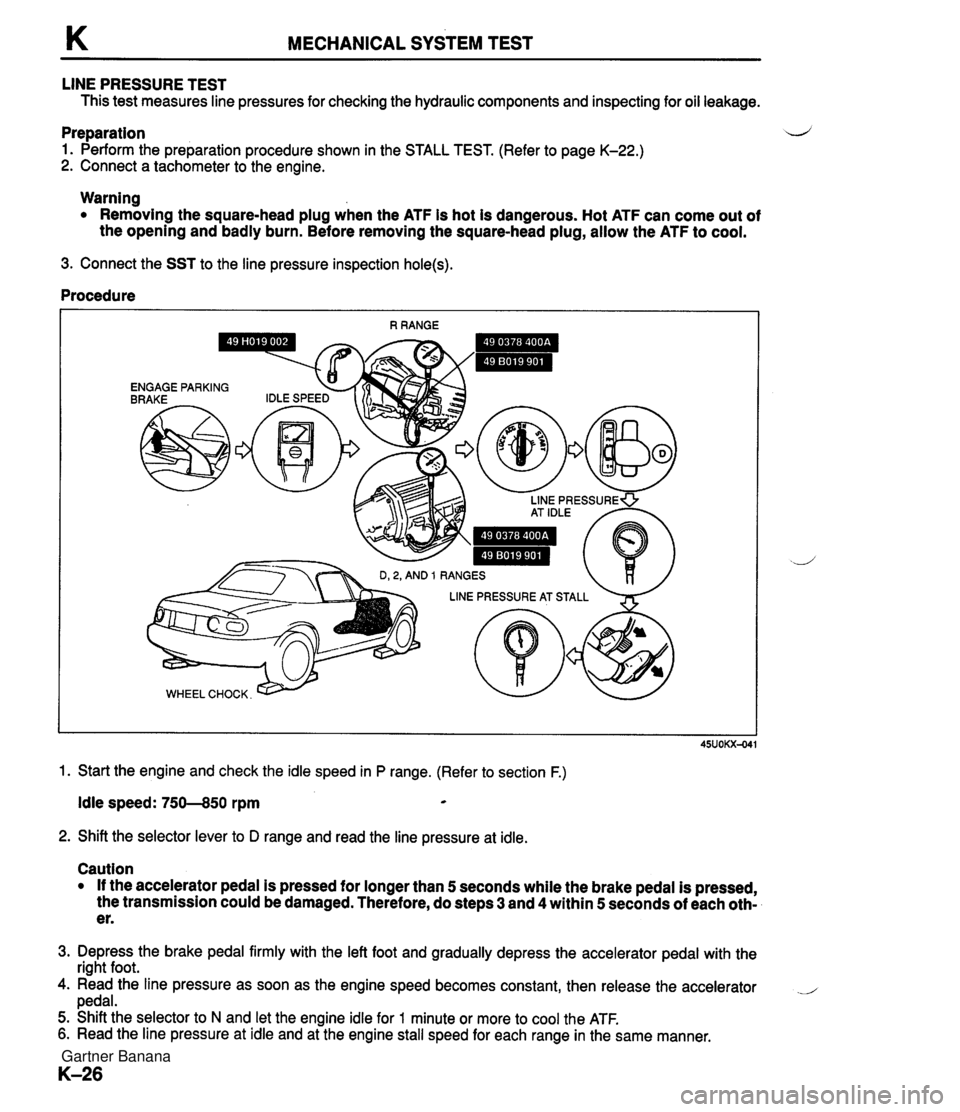
K MECHANICAL SYSTEM TEST LINE PRESSURE TEST This test measures line pressures for checking the hydraulic components and inspecting for oil leakage. Preparation d 1. Perform the preparation procedure shown in the STALL TEST. (Refer to page K-22.) 2. Connect a tachometer to the engine. Warning Removing the square-head plug when the ATF is hot is dangerous. Hot ATF can come out of the opening and badly burn. Before removing the square-head plug, allow the ATF to cool. 3. Connect the SST to the line pressure inspection hole(s). Procedure 1. Start the engine and check the idle speed in P range. (Refer to section F.) Idle speed: 750--850 rpm * 2. Shift the selector lever to D range and read the line pressure at idle. Caution If the accelerator pedal is pressed for longer than 5 seconds while the brake pedal is pressed, the transmission could be damaged. Therefore, do steps 3 and 4 within 5 seconds of each oth- er. 3. Depress the brake pedal firmly with the left foot and gradually depress the accelerator pedal with the right foot. 4. Read the line pressure as soon as the engine speed becomes constant, then release the accelerator .- pedal. 5. Shift the selector to N and let the engine idle for 1 minute or more to cool the ATF. 6. Read the line pressure at idle and at the engine stall speed for each range in the same manner. Gartner Banana
Page 438 of 1708

AUTOMATIC TRANSMISSION FLUID (ATF) K REPLACEMENT 1. On level ground, jack up the vehicle and support it evenly on safety stands. Warning When the transmission and the ATF are hot, they can cause burns to the skin. Allow the transmis- sion and the ATF to cool before doing this proce- dure. 2. Loosen the oil pan installation bolts, and drain the ATF into a container. 3. Remove the oil pan and gasket. 4. Clean the oil pan and the magnet. 5. Install the oil pan along with a new gasket. Tightening torque: 5.9-7.8 N-m (60-80 kgfecm, 53-69 in-lbf) 6. Add approximately 4.0 L (4.2 US qt, 3.5 Imp qt} ATF, and check the ATF level. (Refer to page K-35.) Specified ATF: DexronmII or M-I11 Gartner Banana