Diff MAZDA MX-5 1994 Repair Manual
[x] Cancel search | Manufacturer: MAZDA, Model Year: 1994, Model line: MX-5, Model: MAZDA MX-5 1994Pages: 1708, PDF Size: 82.34 MB
Page 1091 of 1708

AIR CONDITIONER u "C "F 26 24 22 20 18 16 14 12 10 40 59 60 70 RELATIVE HUMIDITY I ltem I Symptom 10. Read the dry thermometer at the air outlet, and calculate the difference between the inlet dry bulb and outlet dry bulb temperatures. 11. Verify that the intersection of the relative humidity and temperature difference is in the shaded zone. Checking Refrigerant Charge 1. Run the engine at a fast idle. 2. Operate the air conditioner at maximum cooling for a few minutes. 3. Determine the amount of refrigerant as shown below by observing the sight glass. 1 Bubbles present in sight glass 2 No bubbles present in sight glass Immediately after air conditioner turned OFF, refrigerant in sight glass stavs clear 141 When air conditioner turned OFF, re- frigerant foams, and then sight glass becomes clear -- Amount of refrigerant Insufficient refrigerant Action Check refrigerant pressure -- Too much or proper amount of refrig- erant Too much refrigerant Checking Refrigerant Pressure 1. Connect the manifold gauge set. (Refer to page U-25.) 2. Operate the engine at 1,500 rpm and set the air condi- tioner to maximum cooling. 3. Measure the low- and high-pressure sides. Turn air conditioner OFF, and watch bubbles (Refer to Items 3 and 4) Check refrigerant pressure Proper amount of refrigerant Stabilized condition Low-pressure side: 0.15-4.24 MPa {I .5--2.5 kgf/cm2, 22-35 psi) High-pressure side: 1.38-1.56 MPa (1 4.61 6.0 kgflcm*, 200-227 psi) Refrigerant amount normal Gartner Banana
Page 1110 of 1708

TD TECHNICAL DATA A. MEASUREMENTS I Item I Measurements I B. ENGINE Overall length mm {in) Overall width mm (in) Overall height mm {in) Wheelbase mm {in) 3,948 (1 55.4) 1,676 i65.9) 1,224 I48.2) 2,266 I89.2) 1,410 (55.5) 1,428 (56.2) Tread - ltem Tvoe u Front mm (in) Rear mm {in) BP DOHC Gasoline. 4-cvcle . In-line, 4-cylinders Pentroof DOHC, belt-driven 16 valves 83.0 x 85.0 {3.27 x 3.35) 1,840 (1,840, 11 2) 9.0 1,255 {I 2.8, 1823-300 883 (9.0, 1281-300 196 {2.0, 28) s. Cylinder arrangement and number Combustion chamber Valve system Bore x Stroke mm {in] Total piston displacement ml {cc, cu in) Compression ratio Valve timing Compression pressure kPa (kgflcm2. psil-r~m I Valve and valve auide I Standard Minimum Maximum difference between each cvlinder - - IN openz (BTDCO) Close (ABDCO) Open (BBDCO) EX close (ATDC") Valve clearance mm {in) Cylinder head 5 48 56 14 IN 133.8-1 34.0 i5.268-5.275) 0.1 0 {0.004) max. 0.10 {0.004) max. 0.02G0.066 {0.0010-0,0025) 0.18 {0.0071) Height mm (in) Distortion mm {in) Grinding mm {in) - 0: Maintenance-free Cylinder head-to-HLA clearance mm (in} Valve head diameter mm Iin) Valve head margin thickness mm {in} Valve face angle I Valve seat 1 u Standard Maximum Valve length mm {in) EX IN EX IN EX IN EX Standard Minimum Standard Minimum IN EX IN EX 5.99--6.03 iO.2359--0.2374) 0.005--0.060 (0.0002-0.0023) 0.01 b0.065 (0.0004-0,0025) 0.20 {0.008} 18.3-1 8.9 {0.7214.744) 18.3-1 8.9 (0.721-0.744) Guide inner diameter mm (in) 0: Maintenance-free 32.9-33.1 {I .296--1.303) 27.85-28.15 {I .097-1 .I 08) 0.9 {0.035) 1 .O (0.039) 45" 45" 101.89 {4.0114} 100.39 {3.9524) 101.99 (4.0153) 100.49 (3,9563) 5.970-5.985 {0.2351-0.2356) 5.96G5.980 l0.2349-0.2354) Valve stem diameter mm {in) Valve stem-to-guide clearance mm (in) Guide projection (Height "A) mm {in) Seat angle IN EX Maximum IN EX IN 45" EX 45" Gartner Banana
Page 1113 of 1708
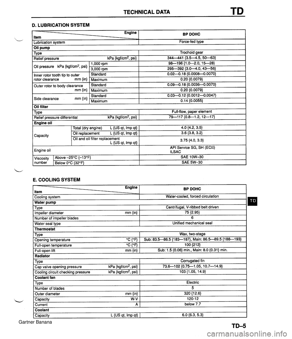
TECHNICAL DATA D. LUBRICATION SYSTEM - Engine ltem BP DOHC - -. Lubrication system Force-fed type E. COOLING SYSTEM Trochoid gear 344-41 I3.5--4.5,s-31 9&l96 {I .&2.0, 15--28) 295-392 {3.0-4.0,43-56) 0.02-0.1 8 {0.000&0.0070) 0.20 {0.0079) 0.09-0.18 (0.0036-0.0070) 0.20 {0.0079) 0.03-0.1 2 {0.0012-0.0047) 0.14 (0.0055) TY pe Relief pressure kPa {kgf/cm2, psi) Oil pressure kPa {kgf/cm2, psi) Inner rotor tooth tip to outer rotor clearance mm {in) Outer rotor to body clearance mm {in) Side clearance mm {in) Water seal type I Unified mechanical seal Thermostat 1,000 rpm 3,000 rpm Standard Maximum Standard Maximum Standard Maximum Oil filter Engine ltem - - Cooling system . . Impeller diameter mm {in) Number of impeller blades Type Relief pressure differential kPa {kgf/cm2, psi) BP DOHC Water-cooled, forced circulation - 75 i2.95) 6 Full-flow, paper element 74-1 17 {0.&1.2, 12-1 7) TY pe . ., . . . - Radiator I Water pump Wax, two-stage v. . . Full-open temperature "c {OF) Full-open lift mm {in) Engine oil TVD~ O~enina tem~erature "C con I Sub: 83.5-86.5 U83-187). Main: 86.5-89.5 (1 88-1 931 100 (21 2) Sub: 1.5 (0.06) min., Main: 8.0 (0.31) min. -. . - . . Cooling circuit checking pressure kPa {kgflcmz, psi) I 103 {I .05, 14.9) I Centrifugal, V-ribbed belt driven TY pe I Coolant fan I 4.0 (4.2, 3.5) 3.6 {3.8,3.2) 3.75 (4.0, 3.3) API Service SG, SH (ECII) ILSAC Capacity Corrugated fin viscosity Above -25°C (-1 3°F) SAE 1 OW-30 number Below 0°C {3Z°F) SAE 5W-30 Total (dry engine) L {US qt, Imp qt) Oil replacement L {US qt, Imp qt) Oil and oil filter replacement L {US qt, Imp qtl Cap valve o~enina pressure kPa {krrf/cm2, psi} 1 73.6--102 {0.75--1.05, 10.7-14.91 Capacity W-V I 120-1 2 Current A 1 below 7.7 Engine oil Type Number of blades Outer diameter mm {in) Coolant Capacity L {US qt, Imp qt) I 6.0 {6.3,5.3) Electric 5 320 (1 2.61 Gartner Banana
Page 1120 of 1708
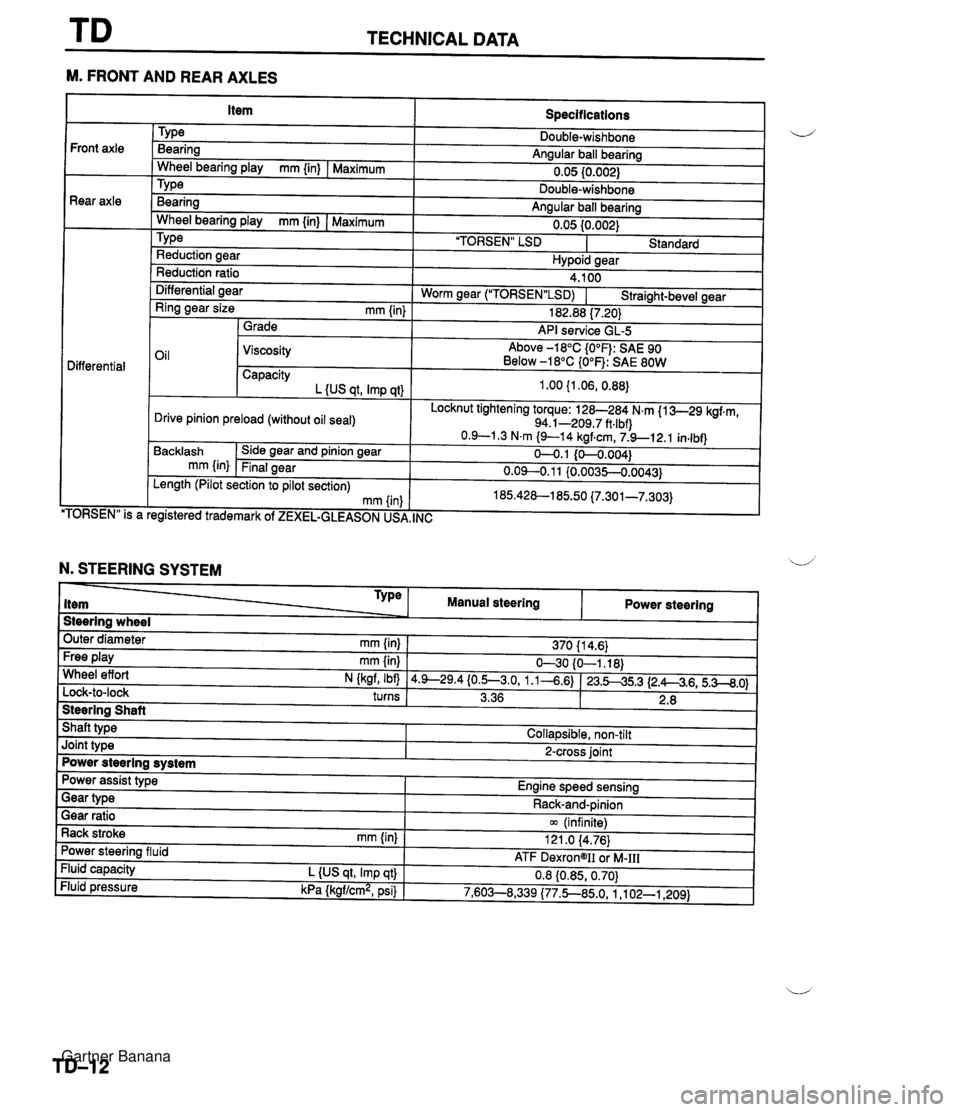
TECHNICAL DATA --- M. FRONT AND REAR AXLES Specifications TY pe Bearing Angular ball bearing 0.05 10.002) Front axle Rear axle - Wheel bearing play mm {in) I Maximum Bearina Anaular ball bearina . .. Wheel bearina plav mm {in) I Maximum " " 0.05 {0.002) 'TORSEN" LSD I Standard TY pe Reduction aear Hvpoid sear Reduction ratio Differential aear 4.100 Worm near ("1ORSEN"LSD) I Straiaht-bevel gear - - Ring gear size mm {in) 1 Grade 182.88 17.201 API service GL-5 Oil 1 Viscosity Above -18°C {O°F): SAE 90 Below -18°C {O°F): SAE 80W Differential Capacity L {US at. Imp at) Locknut tightening torque: 128-284 N.m {I 3-29 kgf.m, 94.1-209.7 ft.lbf) Drive pinion preload (without oil seal) TORSEN" is a Backlash mm {in) . , egistered trademark of ZEXEL-GLEASON US, Side gear and pinion gear Final gear , INC Length (Pilot section to pilot section) mm (in N. STEERING SYSTEM Steering wheel Outer diameter mm {in} 1 370 11 4.6) Type item Free play mm {in) I 630 {O-1.18) Wheel effort N (kaf, Ibfl 14.9--29.4{0.5--3.0, 1.1-4.6) 123.545.3 12.A4.6,5.3--8.0) turns I 3.36 1 2.8 I 1 Manual steering Steering Shaft Shaft type I Collapsible, non-tilt Power steering Joint type I 2-cross joint Power steering system Gear ratio 1 m (infinite) Rack stroke rnm {in) I 121 .O 14.76) Power assist type Engine speed sensing Power steering fluid Fluid capacity L {US qt, Imp qt} Fluid pressure kPa {kgf/cm2, psi) Gear type - - ATF DexrongII oi M-111 0.8 {0.85,0.70) 7,603--8,339 (77.5850, 1 ,I 02-1,209) Rack-and-pinion Gartner Banana
Page 1122 of 1708

TECHNICAL DATA R. SUSPENSION Front sus~ension I i/ Differential - . - ~- Coil springs MT I AT Shock absorbers "TORSEN" LSD TY ~a Cylindrical double-acting, low-pressure gas charged Standard Stabilizer Double-wishbone Torsion bar Wire diameter mm {in) Coil inner diameter mm {in} Rear suspension Tv~e I Double-wishbone TY pe Diameter mm {in) 20.0 (0.79) I Identification color 11 .O {0.43} 83.0 f3.27) . . Free length mm {in) Coil number 19.0 {0.75} . . 292.5 (1 1.52) 1 302.0 {I 1.89) 6.32 I - . I1 . ,I . , I Shock absorbers Cylindrical double-acting, low-pressure gas charged White I I Identification color I Yellow I Green I Blue Torsion bar 12.0 (0.471 1 11 .O 10.43) .a Stabilizer TYPe Diameter mm {in) Coil springs Wheel alignment I Front wheel alignment (Unladen'') I I - Caster angle*3 King pin angle I tun'aoen 'I 1 Camber angle'2 -0°43' 2 30' I I - Wire diameter mm {in) Coil inner diameter mm {in) Free length mm {in} Coil number Maximum steering angle 4O26' -c 45' 11 "20' Rear wheel alignment ,, l-l_A_-*i, *1 Fuel tank full; radiator coolant and engine oil at specified level, and spare tire, jack, and tools in designated position. *2 Difference between left and right must not exceed lo. *3 Difference between left and right must not exceed 1'30'. 10.1 (0.40) Inner Outer 10.2 I0.40) mm (in) Camber ana~e*~ J 3 + 3 10.12 r 0.12) 0°18' 2 18' -. - 3 r 3 {0.12 2 0.12) 0'24' 2 45' 37O23' 2 2" 32O32' 2 2" Total toe-in 83.0 i3.27) U' mm {in} degree 348.5 113.72) Total toe-in 356.5 {I 4.04) dearee 7.68 0'18' & 18' 7.96 Gartner Banana
Page 1124 of 1708

SPECIAL TOOLS .................... GENERAL INFORMATION ST- 2 ..................................... ENGINE ST- 3 CLUTCH AND MANUAL TRANSMISSION ...... ST- 4 ................. AUTOMATIC TRANSMISSION ST- 5 .............................. DIFFERENTIAL ST- 6 ................... FRONT AND REAR AXLES ST- 7 ......................... STEERING SYSTEM ST- 7 .......................... BRAKING SYSTEM ST- 9 ........... FRONT AND REAR SUSPENSIONS ST-1 0 CHECKERS AND OTHER EQUIPMENT ........ ST-10 4SUOTX-001 Gartner Banana
Page 1129 of 1708

ST SPECIAL TOOLS DIFFERENTIAL rooL NUMBER a DESCRIPTION PRIORITY TOOL NUMBER~ DESCRIPTION PRIORITY ILLUSTRATION 49 F027 005 Attachment @62 Hanger, differential carrier Collar Adjustment wrench, side bearing 49 8531 565 Pinion model 49 GO30 338 Attachment E 49 F027 004 Attachment @80 Gauge body, pinion height 49 BOO1 795 Installer, oil seal 49 0305 555 Sauge block 49 U027 003 Installer, oil seal nstaller, rubber wshing Holder, coupling ilange Gartner Banana
Page 1257 of 1708

GENERAL SERVICE INFORMATION L ANTI-CORROSION TREATMENT When replacing body panels, always apply body sealer, anti-rust treatment. or undercoating ac- cording to the requirements of the market. Application of surface agent and body sealer After first applying the coating of surfacing agent, apply body sealer where necessary. Note For locations where application of body sealer is difficult after installation, apply .t-before the installation. Application of rust inhibitor Undercoating Apply rust inhibitor to the back of welded areas, Use antirust treatment for underbody welding using an installation hole or a gap near that spots and wheel housings. section. Gartner Banana
Page 1258 of 1708

GENERAL SERVICE INFORMATION JACK AND SAFETY STAND POSITIONS FRONT Jack position: Center of crossmember REAR Jack position: Center of differential Safety stand positions: Side sills I Safety stand positions: Side sills VEHICLE LIFT (2-SUPPORT TYPE) POSITIONS FRONT Frame Side sills REAR Frame Side sills Gartner Banana
Page 1348 of 1708
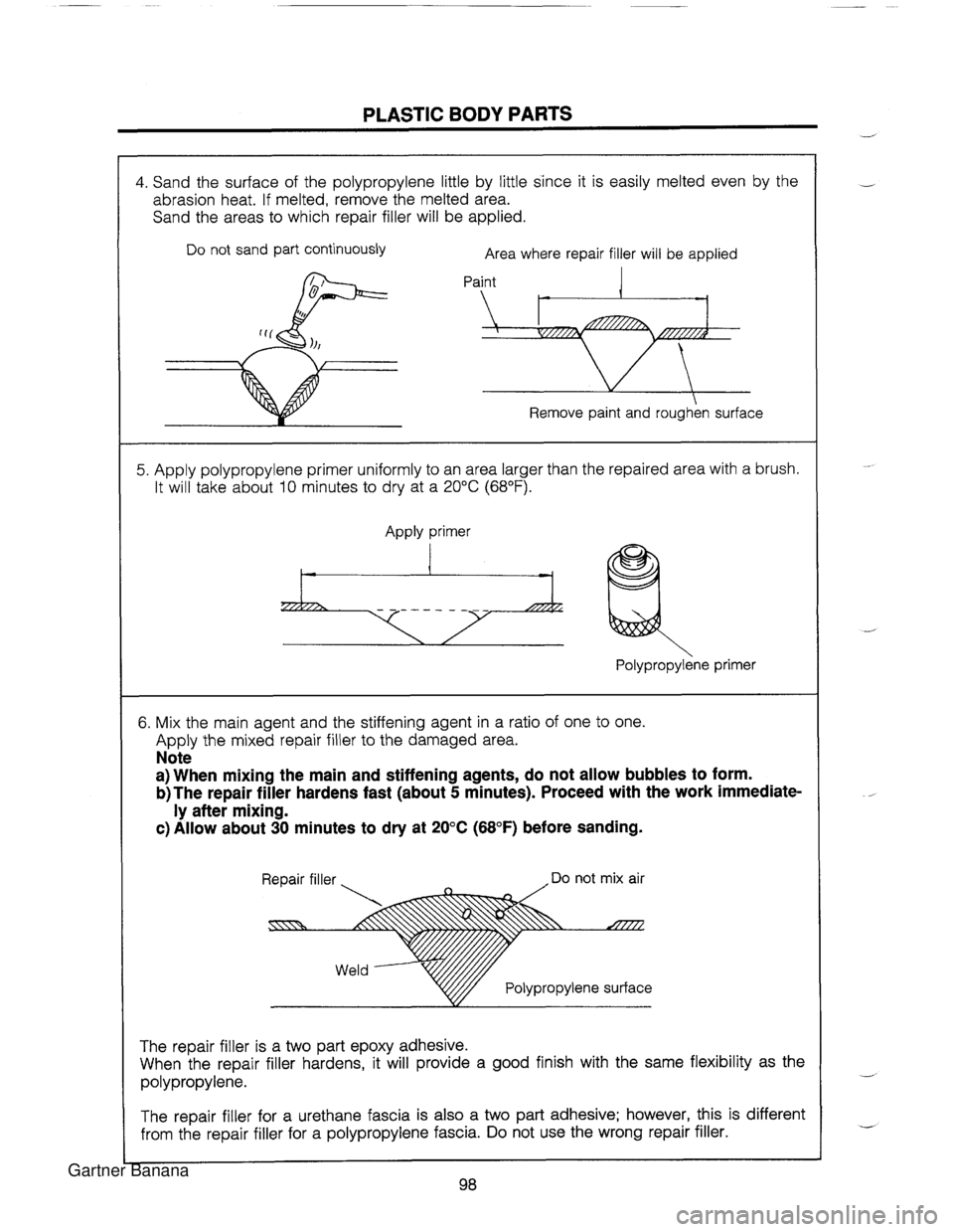
PLASTIC BODY PARTS 4. Sand the surface of the polypropylene little by little since it is easily melted even by the abrasion heat. If melted, remove the melted area. Sand the areas to which repair filler will be applied. I Do not sand part continuously Area where repair filler will be applied Paint Remove paint and roughen surface 5. Apply polypropylene primer uniformly to an area larger than the repaired area with a brush. It will take about 10 minutes to dry at a 20°C (68°F). Apply primer ~ol~~ro~~lene primer 6. Mix the main agent and the stiffening agent in a ratio of one to one. Apply the mixed repair filler to the damaged area. Note a) When mixing the main and stiffening agents, do not allow bubbles to form. b)The repair filler hardens fast (about 5 minutes). Proceed with the work immediate- ly after mixing. c) Allow about 30 minutes to dry at 20°C (68°F) before sanding. Repair filler . ,Do not mix air V@// Polypropylene surface The repair filler is a two part epoxy adhesive. When the repair filler hardens, it will provide a good finish with the same flexibility as the polypropylene. The repair filler for a urethane fascia is also a two part adhesive; however, this is different from the repair filler for a polypropylene fascia. Do not use the wrong repair filler. Gartner Banana