engine coolant MAZDA MX-5 1994 Repair Manual
[x] Cancel search | Manufacturer: MAZDA, Model Year: 1994, Model line: MX-5, Model: MAZDA MX-5 1994Pages: 1708, PDF Size: 82.34 MB
Page 287 of 1708

COOLANT FAN CONTROL COOLANT FAN CONTROL OUTLINE The PCME controls the coolant fan and the condenser fan to provide more efficient fan control. This 4 improves the performance reliability and stability during idling of an engine. The coolant fan is normal when it start to operate with the data link connector TEN terminal grounded and the accerelator pedal is depressed (Ignition switch ON). IGNITION SWITCH OFF CONDENSER FAN MOTOR PCME RELAY I& MAGNETIC CLUTCH I COOLANT FAN RELAY Q COOLANT FAN MOTOR Gartner Banana
Page 288 of 1708

COOLANT FAN CONTROL F COOLANT FAN The coolant fan rotates at a constant velocity. 'L / Operation Condition TEN TERMINAL (DATA LINK CONNECTOR) IDLE SWITCH -----' OFF EXCEPT AT STARTING 'I ENGINE COOLANT TEMPERATURE ABOVE 97C0 (206.6F0) 1 COOLANT FAN - - ENGINE COOLANT TEMPERATURE SENSOR FAILED I A/C OPERATING CONDENSER FAN The condenser fan is operated by PCME. r The condenser fan rotates at a constant velocity. Operation Condition Except during acceralation Except at starting Other than wide open throttle Air conditioner is operating The condenser fan operates when above-mentioned conditions are satisfied. Engine coolant temperature is above 108°C (226.4OFj. TEN terminal grounded and idle switch off. Gartner Banana
Page 291 of 1708

CONTROL SYSTEM STRUCTURAL VIEW i 1. Powertrain control module (engine) 6. Heated oxygen sensor Inspection . . . . . . . . . . . . . . . . . . page F-144 Inspection . . . . . . . . . . . . . . . . . . page F-156 Removal / Installation . . . . . . . . page F-143 Replacement . . . . . . . . . . . . . . . page F-156 2. Crankshaft position sensor 7. Main relay Removal . . . . . . . . . . . . . . . . . . . page F-153 Inspection . . . . . . . . . . . . . . . . . . page F-156 lnspection . . . . . . . . . . . . . . . . . . page F-153 8. Clutch switch Installation . . . . . . . . . . . . . . . . . page F-153 Inspection . . . . . . . . . . . . . . . . . . page F-157 3. Mass airflow sensor Replacement . . . . . . . . . . . . . . . page F-157 System inspection . . . . . . . . . . . page F-152 9. Neutral switch Inspection . . . . . . . . . . . . . . . . . . page F-152 Inspection . , . . . . . . . . . . . . . . . . page F-157 4. Engine coolant temperature sensor Replacement . . . . . . . . . . . . . . . page F-157 Removal . . . . . . . . . . . . . . . . . . . page F-154 10. Steering pressure sensor Inspection . . . . . . . . . . . . . . . . . . page F-154 Inspection . . . . . . . . . . . . . . . . . . page F-158 Installation . . . , . . . . . . . . . . . . . page F-154 Replacement . . . . . . . . . . . . . . . page F-158 5. Throttle position sensor -,' Inspection . . . . . . . . . . . . . . . . . . page F-155 Adjustment . . . . . . . . . . . . . . . . . page F-155 Replacement . . . . . . . . . . . . . . . page F-156 Gartner Banana
Page 294 of 1708

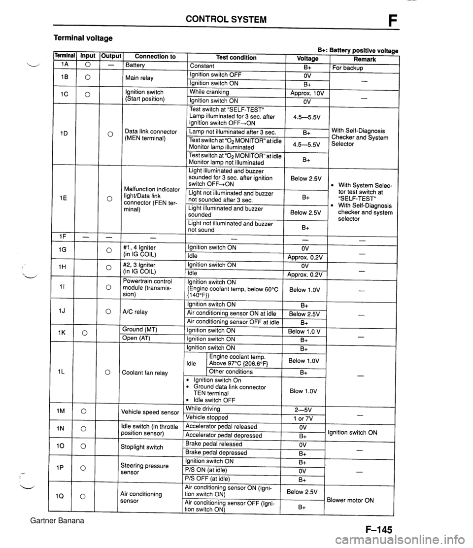
CONTROL SYSTEM F Terminal voltage B+: Battery positive voltage Test condition I Voltage I Remark - - - - - - - - - - - - - - - - - - Connection to Battery Constant Ignition switch OFF Main relay - B+ OV lgnition switch (Start position) For backup - Ignition switch ON While cranking Lamp illuminated for 3 sec. after 1 4.5-5.5V ianition switch OFF+ON 1 B+ Approx. 1 OV Ignition switch ON - - OV Data link connector (MEN terminal) Test switch at "SELF-TEST" .. Lamp not illuminated after 3 sec. Test switch at "02 MONITOR" at idle Monitor lam illuminated & 4.5-5.5v . . I Malfunction indicator IighVData link connector (FEN ter- minal) With Self-Diagnosis Checker and System Selector Test switch at "02 MONITOR" at idle Monitor lamp not illuminated Light illuminated and buzzer sounded for 3 sec. after ignition switch OFF-ON B+ tor tesiswitch at "SELF-TEST" With Self-Diagnosis checker and system selector Below 2.5V 1 Light illuminated and buzzer sounded 1 Below 2.5V I With System Selec- Light not illuminated and buzzer not sounded after 3 sec. I Light not illuminated and buzzer 1 n. 1 B+ not sound I D+ 1 - #I, 4 lgniter (in IG COIL) #2,3 Igniter (in IG COIL) Powertrain control module (transmis- sion) - Ignition switch ON Idle Ignition switch ON Idle lgnition switch ON (Engine coolant temp, below 60°C {I 40°F)) Ignition switch ON AtC relay Air conditioning sensor ON at idle Air conditioning sensor OFF at idle Ground (MT) - OV Approx. 0.2V OV Approx. 0.2V Below 1 .OV B+ Below 2.5V B+ - - - - , * Open (AT) - Ignition switch ON ( Below 1 .O V I Engine coolant temp. I Below .OV I ldle Above 97°C (206.6OF1 Ignition switch ON I I B+ Ignition switch ON Coolant fan relay B+ . - Other conditions lgnition switch On dround data link connector TEN terminal I Blow 1.0" I B+ Vehicle speed sensor ldle switch OFF While driving Vehicle sto~wed ldle switch (in throttle position sensor) 2-5V 1 or 7V . , Accelerator pedal released Accelerator ~edal de~ressed - Stoplight switch OV B+ Brake pedal released Brake ~edal deoressed lgnition switch ON Steering pressure sensor OV B+ I I - Ignition switch ON B+ - PIS ON (at idle) PIS OFF (at idle) Air conditioning sensor Air conditioning sensor ON (Igni- tion switch ON) Air conditioning sensor OFF (Igni- tion switch ON) OV B+ - Below 2.5V B+ Blower motor ON Gartner Banana
Page 295 of 1708

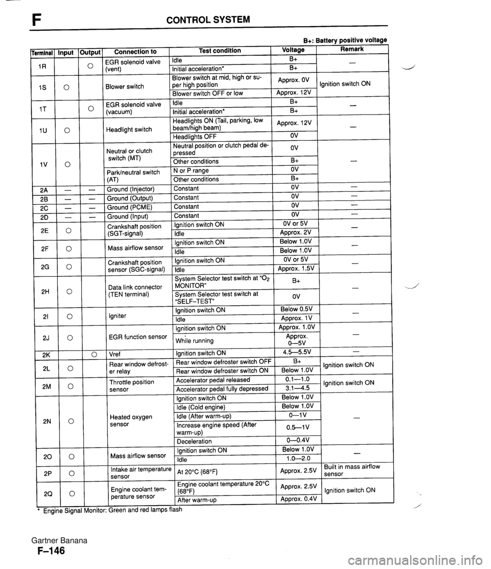
F CONTROL SYSTEM B+: Battery positive voltage Connection to 1 Test condition 1 Voltage I Remark I -- EGR solenoid valvi Idle B+ Blower switch -- EGR solenoid valve (vacuum) :vent) Initial acceleration* Blower switch at mid, high or su- per high position Blower switch OFF or low Headlight switch Neutral or clutch switch (MT) B+ Idle ParWneutral switch (AT) Ground (Injector) Ground (Output) Ground (PCME) Approx. OV - Approx. 12V B+ Headlights ON (Tail, parking, low beamfhigh beam) Headlights OFF Neutral position or clutch pedal de- pressed Other conditions Ground (Input) Crankshaft position (SGT-signal) Ignition switch ON N or fJ range Other conditions Constant Constant Constant -. Mass airflow sensor .. . . EGR function sensor I while running Approx. 0-5v Initial acceleration* Approx, 2V OV ov B+ Constant Ignition switch ON Idle Crankshaft position sensor (SGC-signal) Data link connector (TEN terminal) Igniter I I I Vre f I lanition switch ON 1 4.5-5.9.' 1 - B+ - OV B+ OV OV OV Ignition switch ON Idle - - - OV OV or 5V ADD~OX. 2V - - Ignition switch ON Idle System Selector test switch at "02 MONITOR" System Selector test switch at "SELF-TEST" Ignition switch ON Idle lanition switch ON I . . I I 1 Ignition switch ON I Below 1 .OV I I - - . . Below 1 .OV Below 1 .OV ear window defrost- er relay Throttle position sensor Heated oxygen sensor - OV or 5V Approx. 1.5V B+ ov Below 0.5V Approx. 1 V Approx. 1 .OV - - - " Rear window defroster switch OFF Rear window defroster switch ON Accelerator pedal released Accelerator ~edal fullv de~ressed Mass airflow sensor B+ Below 1 .OV 0.1-1 .o 3.14.5 Intake air temperature sensor Engine coolant tem- perature sensor lgnition switch ON lgnition switch ON Ignition switch ON Idle ireen and red lamps flash At 200C {680Fj Engine coolant temperature 20°C {680F) After warm-up Below 1 .OV 1 .O-2.0 - Approx. 2.5V Approx. 2.5V Approx. 0.4V Built in mass airflow lgnition switch ON Gartner Banana
Page 296 of 1708

CONTROL SYSTEM F Connection to I Test condition I Hot condition: Enaine coolant Input - temp. above 70°C (1 58"~) and in- PRC solenoid valve take air temp. above 50°C (122°F) for 150 sec. after enaine startina Output 0 0 0 0 0 0 0 0 0 " " Other conditions lanition switch On - Condenser fan relay Engine coolant temp. Idle above 108°C 1226°F) I I Other conditions ' I lgnition switch ON Fuel pump relay ldle I I lanition switch ON Fuel injector No.1 1,900 rpm (After warm-UD) I lgnition switch ON Fuel injector No.2 ldle Deceleration from 3,000 rprn to 1,900 rpm (After warm-up) lgnition switch ON IAC valve ldle lgnition switch ON Purge solenoid valve ldle Fuel injector No.3 lgnition switch ON ldle Deceleration from 3,000 rpm to 1,900 rpm (After warm-up) lanition switch ON Fuel injector No.4 Idle Deceleration from 3,000 rpm to 1,900 rpm (After warm-up) Below 1 .OV -1 Below 1 .OV B+ - Approx. OV Engine Signal Moni- * Engine Signal Moni- tor: Green and red Approx. 12V I lamps flash B+: Battery positive voltage Voltage I Remark * Engine Signal Moni- tor: Green and red Engine Signal Moni- Gartner Banana
Page 300 of 1708

CONTROL SYSTEM B+: Battery positive voltage Terminal Connection to Abnormal voltaae Possible cause Mass airflow sensor (Intake air temperature sensor) Refer to Code No.10 troubleshooting (Refer to page F-87) Always OV or approx. 5V Intake air temperature sensor malfunction (Refer to page F-152) Refer to Code No.09 troubleshooting (Refer to page F-87) Engine coolant temper- ature sensor Always OV or approx. 5V r Engine coolant temperature sensor malfunction (Refer to page F-154) Refer to Code No.25 Troubleshooting (Refer to page F-91) Always OV or B+ PRC solenoid valve r Open or short circuit in wiring from condenser fan relay to PCME terminal 25 PCME malfunction Open or short circuit in wiring from fuel pump relay to PCME terminal 2T Condenser fan relay Always below 2.OV Fuel pump relay Always below 1 .OV Main relay malfunction (Refer to page F-156) r Open or short circuit in wiring from fuel injector to PCME terminal 2U or 2V Always OV Fuel injector ldle air control valve Purge solenoid valve Always B+ Always OV or B+ Always OV or B+ PCME malfunction r Refer to Code No.34 troubleshooting (Refer to page F-93) ldle air control solenoid valve malfunction (Refer to page F-I 06) r Refer to Code No.26 troubleshooting (Refer to page F-91) r Purge solenoid valve malfunction (Refer to pane F-132) -- Fuel injector Always OV Main relay malfunction (Refer to page F-156) Open or short circuit in wiring from fuel injector to PCME terminal 2Y or 22 Always B+ PCME malfunction Gartner Banana
Page 303 of 1708

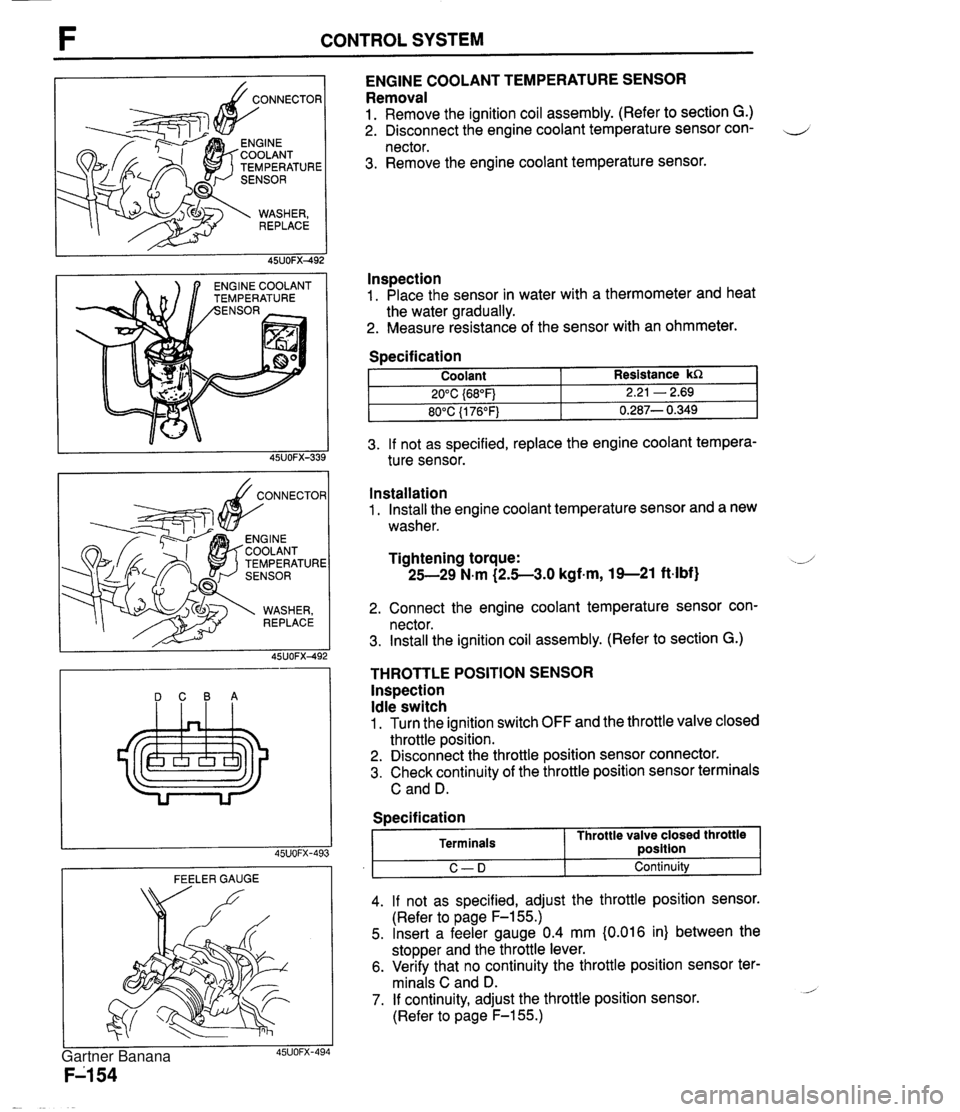
CONTROL SYSTEM TEMPERATURE NGlNE COOLANT EMPERATURE ENGINE COOLANT TEMPERATURE SENSOR Removal 1. Remove the ignition coil assembly. (Refer to section G.) 2. Disconnect the engine coolant temperature sensor con- 4 nector. 3. Remove the engine coolant temperature sensor. lnspection 1. Place the sensor in water with a thermometer and heat the water gradually. 2. Measure resistance of the sensor with an ohmmeter. 3. If not as specified, replace the engine coolant tempera- ture sensor. Specification DCBA Coolant 20°C {68"F) 80°C {I 76°F) FEELER GAUGE Resistance kR 2.21 - 2.69 0.287- 0.349 Installation 1. Install the engine coolant temperature sensor and a new washer. Tightening torque: -J 25-29 N.m (2.5-3.0 kgf-m, 19--21 ft-lbf) 2. Connect the engine coolant temperature sensor con- nector. 3. Install the ignition coil assembly. (Refer to section G.) THROTTLE POSITION SENSOR lnspection Idle switch 1. Turn the ignition switch OFF and the throttle valve closed throttle position. 2. Disconnect the throttle position sensor connector. 3. Check continuity of the throttle position sensor terminals C and D. I C-D I Continuity 4. If not as specified, adjust the throttle position sensor. (Refer to page F-155.) 5. Insert a feeler gauge 0.4 mm {0.016 in) between the stopper and the throttle lever. 6. Verify that no continuity the throttle position sensor ter- minals C and D. - 7. If continuity, adjust the throttle position sensor. (Refer to page F-155.) Specification Terminals Throttle valve closed throttle ~osition Gartner Banana
Page 423 of 1708

K MECHANICAL SYSTEM TEST MECHANICAL SYSTEM TEST PREPARATION SST STALL TEST 49 0378 400A Gauge set, oil pressure 49 801 9 901 Gauge, oil pressure For oil pressure test For oil pressure test This test is performed to determine if there is slippage of the friction elements or malfunction of the hy- draulic components. Preparation 1. Check the engine coolant, engine oil, and ATF levels before testing. 2. Warm the engine thoroughly to raise the ATF temperature to operating level (50--80°C, 122-176°F). 3. Engage the parking brake and use wheel chocks at the front and rear of the wheels. ENGAGE PARKING BRAKE WARM UP ENGINE COOLANT LEVEL ENGINE OIL LEVEL TEMPERATURE 60-70°C (1 40-1 58°F) ATF LEVEL Gartner Banana
Page 736 of 1708

OUTLINE OUTLINE SPECIFICATIONS Front Suspension - Transmission item (Stabilizer Specifications MT I AT - I Susoension tvoe I . , . , I . , Shock absorber Cylindrical double acting, low-pressure-gas charged I Double-wishbone TY pe Torsion bar Coil spring I - Diameter mm linl I 20.0 10.79) Identification mark color 19.0 (0.75) White Wire diameter mm (in) Coil inner diameter mm {in) I Blue Free length mm {in) Coil number 11 .O (0.43) 83 i3.27) 11 .O (0.43) 83 (3.27) 292.5 (1 1 32) 6.32 3 +. 3 (0.12 + 0.12) 0°18' + 18' Total toe-in I - I 35UORX-001 Rear Suspension 302.0 (1 1.89) 6.32 mm {in) degree Total toe-in (per side) 1 degree Front wheel alignment (Unladedt1) 0°09' +. 09' Caster anglee3 4"26' +. 45' Kingpin angle 11 "20' Maximum steering angle Transmission Specifications MT I AT Item Differential - Suspension type Inner Outer "TORSEN" LSD 1 Standard Double-wishbone Coil springs 370 23' a 2" 32" 32' -t 2" Camber anglee2 Torsion bar 12.0 (0.47) 1 11.0 (0.43) 1 11 .O (0.43) Cylindrical double acting, low-pressure-gas charged - Stabilizer Identification mark color Wire diameter mm {in) 0°24' + 45' Type Diameter mm {in) I Coil number I 7.68 I 7.96 I Shock absorber Yellow 10.1 {0.40} Coil inner diameter mm {in) Free length mm {in) Green 10.2 {0.40) 35UORX-002 *I Fuel tank full; radiator coolant and engine oil at specified levels; spare tire, jack, and tools in designated positions. '2 Difference between left and right must not exceed I O. '3 Difference between left and right must not exceed 1'30'. "TORSEN" is a registered trademark of ZEXEL-GLEASON USA.INC 83 I3.27) 348.5 j13.72) Rear wheel alignment (Unladed*') 83 (3.27) 356.5 (1 4.04) Total toe-in Total toe-in (per side) mm (in) degree degree 3 -c 3 (0.12 + 0.121 0°18' + 18' 0°09' + 09' Camber angle*2 -0°43' 2 30' Gartner Banana