engine MAZDA MX-5 1994 Manual PDF
[x] Cancel search | Manufacturer: MAZDA, Model Year: 1994, Model line: MX-5, Model: MAZDA MX-5 1994Pages: 1708, PDF Size: 82.34 MB
Page 141 of 1708

ENGINE COOLANT COOLANT PROTECTION SPECIFIC GRAVITY COOLANT TEMPERATURE "C (OF) 45UOEX-00 Coolant Protection Caution The engine has aluminum parts that can be dam- aged by alcohol or methanol antifreeze. Do not use alcohol or methanol in the cooling system. Use only ethylene-glycol-based coolant. Use only soft (demineralized) water in the coolant mixture. Water that contains minerals will cut down on the coolant's effectiveness. 1. Measure the coolant temperature and specific gravity with a thermometer and a hydrometer. 2. Determine the coolant protection by referring to the graph shown. If the coolant protection is not proper, add water or cool- ant. Antifreeze solution mixture percentage I Coolant protection I I Above -1 6°C (3°F) 1 65 1 35 1 1.054 1 REPLACEMENT Draining Above -26°C {-15°F) Above -40°C I-40°F} Warning Removing the radiator cap or the coolant drain plug while the engine is running, or when the en- gine and radiator are hot is dangerous. Scalding coolant and steam may shoot out and cause seri- ous injury. If may also damage the engine and cooling system. Turn off the engine and wait until it is cool. Even then, be very careful when removing the cap. Wrap a thick cloth around it and slowly turn it counterclockwise to the first stop. Step back while the pressure escapes. When you're sure all the pressure is gone, press down on the cap-still using a cloth - turn it, and remove it. 1. Remove the radiator cap and loosen the drain plug. 2. Drain the coolant into a container. 3. Flush the cooling system with water until all traces of col- or are gone, then let the system drain completely. 4. Install the drain plug. 55 45 45 55 1.066 1.078 Gartner Banana
Page 142 of 1708

E ENGINE COOLANT REFILLING Use the proper amount and mixture of ethylene-glycol based coolant. (Refer to Coolant Protection, page E-5.) 1. Slowly pour the coolant into the radiator up to the coolant filler port. Filling pace: 1.0 L (1.1 US qt, 0.9 Imp qt}/min. max 2. Fill the coolant reservoir up to the FULL level. 3. Fully install the radiator cap. 4. Start the engine and let it idle until it warms up. 5. If the temperature increases beyond normal, there is ex- cessive air in the system. Stop the engine and allow it to cool; then repeat step 1-3. 6. Run the engine at 2,200-2,800 rpm for five seconds; re- peat several times. 7. Stop the engine and allow it to cool. Warning Remove the radiator cap or the coolant filler cap while the engine is running, or when the engine and radiator are hot is dangerous. Scalding cool- ant and steam may shoot out and cause serious injury. It may also damage the engine and cooling system. Turn off the engine and wait until it is cool. Even then, be very careful when removing the cap. Wrap a thick cloth around it and slowly turn it counterclockwise to the first stop. Step back while the pressure escapes. When you're sure all the pressure is gone, press ii down on the cap -still using a cloth - turn it, and remove it. 8. Remove the radiator cap and check the coolant level. If the coolant level has dropped, repeat the procedure from step 1. Gartner Banana
Page 143 of 1708

RADIATOR CAP RADIATOR CAP INSPECTION Radiator Cap Valve 1. Remove foreign material (such as water residue) from between the radiator cap valve and the valve seat. 2. Attach the radiator cap to a radiator cap tester (commer- cially available) with the SST. Apply pressure gradually to 73.6-1 02 kPa (0.75-1 .O5 kgf/cm2, 10.7-1 4.9 psi). 3. Wait about 10 seconds. Verify that the pressure has not decreased. PREPARATION L SST Negative Pressure Valve 1. Pull the negative pressure valve to open it. Verify that it closes completely when released. 2. Check for damage on the contact surfaces and for cracked or deformed seal packing. 3. Replace the radiator cap if necessary. 49 9200 145 Adapter set, radiator cap tester Warning Remove the radiator cap or the coolant drain plug while the engine is running, or when the engine and radiator are hot is dangerous. Scalding cool- ant and steam may shoot out and cause serious injury. It may also damage the engine and cooling system. Turn off the engine and wait until it is cool. Even then, be very careful when removing the cap. Wrap a thick cloth around it and slowly turn it counterclockwise to the first stop. Step back while the pressure escapes. When you're sure all the pressure is gone, press down on the cap - still using a cloth - turn it, and remove it. 05UOEX-014 For inspection of radiator cap valve For inspection of radiator cap valve 49 9200 147 Adapter B (Part of 49 9200 145) Gartner Banana
Page 144 of 1708

RADIATOR RADIATOR REMOVAL I INSTALLATION 1. Disconnect the negative battery cable. 2. Drain the engine coolant. (Refer to page E-5 for WARNING and procedure.) 3. Remove the undercover. 4. Remove in the order shown in the figure. 5. Install in the reverse order of removal. 1. Air intake pipe 5. Coolant fan, condenser fan 2. Radiator hose 6. Radiator 3. Coolant reservoir hose Inspection . . . . . . . . . . . . . . . . . . . . . . below 4. Coolant fan motor connector, condenser fan motor connector INSPECTION Check for the following and repair or replace as necessary. 1. Cracks, damage, and water leakage. 2. Bent fins (repair with a screwdriver). 3. Distorted or bent radiator inlet. Steps After Installation 1. Install the undercover. _i 2. Connect the negative battery cable. 3. Fill the radiator with coolant. (Refer to page E-6 for WARNING and procedure.) Gartner Banana
Page 145 of 1708
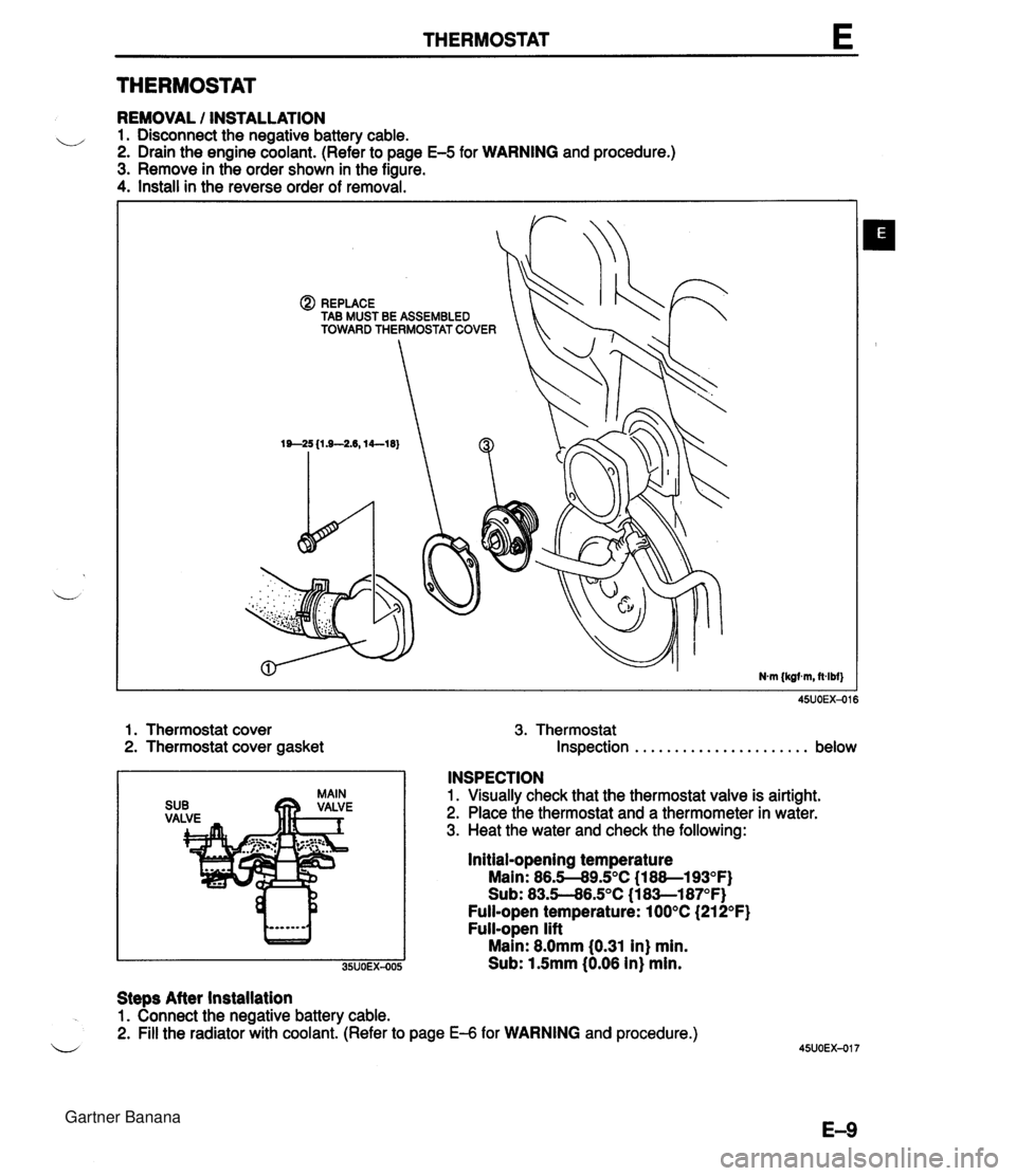
THERMOSTAT E THERMOSTAT REMOVAL / INSTALLATION u 1. Disconnect the negative battery cable. 2. Drain the engine coolant. (Refer to page E-5 for WARNING and procedure.) 3. Remove in the order shown in the figure. 4. Install in the reverse order of removal. @) REPLACE TAB MUST BE ASSEMBLED TOWARD THERMOSTAT COVER 1. Thermostat cover 3. Thermostat 2. Thermostat cover gasket Inspection . . . . . . . . . . . . . . . . . . . . . . below INSPECTION 1. Visually check that the thermostat valve is airtight. 2. Place the thermostat and a thermometer in water. 3. Heat the water and check the following: Initial-opening temperature Main: 86.5-89.S°C (1 88--193OF) Sub: 83.5--86.S°C (1 8Sl87OF) Full-open temperature: 100°C (21 2°F) Full-open lift Main: 8.0mm 10.31 in) min. Sub: 1.5mm (0.06 in) min. Steps After installation 1. Connect the negative battery cable. 2. Fill the radiator with coolant. (Refer to page €4 for WARNING and procedure.) u Gartner Banana
Page 146 of 1708

WATER PUMP WATER PUMP REMOVAL I INSTALLATION 1. Disconnect the negative battery cable. 2. Drain the engine coolant. (Refer to page E-5 for WARNING and procedure) 3. Remove in the order shown in the figure, referring to Removal Note. 4. Install in the reverse order of removal. 1. Timing belt 4. Water pump Service . . . . . . . . . . . . . . . . . . . . . Section B Inspect for cracks, damaged mounting sur- 2. PIS oil pump face, bearing condition, and leakage. Removal Note . . . . . . . . . . . . . . page E-1 1 If the water pump is damage, replace it. 3. Water hose Do not repair it. 5. Water inlet pipe Gartner Banana
Page 150 of 1708
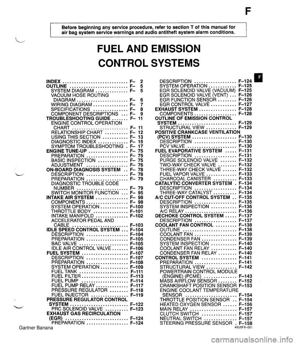
Before beginning any service procedure. refer to section T of this manual for air bag system service warnings and audio antitheft system alarm conditions . FUEL AND EMISSION CONTROL SYSTEMS INDEX ............................ F- 2 ......................... OUTLINE F- 5 .............. SYSTEM DIAGRAM F- 5 VACUUM HOSE ROUTING DIAGRAM ...................... F- 6 WIRING DIAGRAM ............... F- 7 SPECIFICATIONS ............... F- 8 COMPONENT DESCRIPTIONS ... F- 9 ....... TROUBLESHOOTING GUIDE F- 11 ENGINE CONTROL OPERATION CHART ........................ F- 11 RELATIONSHIP CHART .......... F- 12 USING THIS SECTION ........... F- 13 DIAGNOSTIC INDEX ............. F- 15 SYMPTOM TROUBLESHOOTING . F- 17 PREPARATION ................... F- 75 ............. BASIC INSPECTION F- 75 .................. ADJUSTMENT F- 76 ON-BOARD DIAGNOSIS SYSTEM . . F- 78 DESCRIPTION .................. F- 78 PREPARATION .................. F- 79 DIAGNOSTIC TROUBLE CODE NUMBER ...................... F- 79 ... SWITCH MONITOR FUNCTION F- 95 INTAKE AIR SYSTEM .............. F- 98 COMPONENTS .................. F- 98 SYSTEM OPERATION ............ F-100 THROTTLE BODY ............... F-101 INTAKE MANIFOLD .............. F-102 ACCELERATOR PEDAL AND CABLE ........................ F-103 IDLE SPEED CONTROL SYSTEM ... F-104 DESCRI PTlON .................. F-104 PREPARATION .................. F-105 BAC VALVE ..................... F-105 IDLE AIR CONTROL VALVE ....... F-106 FUEL SYSTEM .................... F-107 DESCRIPTION .................. F-107 PREPARATION .................. F-108 SYSTEM OPERATION ............ F-109 FUEL TANK ..................... F-111 FUEL FILTER .................... F-113 FUEL PUMP .................... F-114 FUEL PUMP RELAY .............. F-117 PRESSURE REGULATOR ........ F-118 FUEL INJECTOR ................ F-119 PRESSURE REGULATOR CONTROL SYSTEM ......................... F-122 PRC SOLENOID VALVE .......... F-123 EXHAUST GAS RECIRCULATION (EGR) ........................... F-124 PREPARATION .................. F-124 .................. DESCRIPTION F-124 SYSTEM OPERATION F-125 ............ EGR SOLENOID VALVE (VACUUM) F-125 EGR SOLENOID VALVE (VENT) ... F-126 ......... EGR FUNCTION SENSOR F-126 ........... EGR CONTROL VALVE F-127 ................ EXHAUST SYSTEM F-128 .................. COMPONENTS F-128 OUTLINE OF EMISSION CONTROL ......................... SYSTEM F-129 ............. STRUCTURAL VIEW F-129 POSITIVE CRANKCASE VENTILATION ................... (PCV) SYSTEM F-130 ' DESCRIPTION .................. F-I ..................... PCV VALVE F-1 ..... FUEL EVAPORATIVE SYSTEM F- .................. DESCRIPTION F- ....... PURGE SOLENOID VALVE F- ........ TWO-WAY CHECK VALVE F- ...... THREE-WAY CHECK VALVE F- ............. FUEL VAPOR VALVE F- .......... CHARCOAL CANISTER F- CATALYTIC CONVERTER SYSTEM . F- .................. DESCRIPTION F- .......... THREE-WAY CATALYST F- AIC CUT-OFF CONTROL SYSTEM . . F- .................. DESCRIPTION F- ........... SYSTEM INSPECTION F- ...................... A/c RELAY F-1 36 ..... DECHOKE CONTROL SYSTEM F-137 .................. DESCRIPTION F-137 ......... COOLANT FAN CONTROL F-138 ....................... OUTLINE F-138 .................. COOLANT FAN F-139 ............... CONDENSER FAN F-139 ........... SYSTEM INSPECTION F-140 ........... COOLANT FAN RELAY F-140 ........ CONDENSER FAN RELAY F-140 ............... CONTROL SYSTEM F-141 .................. PREPARATION F-141 ............. STRUCTURAL VIEW F-142 POWERTRAIN CONTROL MODULE .............. (ENGINE) (PCME) F-143 ........ MASS AIRFLOW SENSOR F-152 CRANKSHAFT POSITION SENSOR F-153 ENGINE COOLANT TEMPERATURE ...................... SENSOR F-154 THROTTLE POSITION SENSOR . . F-154 HEATED OXYGEN SENSOR ...... F-156 MAIN RELAY .................... F-157 ............... CLUTCH SWITCH F-157 NEUTRAL SWITCH .............. F-157 STEERING PRESSURE SENSOR . F-158 45UOFX-001 Gartner Banana
Page 152 of 1708
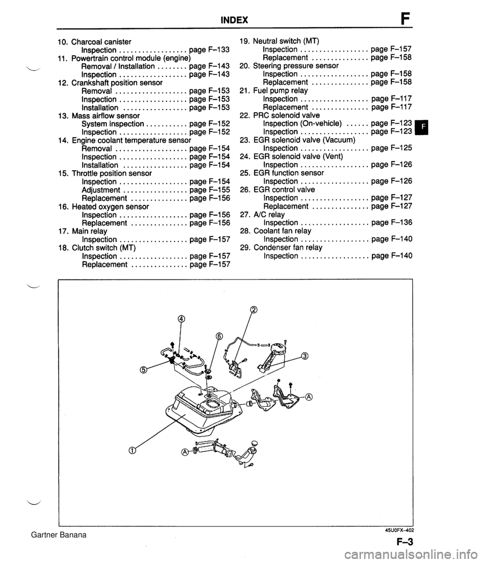
INDEX 10. Charcoal canister lnspection . . . . . . . . . . . . . . . . . . page F-133 11. Powertrain control module (engine) Removal / Installation . . . . . . . . page F-143 lnspection . . . . . . . . . . . . . . . . . . page F-143 12. Crankshaft position sensor Removal . . . . . . . . . . . . . . . . . . . page F-153 lnspection . . . . . . . . . . . . . . . . . . page F-153 lnstallation . . . . . . . . . . . . . . . . . page F-153 13. Mass airflow sensor System inspection . . . . . . . . . . . page F-152 lnspection . . . . . . . . . . . . . . . . . . page F-152 14. Engine coolant temperature sensor Removal . . . . . . . . . . . . . . . . . . . page F-154 lnspection . . . . . . . . . . . . . . . . . . page F-154 Installation . . . . . . . . . . . . . . . . . page F-154 15. Throttle position sensor lnspection . . . . . . . . . . . . . . . . . . page F-154 Adjustment . . . . . . . . . . . . . . . . . page F-155 Replacement . . . . . . . . . . . . . . . page F-156 16. Heated oxygen sensor lnspection . . . . . . . . . . . . . . . . . . page F-156 Replacement . . . . . . . . . . . . . . . page F-156 17. Main relay lnspection . . . . . . . . . . . . . . . . . . page F-157 18. Clutch switch (MT) lnspection . . . . . . . . . . . . . . . . . . page F-157 Replacement . . . . . . . . . . . . . . . page F-157 19. Neutral switch (MT) lnspection . . . . . . . . . . . . . . . . . . page F-157 Replacement . . . . . . . . . . . . . . . page F-158 20. Steering pressure sensor lnspection . . . . . . . . . . . . . . . . . . page F-158 Replacement . . . . . . . . . . . . . . . page F-158 21. Fuel pump relay lnspection . . . . . . . . . . . . . . . . . . page F-117 Replacement . . . . . . . . . . . . . . . page F-117 22. PRC solenoid valve lnspection (On-vehicle) . . . . . . page F-123 lnspection . . . . . . . . . . . . . . . . . . page F-123 23. EGR solenoid valve (Vacuum) lnspection . . . . . . . . . . . . . . . . . . page F-125 24. EGR solenoid valve (Vent) lnspection . . . . . . . . . . . . . . . . . . page F-126 25. EGR function sensor lnspection . . . . . . . . . . . . . . . . . . page F-126 26. EGR control valve lnspection . . . . . . . . . . . . . . . . . . page F-127 Replacement . . . . . . . . . . . . . . . page F-127 27. NC relay lnspection . . . . . . . . . . . . . . . . . . page F-136 28. Coolant fan relay lnspection . . . . . . . . . . . . . . . . . . page F-140 29. Condenser fan relay lnspection . . . . . . . . . . . . . . . . . . page F-140 Gartner Banana
Page 154 of 1708
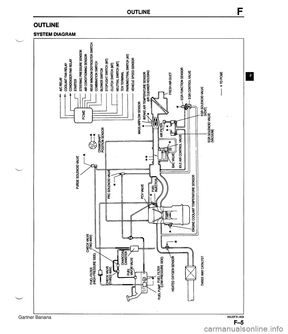
PURGE SOLENOID VALVE 7* AlC RELAY COOLANT FAN RELAY CONDENSER FAN RELAY STARTER STEERING PRESSURE SENSOR AIR CONDITIONING SENSOR ... CHECK VALVE FUEL-FILTER (HIGH-PRESSURE SIDE) / CRANKSHAFT POSITION SENSOR HEATED OXYGEN SENSOR ltT=I THREE-WAY CATALYST - REAR WINDOW DEFROSTER SWITCH COMBINATION SrmCH BLOWER SWlTCH STOPLIGHT SWITCH (MT) CLUTCH SWITCH (MT) - NEUTRALSWrrCH (MT) TEN TERMINAL PARWEUTRAL SWITCH (AT) VEHICLE SPEED SENSOR ENGINE COOLAMTEMPERATURE SENSOR EGR SOLENOID VALVE WEM) EGR SOLENOID VALVE (VACUUM) - w TO PCME Gartner Banana
Page 157 of 1708
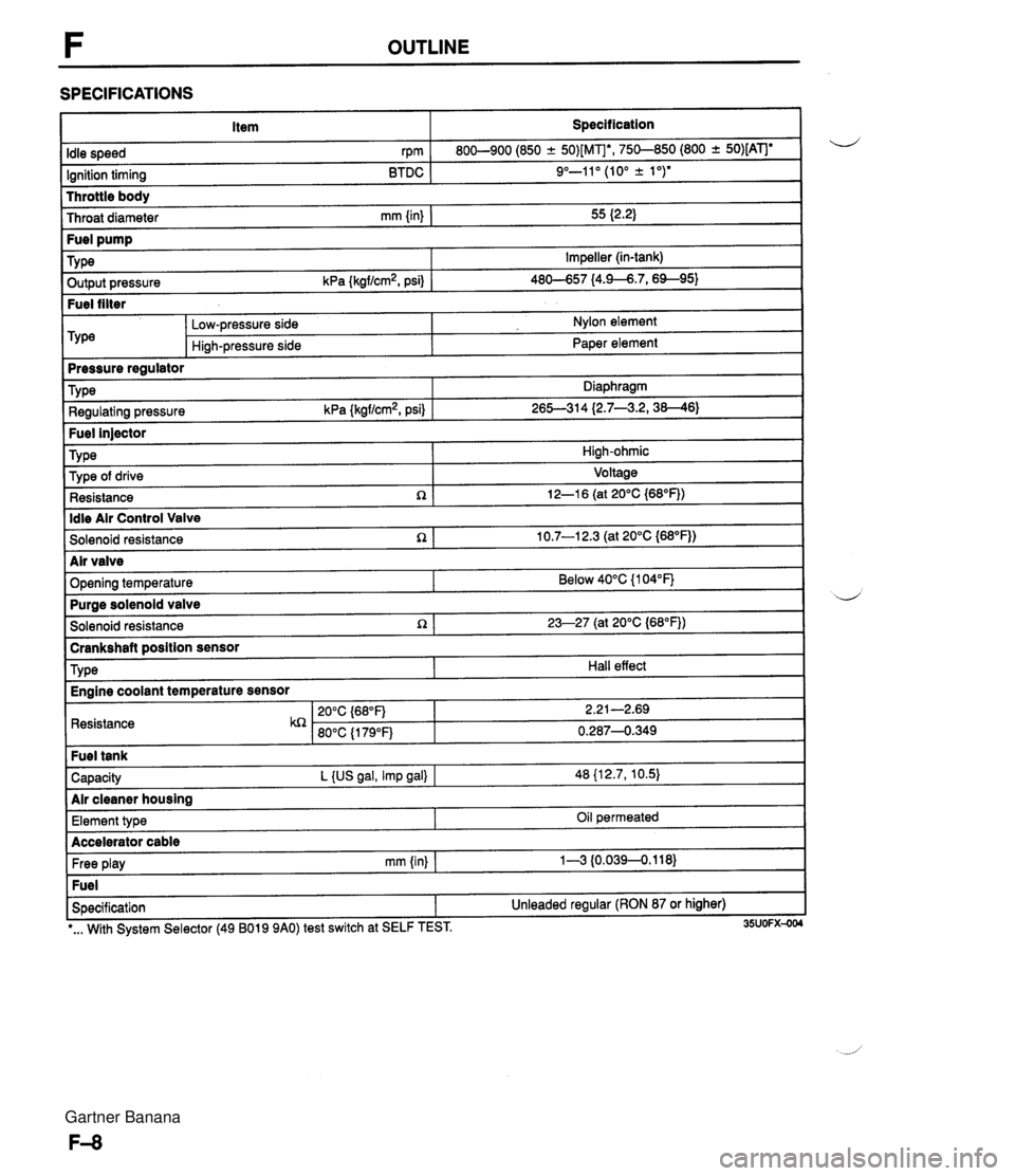
F OUTLINE SPECIFICATIONS Item Specification I Throttle body Throat diameter mm {in) I 55 I2.2) Idle speed rpm Ignition timing BTDC 800-900 (850 -+ 50)[MIb, 750-850 (800 + 50)[ATJe 9"-11" (10" k 1 ")* ~ut~~~ressure kPa {kgf/cm2, psi) 1 46-57 14.9--6.7,6%95) Fuel filter Fuel pump TY pe -- m&e regulator Impeller (in-tank) Low-pressure side Hi~h-pressure side Nylon element Paper element Fuel injector TY pe I High-ohmic Type Regulating pressure kPa {kgf/cm2, psi) Diaphragm 26S314 (2.7--3.2,38--46) ldle Air Control Valve Solenoid resistance n 1 10.7-1 2.3 (at 20°C {M°F)) Type of drive Resistance R Voltage 12-1 6 (at 20°C {68"F)) I Solenoid resistance 1 23-27 (at 20°C (68"FJ) I -- brankshaft position sensor d Air valve Opening temperature I Resistance Below 40°C {I 04°F) TY pe Capacity L {US gal, Imp gal) I 48 {12.7, 10.5) Air cleaner housing Purae solenoid valve Hall effect Engine coolant temperature sensor Free play mm (in) I 1-3 {0.0394.118) Fuel Specification 1 Unleaded regular (RON 87 or higher) Element type I I -. I *... With System Selector (49 B019 9AO) test switch at SELF TEST. 35UOFX-004 Oil permeated Accelerator cable Gartner Banana