drain bolt MAZDA MX-5 1994 Workshop Manual
[x] Cancel search | Manufacturer: MAZDA, Model Year: 1994, Model line: MX-5, Model: MAZDA MX-5 1994Pages: 1708, PDF Size: 82.34 MB
Page 49 of 1708

B ON-VEHICLE MAINTENANCE TIMING BELT Removal / lnstallation 1. Disconnect the negative battery cable. 2. Drain the engine coolant. 3. Remove the under cover. 4. Remove in the order shown in the figure, referring to Removal Note. 5. Install in the reverse order of removal, referring to lnstallation Note. (80-110 kgfmn, 7.9-10.7 Nm 13-17 Nm (125-175 kgfcm, 109-151 In4bf) Nm (kgfm, ft4bf) 45UOBX425 1. Air intake pipe 12. Spark plug 2. Upper radiator hose Removal / Installation ......... section G 3. Water hoses (Connected to thermostat 13. PCV valve housing) 14. Cylinder head cover 4. PIS andlor A/C drive belt 15. Upper timing belt cover Removal 1 Installation ....... page B- 6 16. Middle timing belt cover 5. Alternator drive belt 17. Lower timing belt cover Removal / Installation ....... page 5 6 18. Timing belt 6. Water pump pulley Removal Note ............. page B-13 7. Plate Installation Note ........... page B-14 8. Crankshaft pulley Inspection ................. page 8-58 9. Pulley lock bolt 19. Tensioner, tensioner spring Removal Note ............. page B-13 Installation Note ........... page B-14 /' Installation Note ........... page 51 5 Inspection ................. page 558 10. Pulley boss 20. Idler 11. Ignition coil and high-tension lead Inspection ................. page 8-58 Gartner Banana
Page 123 of 1708

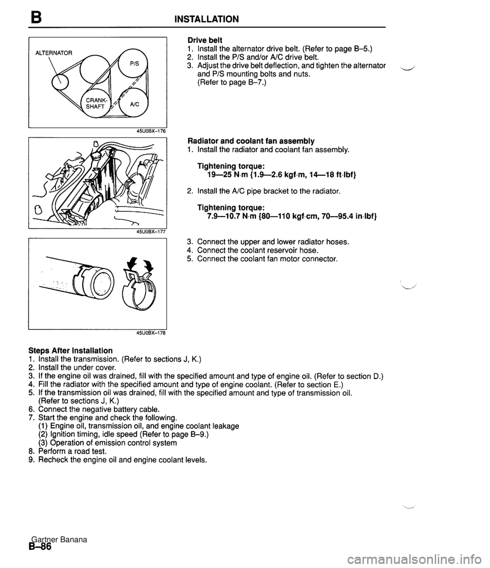
B INSTALLATION ALTERNATOR Drive belt 1. lnstall the alternator drive belt. (Refer to page B-5.) 2. lnstall the PIS and/or AIC drive belt. 3. Adjust the drive belt deflection, and tighten the alternator - and PIS mounting bolts and nuts. (Refer to page 8-7.) Radiator and coolant fan assembly 1. lnstall the radiator and coolant fan assembly. Tightening torque: 19-25 N.m (1.9-2.6 kgf.m, 14--18 ft4bf) 2. lnstall the AIC pipe bracket to the radiator Tightening torque: 7.9-10.7 N.m (80-110 kgf.cm, 70-95.4 in4bf) 3. Connect the upper and lower radiator hoses. 4. Connect the coolant reservoir hose. 5. Connect the coolant fan motor connector. Steps After Installation 1. lhstall the transmission. (Refer to sections J, K.) 2. lnstall the under cover. 3. If the engine oil was drained, fill with the specified amount and type of engine oil. (Refer to section D.) 4. Fill the radiator with the specified amount and type of engine coolant. (Refer to section E.) 5. If the transmission oil was drained, fill with the specified amount and type of transmission oil. (Refer to sections J, K.) 6. Connect the negative battery cable. 7. Start the engine and check the following. (1) Engine oil, transmission oil, and engine coolant leakage (2) Ignition timing, idle speed (Refer to page 59.) (3) Operation of emission control system 8. Perform a road test. 9. Recheck the engine oil and engine coolant levels. Gartner Banana
Page 131 of 1708

D OIL PAN OIL PAN REMOVAL / INSTALLATION 1. Disconnect the negative battery cable. 2. Drain the engine oil. (Refer to page D-5.) 3. Remove the undercover. 4. Remove in the order shown in the figure, referring to Removal Note. 5. Install in the reverse order of removal, referring to Installation Note. 94--117 (9.5-11.9,69-86) 57-78 (5.8--8.0,42-57) 69-83 {7.0-8.5,51-61) GASKET, REPLAC 7.9--10.7 Nm {60-110 kgfan, 70-95 O-RING, REPLACE 'If 64-49 (6.!%9.1,4&65) 7.9-10.7 N.m (80-110 kgf.crn, 70-95 indbf] 1. Dipstick and pipe 5. Oil pan ............. 2. Intermediate shaft Removal Note page D- 9 ........... .......... Removal / lnstllation section N Installation Note page D-10 3. Engine mount nut 6. Oil strainer 7. Oil baffle ,' ............. Removal Note page D- 9 ............. 4. Crossmember installation bolt and nut Removal Note page D- 9 ............. ........... Removal Note page D- 9 Installation Note page D- 9 Gartner Banana
Page 438 of 1708

AUTOMATIC TRANSMISSION FLUID (ATF) K REPLACEMENT 1. On level ground, jack up the vehicle and support it evenly on safety stands. Warning When the transmission and the ATF are hot, they can cause burns to the skin. Allow the transmis- sion and the ATF to cool before doing this proce- dure. 2. Loosen the oil pan installation bolts, and drain the ATF into a container. 3. Remove the oil pan and gasket. 4. Clean the oil pan and the magnet. 5. Install the oil pan along with a new gasket. Tightening torque: 5.9-7.8 N-m (60-80 kgfecm, 53-69 in-lbf) 6. Add approximately 4.0 L (4.2 US qt, 3.5 Imp qt} ATF, and check the ATF level. (Refer to page K-35.) Specified ATF: DexronmII or M-I11 Gartner Banana
Page 529 of 1708

K TRANSMISSION On-vehicle Removal 1. Disconnect the negative battery cable. 2. On level ground, jack up the vehicle and support it evenly on safety stands. w 3. Remove the exhaust pipe. (Refer to page K-45.) Warning When the transmission and the ATF are hot, they can cause burns to the skin. Allow the transmis- sion and the ATF to cool before doing this proce- dure. 4. Loosen the oil pan installation bolts, and drain the ATF into a container. 5. Disconnect the vacuum hose. 6. Remove the vacuum diaphragm, O-rings, and vacuum diaphragm rod. 7. Remove the oil pan, and the gasket. 8. Disconnect the solenoid valve connector. 9. Remove the harness from the bracket. 10. Remove the control valve body assembly. Gartner Banana
Page 531 of 1708

K TRANSMISSION VACUUM DIAPHRAGM Preparation SST Note Excessive shift shock and improper shifting often indicate a vacuum diaphragm malfunction. 49 GO32 355 Adjustment gauge Warning When the transmission and the ATF are hot, they can cause burns to the skin. Allow the trans- mission and the ATF to cool before doing this procedure. For adjustment of vacuum diaphragm rod On-vehicle Removal 1. On level ground, jack up the vehicle and support it evenly on safety stands. 2. Remove the exhaust pipe. (Refer to page K-45.) 3. Loosen the oil pan mounting bolts, and drain approx. 1.0 L (1.1 US qt, 0.9 Imp qt) of ATF. L' 4. Disconnect the vacuum hose. 5. Remove the vacuum diaphragm, O-rings, and vacuum diaphragm rod. Inspection 1. Check that the vacuum diaphragm rod moves when vac- uum is applied to the vacuum diaphragm. 2. If not correct, replace the vacuum diaphragm. Gartner Banana
Page 610 of 1708

DIFFERENTIAL M DIFFERENTIAL OIL Inspection 1. Remove the filler plug. 2. Verify that the oil is at the bottom of the filler plug hole. If it is low, add the specified oil. 3. Install the filler plug. Tightening torque: 39-54 N.m (4.0-5.5 kgf.m, 29-40 ft4bf) Replacement 1. Remove the filler and drain plugs. 2. Drain the differential oil into a suitable container. 3. Wipe the plugs clean. 4. Install the drain plug and a new washer. Tightening torque: 39-54 N.m (4.0-5.5 kgf-m, 29-40 ft4bf) 5. Add the specified oil from the filler plug until the level reaches the bottom of the plug hole. Specified oil TY pe Above -18°C (0°F): API GL-5, SAE 90 Below -18°C (0°F): API GL-5, SAE 80 Capacity: 1 .OO L {I .06 US qt, 0.88 Imp qt) 6. lnstall the filler plug. Tightening torque: 39-54 N.m (4.0-5.5 kgf.m, 29--40 ft.lbf) OIL SEAL (OUTPUT SHAFT) Replacement 1. On level ground, Jack up the vehicle and support it on safety stands. 2. Drain the differential gear oil. 3. Mark the drive shaft and output shaft flanges for proper reassembly. 4. Remove the upper arm installation bolt and nut. Gartner Banana
Page 1107 of 1708

AIR CONDITIONER u O-RING (2) Tighten the discharge valve body installation through bolts. Tightening torque: 10.8 N-m (110 kgf-cm, 95.5 in-lbf) (3) Tighten the discharge valve body installation bolts. Tightening torque: 10.8 N-m (110 kgf-cm, 95.5 in-lbf) 1 3. Pour compressor oil (ND-OILS) Pour compressor oil into the A/C compressor. Compressor oil amount: Same amount as drained, plus 20 ml(20 cc, 0.6 fl or) 14. Installation of service valve (1) Apply the compressor oil to the new O-rings. (2) Install the service valves to the compressor and tight- en the installation bolts. Tightening torque: 12.3 N-m (125 kgf-cm, 109 in-lbf) Gartner Banana
Page 1698 of 1708

ALPHABETICAL INDEX *%* ENGLISH *** CASE,T/MISSlON------------ CASE'A' , LLOWER UNIT- ----- CASE'A',COOLING UNIT----- CASE'A1 ,HEATER UNIT------ CASEIB' ,BLOWER UNLT------ CASE'B' ,COOLING UNIT----- CASE'B9,HEATER UNIT------ CASE'OUT',ASHTRAY-------- CASING,DIFFERENTIAL------ CASING,HYDRAULIC UNIT---- CASING,STOPPER----------- CATALYST ,THREE WAY------- CEILING,TOP-----.--------- CHANNEL( L) DIVISION-DOOR- CHANNEL(R)lDIVISION-DOOR- CHECKER,DOOR------------- CLAMP---------.-..--------- CLAMP,BATTERY------------ CLAMP,HOSE--------------- 1-L11 DRUM,CLUTCH-------------- 1-N8 DRUM,CONNECTING---------- 1 -H9 DRUM,DIRECT------------.- 1-F9 DRUMIREAR CLUTCH------ -- 1-C9 DUCT(L)---------------..-- 2-DB DUCT(L1 ,SIDE DEMI .-- .---- DUCT(R)----..------------- 2-C8 2-DB DUCT(R1,SIDE DEMT,------- DUCT,AIR- ---- ------------ 2-C8 DUCT,CENTER-------------- 2-Cll 2-C8 DUCTIFRESII AIR----------- 1-14 CLIP,WEATHLRSTRIP-OUTER-- 2-El1 CLIPtA',SPEEDOMETER CABLL 2-F7 CLIPIA',WEATHERSTRIP-OUT- 2-El1 CLIPIB',WIRE-BONNET------ 2-E5 CLGTH,REPAIR-TOP-------..- 2-Dli CLAMt3,HOSE-A 1 .P. /A. CLNR CLAMP,WATER HOSE--------- ELEMENTIAIR CLEANER------ 1-J4 EMBLEM,CAP-WIiE€I.--------- 1-Ll;? END,CONTROL LEVtR-------- 1 -K6 ENDlS/ROD<1ST82ND)------- 1-J6 ENl)rS/ROD(3RDB4TH;------- 1-J6 ENG:SHIFf ROD(O/TOI'&REV.) 1-K6 ENGINE,PARTIAL----------- ENGINE,SHORT------------.- 1-D3 ESCUTCHEON--------------- 1-D3 EVAPORATOR--------------- 2-ti9 2-Mll EYE BOLT K?T,31. GEAR---- 1-M12 2-116 2-L12 2-N5 COVER,5OIE-CC1----------- 2-Ki COVER,HOLE-ANTENNA------- 2-El4 COVER,HOLE-LIFT GATE----- 2-Dl0 COVER,INNER HANDLE----.--- 2-M9 COVER,INTERIOR MIRRORm--- 2-F16 COVER,JOINT-LOWER-------- 1-112 COVER,JOINT-UPPER-------- 1-112 COVER,LEVER-OPENER------- 2-L7 COVER,MAIN FUSE BLOCK---- 2- I1 4 COVER,OIL PUMP----------- COVER,REAR--------------- 1-N4 1-J3 1-K12 COVEK,RE&R-ALTERNATOR---- 1-C7 CQVER,RELAy------------..- 2-H1! COVER,ROD---------------- 1-1.6 COVER,SELECT LEVER------- 1-616 COVERISERVICE HOLE------- Z-F5 COVER,SERVO-------------- COVER,SIDE--------------- 1-N7 2-K7 COVERISPARE TIRE--------- 2-Cl6 COVER,l'HERHO------------- 1-D5 CQVER,THERMOSTAT--------- 1-D5 COVER,TIMING EELT-C. ----- 1-13 GASKET------------------- 1-C5 1-C15 1 -F3 1-H7 1-J14 1-L4 1 - L 14 1-N7 2- ~4 GASKET 8 SEAL KIT-------- 1-M9 GASKET KIT,COMPRESSOR---- 2-K11 GASKET SET ,CYL HEAD----- i -D3 GASKET SETIENGINE-------- 1-DY GASKET(C1 ,TIMING BELTCL) - 1-13 GASKEl'(INN),TIHIHG BELTCL 1-13 BASKET(L)---------------- GASKET,CAP--------------- 1-13 1-114 GASKETICONPRESSOR-------- 2-K11 GASKET,CONVERTER--------- !-Dl4 G0.SKET ,COVER PLATE------- 1-K6 GASKET,CYl.INDER WEAD----- 1-F3 GASKET,DRAIN PLUG-------- 1-li14 GASKETIDRUM SUPPORT- ----- 1 - D8 CASKET.E.G.R. VALVE------ 1-L4 CORD NO.1,HI.TENSION----- 1 -M6 CORD NO.2.HI.TENSION----- 1 -M6 CORD NO.~;HI.TENSION----- 1 -M6 CORD NU.4,HI.TENSION----- 1 -M6 CORD SET,HI.TENSION------ 1 -M6 CORa,EARTH--------------- 2-c14 2-Nl:! CORE,HEATER Ub!IT--------- 2-Dl1 COTTER,VALVE-IN.--------- 1 -N3 COUPLERISOLENOID VALVE--- 1-E0 COVER-------------------- l-Cl6 2-C6 COVER NO.l,ADJ-FRT------- 2-66 COVER NO.2,ADJ-FRT-a+----- 2-60 COVER N0.3.ADJ-FRT------- 2. SC COVER(C),SENSOK---------- 2-H9 COVER(L),BELT LINE------- 2-Kli COVER(L).BRACE BAR------- 2-C6 COVER,UNDER-------------- 2-C6 COVER,VALVE BODY--------- 1-10 COVER,WASHER TANK-------- 2-F1E COVER,WHEEL CORE--------- 1-Hli COVER, WIPER ARM-FRONT--- - 2-H15 COVER'L1,HYDRAULIC UNIT-- 1-Ml5 COWLING,RADIATOR--------- CRANKSHAFT--.. -- ------ ---- 1-E5 1 -K3 CUPISECONDARY------------ 1-H15 CUSHION(L),FRT SEAT------ 2-N8 CUSHIOW(R),FRT SEAT------ 2-K8 CUSHION,LID HINGE-------- 2-H4 CUSHION.RUBBER----------- 2-17 2-Ll CYL.,CLUTCH MASTER------- I -El4 CYL.,CLUTCH RELEASE------ 1-El4 CYL,,TAHDEM MASTER------- 1-F15 1-61 5 1-H15 /~ASKET;EX.MANIFOLD------- 1-E4 GASKET,EXH.PIPE-CONVERTER 1-Dl4 GASKET,EXTENSION--------- 1-C8 GASKET,FILLER PIPE------- 1-H14 GASKET ,FRONT COVER--- .--- I-C6 GASKET,HEAD COVER-------- 1-fi3 GASKET,IN.MANIFOl.D------- 1-D4 GASKET.LICENSE LAMP------ 2-H4 COVER( L) ;DECK LOCK------- 2- Jli COVER(I.),DRAIN-SOFT TOP-- 2-Hli COVER(L),DUST------------ 1-El2 1-Fl? COVER(L),HINGE----------- 2-D9 COVER( L) ,HOLE----------- - 2-Nl! COVER(L),KNUCKLE--------- 2-NB COVER(L).SEAT BACK------- 2-N8 - ... CLIP SET,DRlVE SI!AFT----- 1-DlI CLIP(L1 ,FORM PLATt .------ 2-El2 CLIP(R),FORM PLATE------- CLIP,CABiE--------------- 2-El2 1-Dl6 CLIP ,ENGINE HARNESS------ 2-N141 CLIP,FLEXIBLE Hi3SE------- 1-C16' l-~ld I-Ml5 2-1314 FASTENER SET ,TOP CLOTH--- 2- Dl2 FASTENER,BONNET RELEASE-- 2-KG FASTENER,DOOR TRIM------- 2-rl0 2-#7 GASKET,OIL PUMP---------- 1- J7 GASKET ,OIL STRAINER-- ---- 1-C5 1-rJ4 GASKET.RR.COH0.---------- 2-F4 1-1jsl CQv~~(~);S~~so~-l-------- 2-H9 I I-K~SI COVER( L) ,SENSOR-AIR BAG-- 2-H9 CLIP,HAHNESS------------- 2-E15: COVER(R),REL'I LINE------- FKl4 2-G13! COVER(R),BRACE BAR------- 2-C6 , 2-M14' CUVER(W),DECK LOCK------- 2-1121 2-N14( COVERIR) ,DRAIN-SOFT TOP-- 2-HIZi CLlP,HARNESS-HAND BRAKE-- 2-M7 I COVERCR) ,DUST.----------- 1-E13i CLlP,HEATER COtITKOL--- - -- 2-Elli 1-F131 CLIP, HOSE- SUB T.8 VATFR H 1 -F5 i COVER(R) ,HINGE- ---------- 2-C9 ! CLIP,OIL FJPE-------. ---- 1-L7 I CLIP ,PIPE--- -..- ---------. 2-N8 j I-El6: COVER(R),HOLE------------ Z-N1S1 x-~I(+ COVER(RI,KNUCKLE--------- 2-18 I 1-Fl6, COVER(R) ,SEAT BACK------- 2-K8 I FASTEHERILIFT GATE TRIM-- 2-F14 FASTENERBRAIN RAIL-REAR-- %-Eli FASTEHER; RAIN FASTENER. REAR 1 SIDE TUXN- - .SPRANG CAP- FASTEYER,SEEL------------ 1- J3 1-K4 FASTENER, STOP LAMP-HI . --- II D f FEEDER-ANTENNA- - - - - -- - - - - 2-F14j GASKET~VAC POWER ASSIST- !-El5 I )t s FILTER ,AIR--------..------ 2 - N 12 1-G15 FILTER, FUEL- - ..- - - - - - ----.. ~%*t*~x*rfi**tf%%w 1-F4 1 SASK6T.W.PUMP INLET------ 1-D5 I FII.TEP,FUEL PUMP--------- 1-H14 GASKET,WATER PUMP------ - 1-05 IlAl~,FRONT-WIND.---------- 2-~111 FINISHEPIWEAR------.----- 2-i4 GASKET,WINDOW REGULATOR-- 2-C10 . . . . . . . -. . . . . . -- .. - -- ------- L.- -.- --- -.-- CAT. AUNA04-03 F.-002 Gartner Banana