battery MAZDA MX-5 1994 Workshop Manual
[x] Cancel search | Manufacturer: MAZDA, Model Year: 1994, Model line: MX-5, Model: MAZDA MX-5 1994Pages: 1708, PDF Size: 82.34 MB
Page 3 of 1708
GENERAL INFORMATION SAFETY INFORMATION ...................... GI- 2 LUBRICANTS .............................. GI- 2 JACKING POSITIONS ...................... GI- 2 SAFETY STAND POSITIONS ................ GI- 2 VEHICLE LIFT POSITIONS .................. GI- 3 DYNAMOMETER ........................... GI- 3 COMPRESSED AIR ........................ GI- 3 HOW TO USE THIS MANUAL ................. GI- 4 ADVISORY MESSAGES .................... GI- 4 PREPARATION ............................ GI- 4 REPAIR PROCEDURE ...................... GI- 4 SYMBOLS ................................. GI- 5 IDENTIFICATION NUMBER LOCATIONS ....... GI- 6 UNITS ...................................... GI- 6 ABBREVIATIONS ............................ GI- 7 SAE STANDARDS ........................... GI- 8 FUNDAMENTAL PROCEDURES ............... GI-11 PROTECTION OF THE VEHICLE ............ GI-11 PREPARATION OF TOOLS AND MEASURING EQUIPMENT ............................. GI-11 SPECIAL TOOLS ........................... GI-11 REMOVALOF PARTS ...................... GI-11 DISASSEMBLY ............................ GI-11 REASSEMBLY ............................. GI-1 2 ADJUSTMENTS ............................ GI-13 RUBBER PARTS AND TUBING .............. GI-13 HOSE CLAMPS ............................ GC13 TORQUE FORMULAS ...................... GI-13 VISE ...................................... GI-13 ELECTRICAL TROUBLESHOOTING TOOLS ... GI-14 TEST LIGHT ............................... GI-14 JUMPER WIRE ............................ GC14 VOLTMETER .............................. GI-14 OHMMETER ............................... GI-14 ELECTRICAL PARTS ......................... GI-1 4 BATTERY ................................. GI-1 4 BATTERY CABLE .......................... GI-1 5 CONNECTORS ............................ GI-15 TERMINALS ............................... GI-16 SENSORS. SWITCHES. AND RELAYS ....... GI-17 WIRING HARNESS ......................... GI-17 FUSE ..................................... GI-17 INSTALLATION OF MOBILE TWO-WAY RADIO SYSTEM ................................... GI-18 AUDIO ANTITHEFT SYSTEM ................. GI-18 TOWING .................................... GI-19 45UGIX-001 Gartner Banana
Page 12 of 1708

GI SAE STANDARDS Body Electrical System and Heater and Air Conditioner Systems Previous Standard SAE Standard - - Abbreviation I Name I Abbreviation 1 Name Remark 1 VB - - - AIC Switch Air Conditioner 46UGIX-050 #8: System name. Other related names are unchanged. Battery Voltage Coolant Level Sensor Ground Self-Diagnosis System ACS A/C B+ COLS GND OBD Air Conditioning Sensor Air Conditioner d Battery Positive Voltage Coolant Level Sensor Ground On-Board Diagnosis System #8 Gartner Banana
Page 16 of 1708
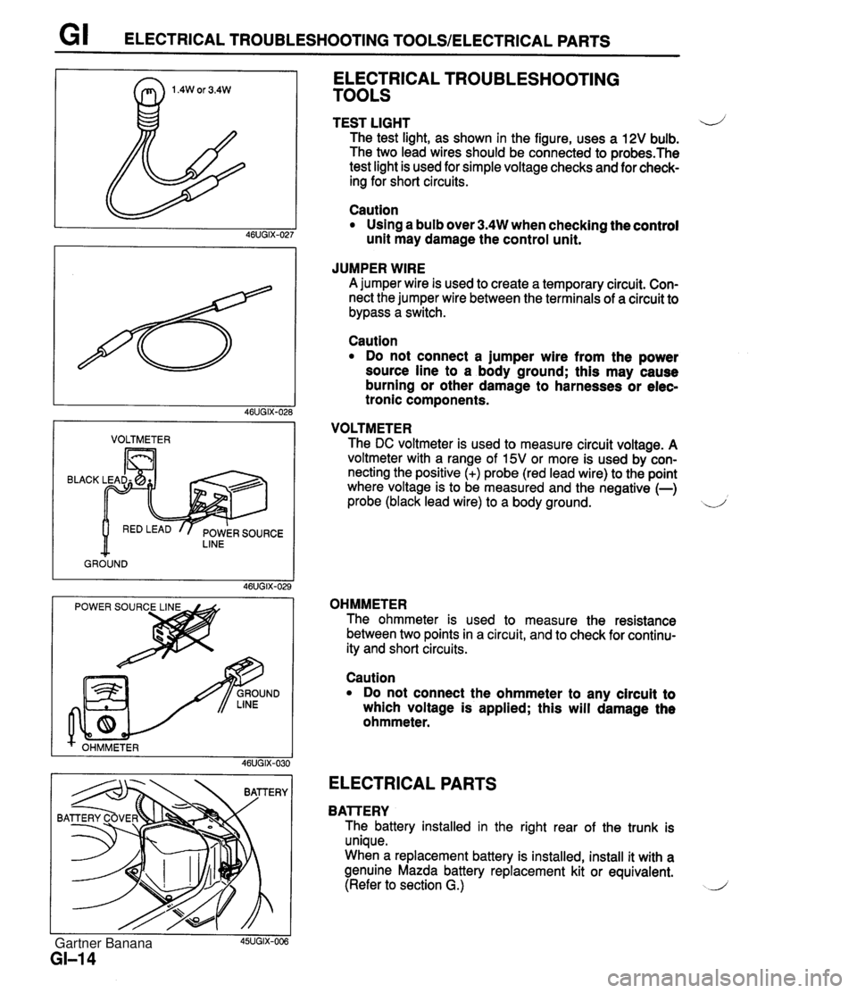
G I ELECTRICAL TROUBLESHOOTING TOOLSIELECTRICAL PARTS I VOLTMETER I BLACK LINE GROUND ELECTRICAL TROUBLESHOOTING TOOLS TEST LIGHT 4) The test light, as shown in the figure, uses a 12V bulb. The two lead wires should be connected to probes.The test light is used for simple voltage checks and for check- ing for short circuits. Caution Using a bulb over 3.4W when checking the control unit may damage the control unit. JUMPER WIRE A jumper wire is used to create a temporary circuit. Con- nect the jumper wire between the terminals of a circuit to bypass a switch. Caution Do not connect a jumper wire from the power source line to a body ground; this may cause burning or other damage to harnesses or elec- tronic components. VOLTMETER The DC voltmeter is used to measure circuit voltage. A voltmeter with a range of 15V or more is used by con- necting the positive (+) probe (red lead wire) to the point where voltage is to be measured and the negative (-) probe (black lead wire) to a body ground. d OHMMETER The ohmmeter is used to measure the resistance between two points in a circuit, and to check for continu- ity and short circuits. I I 45UGIX-006 GI-I 4 Caution Do not connect the ohmmeter to any circuit to which voltage is applied; this will damage the ohmmeter. ELECTRICAL PARTS BAlTERY The battery installed in the right rear of the trunk is unique. When a replacement battery is installed, install it with a genuine Mazda battery replacement kit or equivalent. (Refer to section G.) J Gartner Banana
Page 17 of 1708
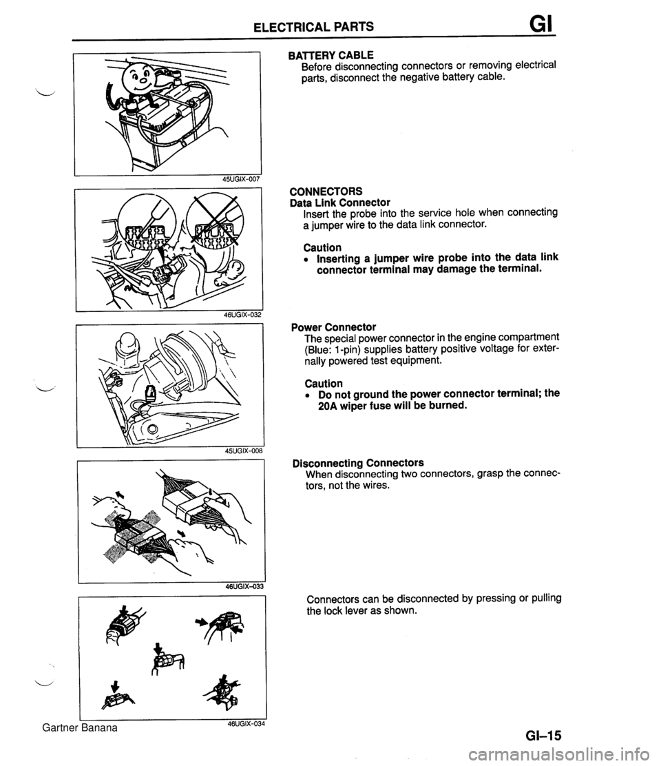
ELECTRICAL PARTS GI BATTERY CABLE Before disconnecting connectors or removing electrical parts, disconnect the negative battery cable. CONNECTORS Data Link Connector Insert the probe into the service hole when connecting a jumper wire to the data link connector. Caution Inserting a jumper wire probe into the data link connector terminal may damage the terminal. Power Connector The special power connector in the engine compartment (Blue: 1 -pin) supplies battery positive voltage for exter- nally powered test equipment. Caution Do not ground the power connector terminal; the 20A wiper fuse will be burned. Disconnecting Connectors When disconnecting two connectors, grasp the connec- tors, not the wires. Connectors can be disconnected by pressing or pulling the lock lever as shown. Gartner Banana
Page 19 of 1708
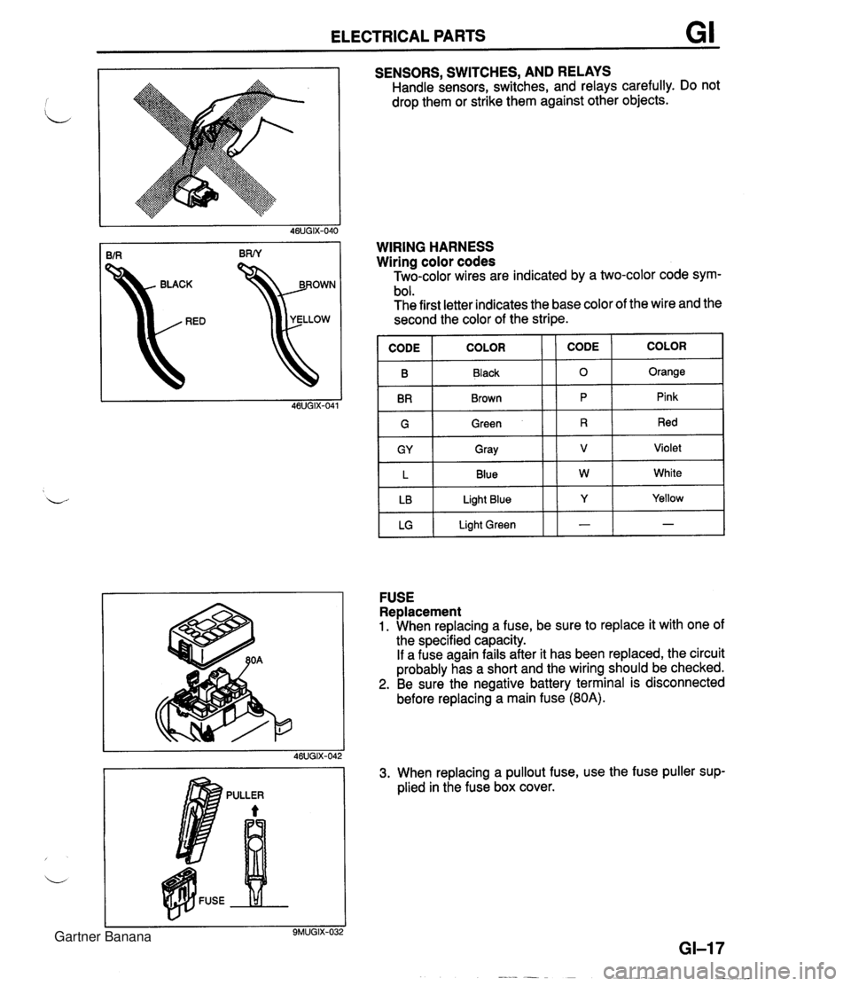
ELECTRICAL PARTS GI SENSORS, SWITCHES, AND RELAYS Handle sensors, switches, and relays carefully. Do not drop them or strike them against other objects. kD YELLOW WIRING HARNESS Wiring color codes Two-color wires are indicated by a two-color code sym- bol. The first letter indicates the base color of the wire and the second the color of the stripe. IGI Green 11 R 1 Red I B BR COLOR FUSE Replacement 1. When replacing a fuse, be sure to replace it with one of the specified capacity. If a fuse again fails after it has been replaced, the circuit probably has a short and the wiring should be checked. 2. Be sure the negative battery terminal is disconnected before replacing a main fuse (80A). CODE CODE Black Brown GY L LB LG 3. When replacing a pullout fuse, use the fuse puller sup- plied in the fuse box cover. COLOR 0 P Gray Blue Light Blue Light Green Orange Pink V W Y - Violet White Yellow - Gartner Banana
Page 20 of 1708

G I INSTALLATION OF MOBILE TWO-WAY RADIO SYSTEMIAUDIO ANTITHEFT SYSTEM INSTALLATION OF MOBILE TWO-WAY RADIO SYSTEM If a mobile two-way radio system is installed improperly or if a high-powered type is used, the CIS and other systems may be affected. L-.) When the vehicle is to be equipped with a mobile two-way radio, observe the following precautions: 1. lnstall the antenna at the farthest point from control units. 2. Install the antenna feeder as far as possible from the control unit harnesses (at least 30 cm (11.8 in)). 3. Ensure that the antenna and feeder are properly adjusted. 4. Do not install a hiah-h owe red mobile two-wav radio svstem. FEEDER W!RE CONTROL UNIT HARNESS AT LEAST 30 cm (11.8 in) 46UGIX-043 AUDIO ANTITHEFT SYSTEM An audio with an antitheft function is optionally available. Before removing the negative battery terminal or discon- necting the audio power source, obtain the code number and deactivate the audio antitheft system. (Refer to section T.) Gartner Banana
Page 23 of 1708
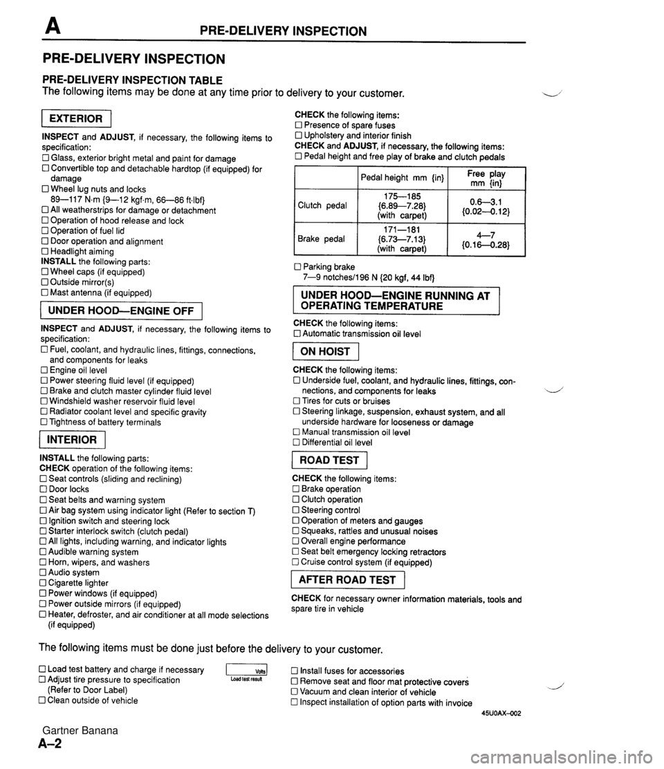
PRE-DELIVERY INSPECTION PRE-DELIVERY INSPECTION PRE-DELIVERY INSPECTION TABLE The following items may be done at any time prior to delivery to your customer. INSPECT and ADJUST, if necessary, the following items to specification: 0 Glass, exterior bright metal and paint for damage 0 Convertible top and detachable hardtop (if equipped) for damage 0 Wheel lug nuts and locks 89-117 N.m (9-1 2 kgf.m, 66-86 ft4bf) 0 All weatherstrips for damage or detachment Operation of hood release and lock Operation of fuel lid 0 Door operation and alignment Headlight aiming INSTALL the following parts: Wheel caps (if equipped) 0 Outside mirror(s) 0 Mast antenna (if equipped) UNDER HOOD-ENGINE OFF INSPECT and ADJUST, if necessary, the following items to specification : Fuel, coolant, and hydraulic lines, fittings, connections, and components for leaks Engine oil level 0 Power steering fluid level (if equipped) Brake and clutch master cylinder fluid level 0 Windshield washer reservoir fluid level 0 Radiator coolant level and specific gravity 0 Tightness of battery terminals pKiq INSTALL the following parts: CHECK operation of the following items: 0 Seat controls (sliding and reclining) 0 Door locks 0 Seat belts and warning system 0 Air bag system using indicator light (Refer to section T) Ignition switch and steering lock 0 Starter interlock switch (clutch pedal) All lights, including warning, and indicator lights 0 Audible warning system 0 Horn, wipers, and washers Audio system 0 Cigarette lighter Power windows (if equipped) 0 Power outside mirrors (if equipped) 0 Heater, defroster, and air conditioner at all mode selections (if equipped) CHECK the following items: Presence of spare fuses 0 Upholstery and interior finish CHECK and ADJUST, if necessary, the following items: 0 Pedal height and free play of brake and clutch pedals I Pedal height mm {in} I Ft: $iy I Clutch pedal {6.89--7.28) (with carpet) Parking brake 7-9 notchesil96 N (20 kgf, 44 Ibf) 0.63.1 (0.024. 12) Brake pedal RUNNING AT OPERATING TEMPERATURE CHECK the following items: 0 Automatic transmission oil level 171-181 (6.73--7.13) (with carpet) I ON HOIST I 4--7 {0.16-0.28} CHECK the following items: 0 Underside fuel, coolant, and hydraulic lines, fittings, con- nections, and components for leaks 4 Tires for cuts or bruises 0 Steering linkage, suspension, exhaust system, and all underside hardware for looseness or damage Manual transmission oil level Differential oil level I ROAD TEST I CHECK the following items: Brake operation Clutch operation 0 Steering control 0 Operation of meters and gauges Squeaks, rattles and unusual noises 0 Overall engine performance Seat belt emergency locking retractors 0 Cruise control system (if equipped) I AFTER ROAD TEST I CHECK for necessary owner information materials, tools and spare tire in vehicle The following items must be done just before the delivery to your customer. 0 Load test battery and charge if necessary -1 Install fuses for accessories Adjust tire pressure to specification Load test fesuk 0 Remove seat and floor mat protective covers (Refer to Door Label) 0 Vacuum and clean interior of vehicle Clean outside of vehicle Inspect installation of option parts with invoice 45UOAX-002 Gartner Banana
Page 47 of 1708

COMPRESSION COMPRESSION If the engine exhibits low power, poor fuel economy, or poor idle, check the following: 1. Ignition system (Refer to section G.) 2. Compression (Refer to page B-10.) 3. Fuel system (Refer to section F.) INSPECTION 1. Check that the battery is fully charged. Recharge it if necessary. (Refer to section G.) 2. Warm up the engine to the normal operating tempera- ture. 3. Turn the engine OFF. 4. Remove all spark plugs. 5. Disconnect the ignition coil connector. 6. Connect a compression gauge to the No.1 spark plug hole. 7. Fully depress the accelerator pedal and crank the en- gine. 8. Record the maximum gauge reading. 9. Check each cylinder, as above. Compression: 1,255 kPa (1 2.8 kgf/cm2, 182 psi)-300 rpm Minimum: 883 kPa (9.0 kgf/cm2, 128 psiF300 rpm Differential limit between cylinders: 196 kPa (2.0 kgf/cm2, 28 psi} 10. If the compression in one or more cylinders is low, pour a small amount of engine oil into the cylinder and re- check the compression. (1) If the compression increases, the piston, piston rings, or cylinder wall may be worn. (2) If the compression stays low, the valve may be stuck or seated improperly. (3) If the compression in adjacent cylinders stays low, the cylinder head gasket may be defective or the cyl- inder head distorted. 11 . Connect the ignition coil connector. 12. Install the spark plugs. Tightening torque: 15--22 N.m (1.5-2.3 kgf.m, 11-16 ftlbf) Gartner Banana
Page 49 of 1708

B ON-VEHICLE MAINTENANCE TIMING BELT Removal / lnstallation 1. Disconnect the negative battery cable. 2. Drain the engine coolant. 3. Remove the under cover. 4. Remove in the order shown in the figure, referring to Removal Note. 5. Install in the reverse order of removal, referring to lnstallation Note. (80-110 kgfmn, 7.9-10.7 Nm 13-17 Nm (125-175 kgfcm, 109-151 In4bf) Nm (kgfm, ft4bf) 45UOBX425 1. Air intake pipe 12. Spark plug 2. Upper radiator hose Removal / Installation ......... section G 3. Water hoses (Connected to thermostat 13. PCV valve housing) 14. Cylinder head cover 4. PIS andlor A/C drive belt 15. Upper timing belt cover Removal 1 Installation ....... page B- 6 16. Middle timing belt cover 5. Alternator drive belt 17. Lower timing belt cover Removal / Installation ....... page 5 6 18. Timing belt 6. Water pump pulley Removal Note ............. page B-13 7. Plate Installation Note ........... page B-14 8. Crankshaft pulley Inspection ................. page 8-58 9. Pulley lock bolt 19. Tensioner, tensioner spring Removal Note ............. page B-13 Installation Note ........... page B-14 /' Installation Note ........... page 51 5 Inspection ................. page 558 10. Pulley boss 20. Idler 11. Ignition coil and high-tension lead Inspection ................. page 8-58 Gartner Banana
Page 52 of 1708

ON-VEHICLE MAINTENANCE B Stem After Installation 10. Loosen the tensioner lock bolt to apply spring tension to the timing belt. 11. Tighten the tensioner lock bolt. Tightening torque: 38-51 N-m (3.8-5.3 kgf.m, 28--38 ftlbf) 12. Install the pulley boss and pulley lock bolt. 13. Turn the crankshaft 2 and 116 turns clockwise and verify that the timing marks are correctly aligned. 14. Measure the timing belt deflection by applying moderate pressure 98 N (10 kgf, 22 Ibf) midway between the cam- shaft pulleys. If the deflection is not correct, repeat from Step 10 above. Deflection: 9.0-11.5mm (0.36-4.45 in) at 98 N (10 kgf, 22 Ibf) Pulley lock bolt Hold the crankshaft with the SST and tighten the pulley lock bolt. Tightening torque: 157-166 N.m (16-17 kgf.m, 116-122 ftlbf) 1. till the radiator with specified amount and type of engine coolant. (Refer to section E.) 2. Connect the negative battery cable. 3. Start the engine and check, and if necessary, adjust the ignition timing. Gartner Banana