ignition MAZDA MX-5 1994 Workshop Manual
[x] Cancel search | Manufacturer: MAZDA, Model Year: 1994, Model line: MX-5, Model: MAZDA MX-5 1994Pages: 1708, PDF Size: 82.34 MB
Page 9 of 1708
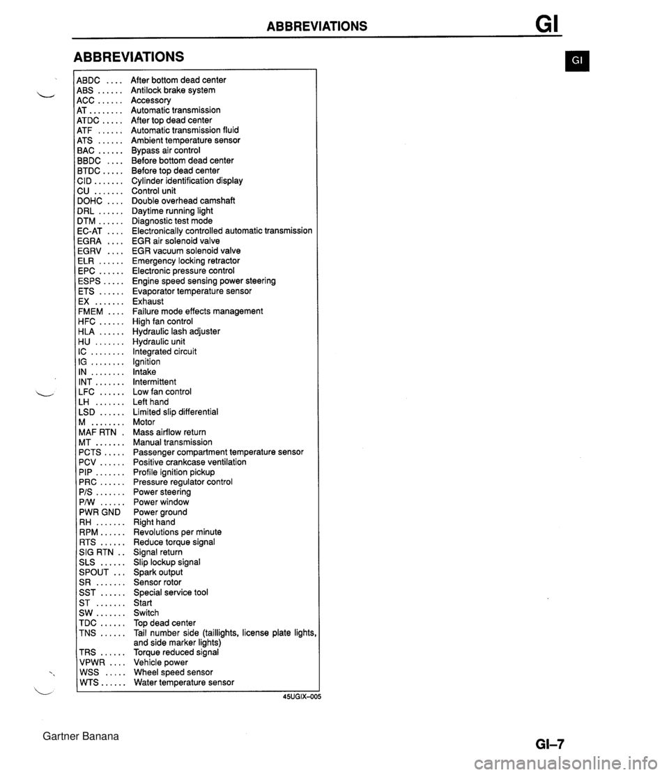
ABBREVIATIONS 4BDC .... 4BS ...... 4CC ...... 4T ........ 4TDC ..... 4TF ...... 4TS ...... 3AC ...... 3BDC .... 3TDC ..... :ID ....... 2U ....... IOHC .... IRL ...... ITM ...... IC-AT .... iGRA .... EGRV .... ELR ...... EPC ...... ESPS ..... ETS ...... EX ....... FMEM .... HFC ...... HLA ...... H U ....... IC ........ IG ........ IN ........ INT ....... LFC ...... LH ....... LSD ...... M ........ MAF RTN . MT ....... PCTS ..... PCV ...... PIP ....... PRC ...... PIS ....... PMI ...... PWR GND RH ....... RPM ...... RTS ...... SIG RTN . . SLS ...... ... SPOUT S R ....... SST ...... ST ....... SW ....... TDC ...... TNS ...... TRS ...... VPWR .... WSS ..... WTS...... After bottom dead center Antilock brake system Accessory Automatic transmission After top dead center Automatic transmission fluid Ambient temperature sensor Bypass air control Before bottom dead center Before top dead center Cylinder identification display Control unit Double overhead camshaft Daytime running light Diagnostic test mode Electronically controlled automatic transmission EGR air solenoid valve EGR vacuum solenoid valve Emergency locking retractor Electronic pressure control Engine speed sensing power steering Evaporator temperature sensor Exhaust Failure mode effects management High fan control Hydraulic lash adjuster Hydraulic unit Integrated circuit Ignition Intake Intermittent Low fan control Left hand Limited slip differential Motor Mass airflow return Manual transmission Passenger compartment temperature sensor Positive crankcase ventilation Profile ignition pickup Pressure regulator control Power steering Power window Power ground Right hand Revolutions per minute Reduce torque signal Signal return Slip lockup signal Spark output Sensor rotor Special service tool Start Switch Top dead center Tail number side (taillights, license plate lights and side marker lights) Torque reduced signal Vehicle power Wheel speed sensor Water temperature sensor Gartner Banana
Page 10 of 1708
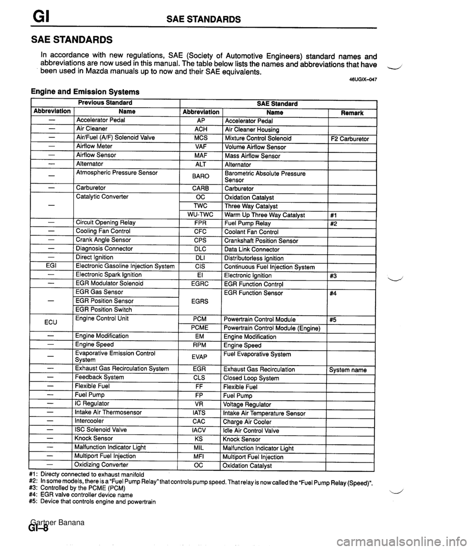
SAE STANDARDS SAE STANDARDS In accordance with new regulations, SAE (Society of Automotive Engineers) standard names and abbreviations are now used in this manual. The table below lists the names and abbreviations that have 4 been used in Mazda manuals up to now and their SAE equivalents. 46UGIX-047 Engine and Emission Systems Accelerator Pedal Air Cleaner Housing I Mixture Control Solenoid I F2 Carburetor ] Abbreviation AP ACH MCS VAF M AF Abbreviation - - - - - Volume Airflow Sensor I I Name Accelerator Pedal Air Cleaner AirlFuel (NF) Solenoid Valve Airflow Meter Airflow Sensor I Mass Airflow Sensor I I Alternator I I - - - -~ I Barometric Absolute Pressure I I Sensor I I Alternator Atmospheric Pressure Sensor I - 1 Carburetor CARB 1 Catalytic Converter OC ALT BAR0 Carburetor 1 Oxidation Catalvst I - - - - - I Direct Ignition I DL1 EG I 1 Electronic Gasoline lniection Svstem I CIS Three Way Catalyst Warm Up Three Way Catalyst Fuel Pump Relay Coolant Fan Control Crankshaft Position Sensor Data Link Connector Circuit Opening Relay Cooling Fan Control Crank Angle Sensor Diaanosis Connector Distributorless Ignition I Continuous Fuel lniection Svstem I 1 #1 #2 FPR C FC CPS DLC I Previous Standard SAE Standard Name I Remark - ( Electronic Spark Ignition EGR Gas Sensor EGR Position Sensor EGR Position Switch El Electronic Ignition 1 #3 EGR Function Control I - I EGR Modulator Solenoid I EGRC 4 ECU I Evaporative Emission Control Svstem I EVAP - - I -,--- I - I Exhaust Gas Recirculation System I EGR Engine Control Unit PCM PCME Engine Modification Ennine Speed EM RPM - - - - - Feedback System Flexible Fuel - I Intercooler Powertrain Control Module I #5 I EGR Function Sensor CLS FF Fuel Pump IC Regulator Intake Air Thermosensor CAC I Powertrain Control Module (Engine) I #4 FP VR IATS - I ISC Solenoid Valve I IACV Engine Modification I Engine Speed - Fuel Evaporative System I Exhaust Gas Recirculation 1 System name 1 Closed Loop System I Flexible Fuel Knock Sensor I I - ( Knock Sensor I KS I Malfunction Indicator Light I I - I Malfunction Indicator Liaht MIL Multiport Fuel Injection Oxidation Catalyst - 1 Multiport Fuel Injection #1: Directy connected to exhaust manifold #2: In some models, there is a "Fuel Pump Relay" that controls pump speed. That relay is now called the 'Fuel Pump Relay (Speed)". #3: Controlled by the PCME (PCM) 4 #4: EGR valve controller device name #5: Device that controls engine and powertrain MFI - 1 Oxidizina Converter OC Gartner Banana
Page 11 of 1708
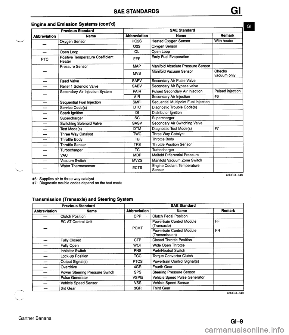
SAE STANDARDS Engine and Emission Systems (cont'd) I Previous Standard I SAE Standard b I - Abbreviation ( Name I Oxvaen Sensor - .w- - I I ." I 02s I Oxygen Sensor I - PTC Reed Valve Relief 1 Solenoid Valve Secondary Air lnjection System - Seauential Fuel lniection SMFl L - Service Code(s) DTC - Spark Ignition Dl - Supercharger SC Abbreviation I Name Open Loop Positive Temperature Coefficient Hnatar Secondarv Air Pulse Valve Remark . .--.-. Pressure Sensor Secondary Air Bypass valve Pulsed Secondarv Air lniection H02S I Heated Oxvaen Sensor I With heater OL EFE Secondary Air lnjection Sequential Multipoint Fuel lnjection Diagnostic Trouble Code(s) Open Loop Early Fuel Evaporation MAP MVS Distributor lgnition Supercharger Manifold Absolute Pressure Sensor Manifold Vacuum Sensor I - - - - - - Checks vacuum only Pulsed iniection - Switching Solenoid Valve Test Mode(s) Three Way Catalyst Throttle Body Throttle Sensor Turbocharaer .. Maifold Differential Pressure Manifold Vacuum Zone Switch , - I - 1 VAC I MDP 1-1 Water Thermosensor L - I Vacuum Switch I ECTS I Engine Coolant Temperature Sensor I SASV DTM TWC TB TPS TC MVZS #6: Supplies air to three way catalyst #7: Diagnostic trouble codes depend on the test mode - Secondary Air Switching Valve Diagnostic Test Mode(s) Three Way Catalyst Throttle Body Throttle Position Sensor Turbocharaer Transmission (Transaxle) and Steering System L - - Previous Standard I I I I Abbreviation - - - SAE Standard Fully Open Inhibitor Switch - I Lock-up Position - - Name Clutch Position EC-AT Control Unit Fullv Closed Abbreviation CPP PCMT CTP TCC I Torque Converter Clutch - - - WOT PNS Output Signal(s) Overdrive I Name Clutch Pedal Position Powertrain Control Module (Transaxle) Powertrain Control Module (Transmission) Closed Throttle Position Wide Open Throttle ParWNeutral Switch Power Steering Pressure Switch Pulse Generator Vehicle Speed Sensor - 1 3rd Gear Remark FF FR PTCS 4GR 3GR I Third Gear Powertrain Control Signal(@ Fourth Gear SPS VSPG VSS Steering Pressure Sensor Vehicle Speed Pulse Generator Vehicle Speed Sensor Gartner Banana
Page 21 of 1708
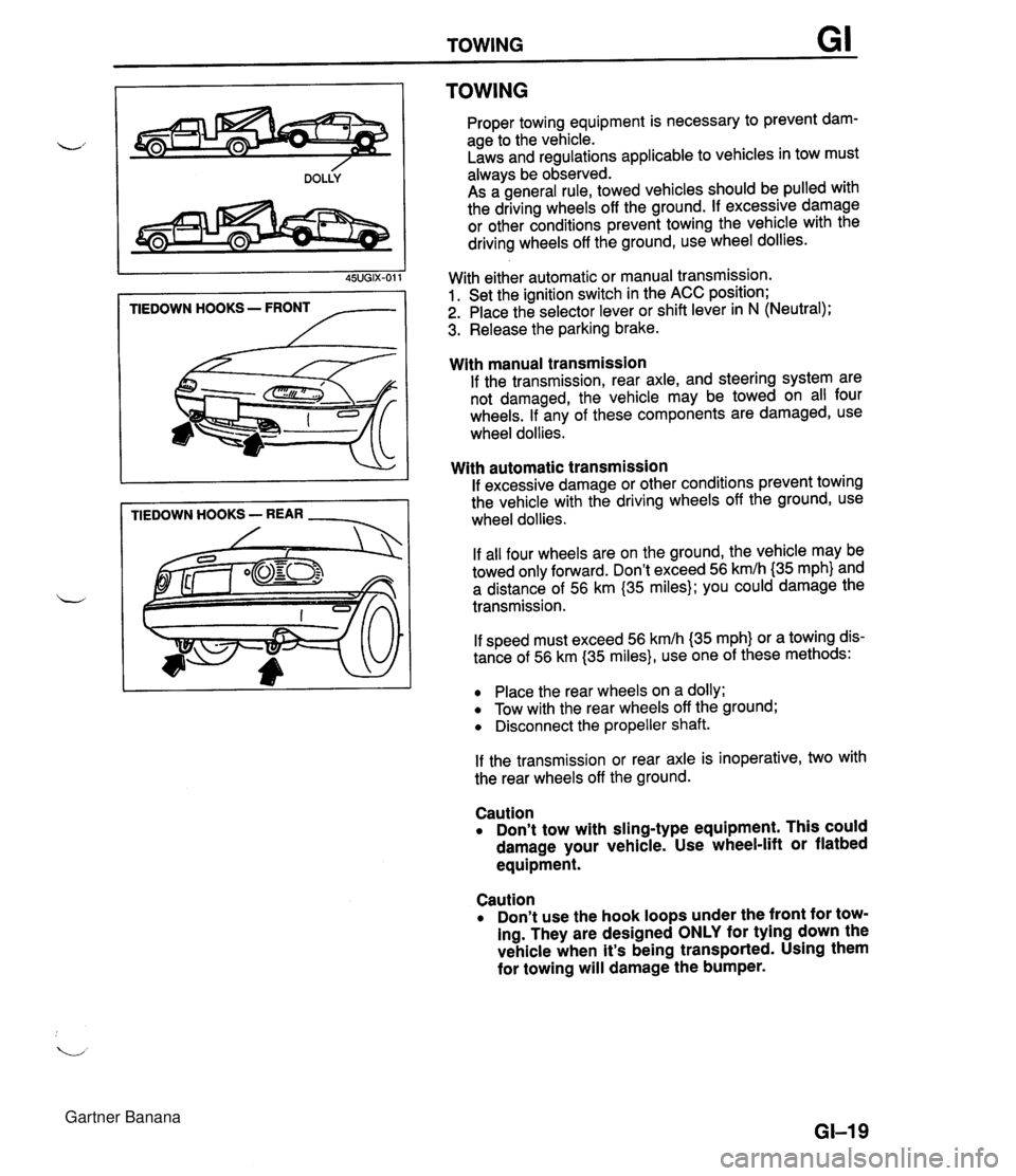
TOWING TIEDOWN HOOKS - FRONT /-- TIEDOWN HOOKS - REAR - TOWING Proper towing equipment is necessary to prevent dam- age to the vehicle. Laws and regulations applicable to vehicles in tow must always be observed. As a general rule, towed vehicles should be pulled with the driving wheels off the ground. If excessive damage or other conditions prevent towing the vehicle with the driving wheels off the ground, use wheel dollies. With either automatic or manual transmission. 1. Set the ignition switch in the ACC position; 2. Place the selector lever or shift lever in N (Neutral); 3. Release the parking brake. With manual transmission If the transmission, rear axle, and steering system are not damaged, the vehicle may be towed on all four wheels. If any of these components are damaged, use wheel dollies. With automatic transmission If excessive damage or other conditions prevent towing the vehicle with the driving wheels off the ground, use wheel dollies. If all four wheels are on the ground, the vehicle may be towed only forward. Don't exceed 56 kmlh {35 mph} and a distance of 56 km (35 miles); you could damage the transmission. If speed must exceed 56 kmlh (35 mph} or a towing dis- tance of 56 km (35 miles}, use one of these methods: Place the rear wheels on a dolly; Tow with the rear wheels off the ground; Disconnect the propeller shaft. If the transmission or rear axle is inoperative, two with the rear wheels off the ground. Caution Don't tow with sling-type equipment. This could damage your vehicle. Use wheel-lift or flatbed equipment. Caution Don't use the hook loops under the front for tow- ing. They are designed ONLY for tying down the vehicle when it's being transported. Using them for towing will damage the bumper. GI-I 9 Gartner Banana
Page 23 of 1708
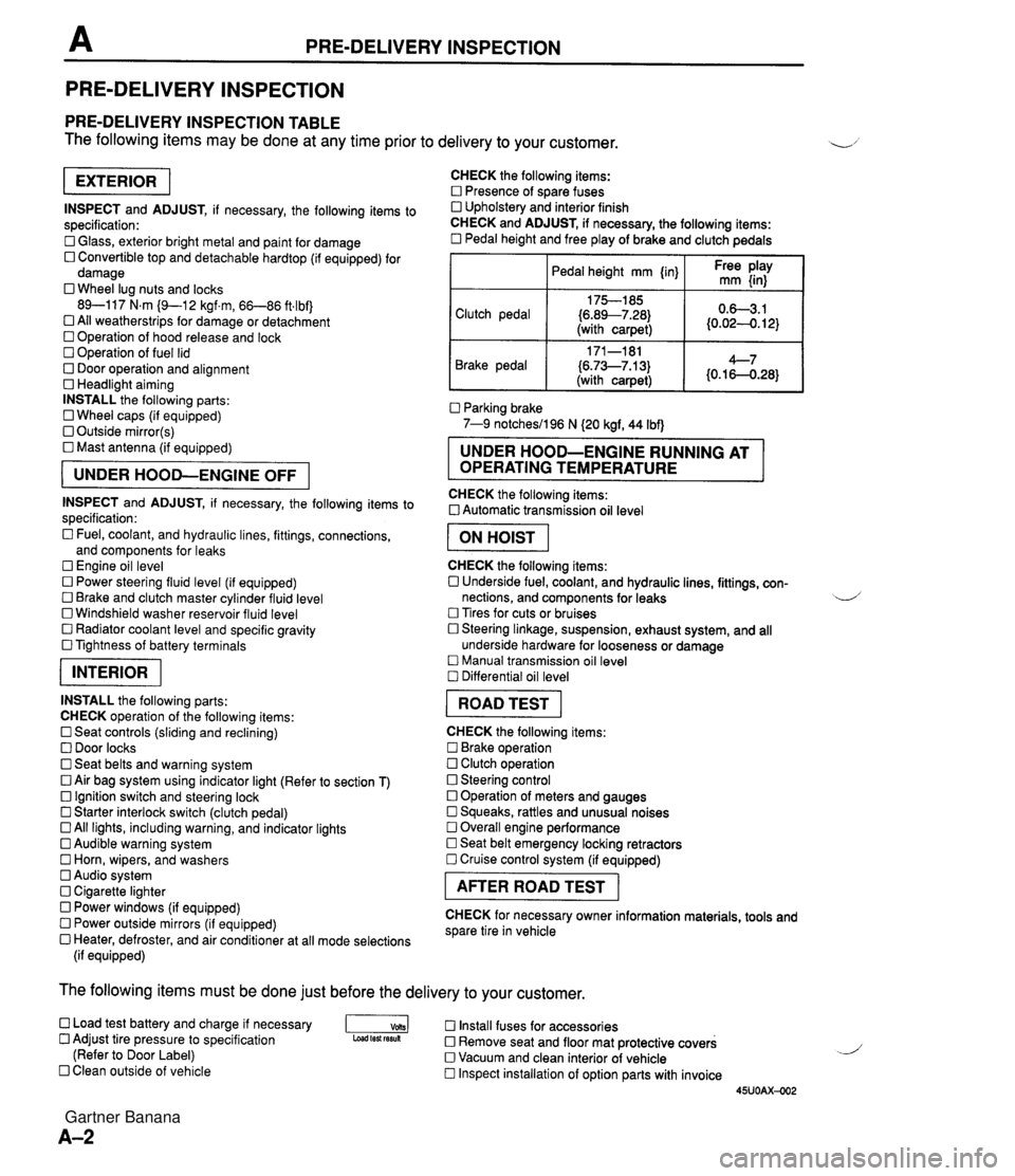
PRE-DELIVERY INSPECTION PRE-DELIVERY INSPECTION PRE-DELIVERY INSPECTION TABLE The following items may be done at any time prior to delivery to your customer. INSPECT and ADJUST, if necessary, the following items to specification: 0 Glass, exterior bright metal and paint for damage 0 Convertible top and detachable hardtop (if equipped) for damage 0 Wheel lug nuts and locks 89-117 N.m (9-1 2 kgf.m, 66-86 ft4bf) 0 All weatherstrips for damage or detachment Operation of hood release and lock Operation of fuel lid 0 Door operation and alignment Headlight aiming INSTALL the following parts: Wheel caps (if equipped) 0 Outside mirror(s) 0 Mast antenna (if equipped) UNDER HOOD-ENGINE OFF INSPECT and ADJUST, if necessary, the following items to specification : Fuel, coolant, and hydraulic lines, fittings, connections, and components for leaks Engine oil level 0 Power steering fluid level (if equipped) Brake and clutch master cylinder fluid level 0 Windshield washer reservoir fluid level 0 Radiator coolant level and specific gravity 0 Tightness of battery terminals pKiq INSTALL the following parts: CHECK operation of the following items: 0 Seat controls (sliding and reclining) 0 Door locks 0 Seat belts and warning system 0 Air bag system using indicator light (Refer to section T) Ignition switch and steering lock 0 Starter interlock switch (clutch pedal) All lights, including warning, and indicator lights 0 Audible warning system 0 Horn, wipers, and washers Audio system 0 Cigarette lighter Power windows (if equipped) 0 Power outside mirrors (if equipped) 0 Heater, defroster, and air conditioner at all mode selections (if equipped) CHECK the following items: Presence of spare fuses 0 Upholstery and interior finish CHECK and ADJUST, if necessary, the following items: 0 Pedal height and free play of brake and clutch pedals I Pedal height mm {in} I Ft: $iy I Clutch pedal {6.89--7.28) (with carpet) Parking brake 7-9 notchesil96 N (20 kgf, 44 Ibf) 0.63.1 (0.024. 12) Brake pedal RUNNING AT OPERATING TEMPERATURE CHECK the following items: 0 Automatic transmission oil level 171-181 (6.73--7.13) (with carpet) I ON HOIST I 4--7 {0.16-0.28} CHECK the following items: 0 Underside fuel, coolant, and hydraulic lines, fittings, con- nections, and components for leaks 4 Tires for cuts or bruises 0 Steering linkage, suspension, exhaust system, and all underside hardware for looseness or damage Manual transmission oil level Differential oil level I ROAD TEST I CHECK the following items: Brake operation Clutch operation 0 Steering control 0 Operation of meters and gauges Squeaks, rattles and unusual noises 0 Overall engine performance Seat belt emergency locking retractors 0 Cruise control system (if equipped) I AFTER ROAD TEST I CHECK for necessary owner information materials, tools and spare tire in vehicle The following items must be done just before the delivery to your customer. 0 Load test battery and charge if necessary -1 Install fuses for accessories Adjust tire pressure to specification Load test fesuk 0 Remove seat and floor mat protective covers (Refer to Door Label) 0 Vacuum and clean interior of vehicle Clean outside of vehicle Inspect installation of option parts with invoice 45UOAX-002 Gartner Banana
Page 32 of 1708
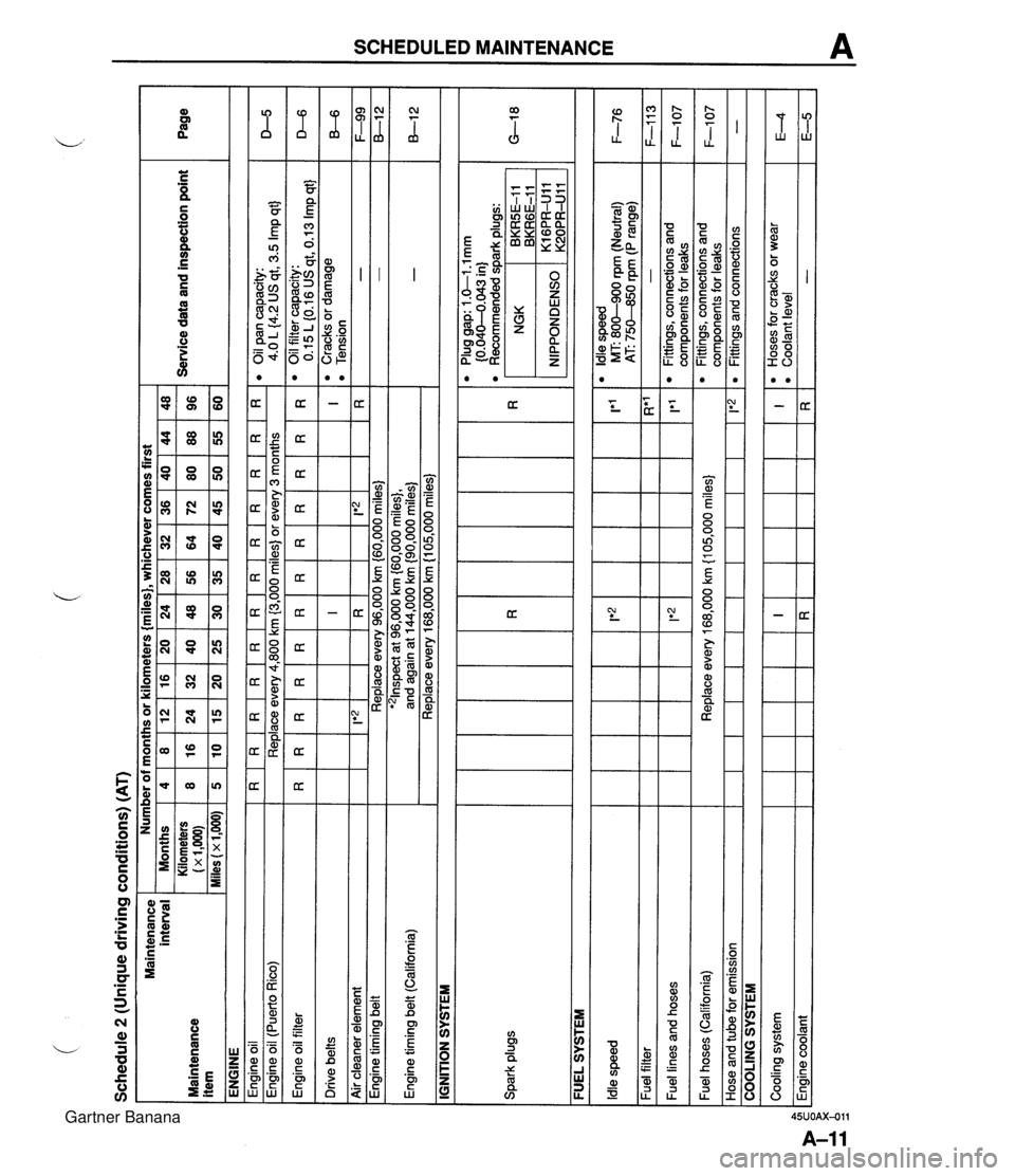
Schedule 2 (Unique driving conditions) (AT) Maintenance interval Maintenance item ENGINE Engine oil I R I R I R I R I R I R I R I R I R I R I R I R Engine oil filter Drive belts Number of months or kilometers {miles}, whichever comes first eoilpancapacity: 4.0 L {4.2 US qt, 3.5 Imp qt} Engine oil (Puerto Rico) I I IGNITION SYSTEM Service data and inspection point Months Kilometers (x 1,m) Miles (x 1,000) D-5 Replace every 4,800 km (3,000 miles) or every 3 months I I I I I I I I - - Engine timing belt (California) Spark plugs Page - - Air cleaner element I I FUEL SYSTEM 4 8 5 I F-99 8-1 2 -. . . '21nspect at 96,000 km {60,000 miles}, and again at 144,000 km {90,000 miles) Replace every 168,000 km (1 05,000 miles) - - R*' - 1'1 l Oilfiltercapacity: 0.15 L (0.16 US qt, 0.13 Imp qt} l Cracks or damage l Tension I R 1 Ie2 1 Engine timing belt ~ --- - - l Plug gap: 1 .&I -1 mm (0.040-4.043 in) l Recommended dark ~luas: 8 16 10 D-6 B-6 Replace every 96,000 km (60,000 miles) Idle speed Fuel filter Fuel lines and hoses NGK , BKRGE-11 BKR5E-I 1 12 24 15 IRI I*2 lt2 l Idle speed MT: 800-900 rpm (Neutral) 1 F-76 AT: 75M0 rpm (P range) 16 32 20 I!*'2 1 20 40 25 24 48 30 - Fittings, connections and com~onents for leaks 36 72 45 F-113 F-1 07 Fuel hoses (California) Hose and tube for emission 28 56 35 Cooling system Engine coolant 32 64 40 COOLING SYSTEM Replace every 168,000 km {I 05,000 miles} 1 1*2 48 96 60 40 80 50 I R 44 88 55 l Fittings, connections and components for leaks Fittings and connections F-1 07 - I R l Hoses for cracks or wear l Coolant level - E4 E-5 Gartner Banana
Page 35 of 1708
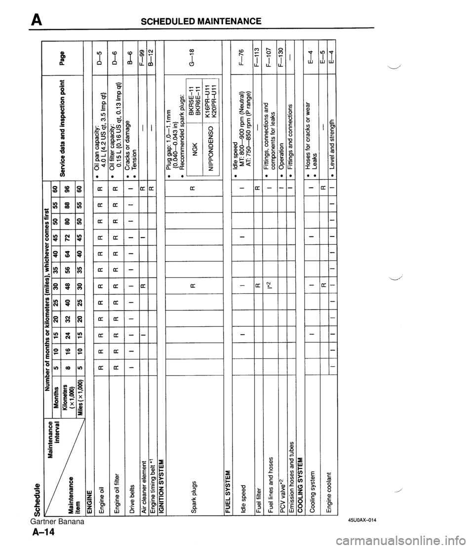
Schedule interval Maintenance ENGINE Number of months or kilometers {miles), whichever comes first I -. Months 5 10 15 20 25 30 35 40 45 50 55 60 Kilometers 8 16 24 32 40 48 56 64 72 80 88 96 - Service data and inspection point 1~1.000~ Page Spark plugs FUEL SYSTEM -- Plug gap: 1 .GI .l mm {0.04M.043 in) l Recommended spark plugs: D-5 D-6 B-6 F-99 8-1 2 IGNITION SYSTEM R I I Engine oil Engine oil filter Drive belts Air cleaner element Engine timing belt 'l R I R I F-76 F-1 1 3 F-107 F-I30 - Idle speed Fuel filter Fuel lines and hoses PCV valve'2 Emission hoses and tubes R I COOLING SYSTEM I Cooling system Engine coolant R I R I I E4 E-5 E4 I R I R I R I R I*z I l Hoses for cracks or wear l Leaks - Level and strength I R RR I R R R I I R I OilPancapacity: 4.0 L (4.2 US qt, 3.5 Imp qt) 0 Oil filter capacity: 0.15L(0.16USqt,0.13Impqt) 'Cracksordamage 0 Tension - - R I I I I I R I l ldle speed MT: 800-900 rpm (Neutral) AT 750-850 rpm (P range) - l Fittings, connections and components for leaks Operation Fittings and connections I I R I I I I I I I I I R I Gartner Banana
Page 38 of 1708

Before beginning any service procedure. refer to section T of this manual for air bag system service warnings and audio antitheft system alarm conditions . ENGINE INDEX ............................. B- 2 OUTLINE .......................... B- 3 SPECIFICATIONS ................ B- 3 TROUBLESHOOTING GUIDE ........ B- 3 ENGINE TUNE-UP .................. 8- 5 PREPARATION ................... B- 5 ENGINE OIL ..................... B- 5 ENGINE COOLANT ............... B- 5 DRIVE BELT ..................... 8- 6 HLA TROUBLESHOOTING GUIDE . 8- 8 IGNITION TIMING. IDLE SPEED .... B- 8 COMPRESSION .................... 8-10 INSPECTION ..................... B-10 ON-VEHICLE MAINTENANCE ....... B-11 PREPARATION ................... B-11 TIMING BELT ..................... 8-12 CYLINDER HEAD GASKET ........ B-16 H LA ............................. 8-20 FRONT OIL SEAL ................. 8-24 REAR OIL SEAL .................. 8-26 REMOVAL ......................... 8-28 PROCEDURE .................... B-28 ENGINE STAND MOUNTING ......... 8-32 PREPARATION ................... 8-32 PROCEDURE .................... B-33 DISASSEMBLY ..................... B-35 PREPARATION ................... 8-35 AUXILIARY PARTS ............... 8-36 TIMING BELT ..................... 8-37 CYLINDER HEAD ................. 8-39 CYLINDER BLOCK (EXTERNAL PARTS) ............. 8-42 CYLINDER BLOCK .............. (INTERNAL PARTS) 8-44 .............. INSPECTION I REPAIR 8-47 ................... PREPARATION 8-47 ................. CYLINDER HEAD 8-47 .............. VALVE MECHANISM 8-48 ...................... CAMSHAFT B-51 HLA ............................. 8-53 ............... CYLINDER BLOCK B-53 .......................... OIL JET B-54 PISTON. PISTON RING. AND ..................... PISTON PIN 8-55 CONNECTING ROD .............. B-56 ................... CRANKSHAFT 8-57 BEARING ........................ 8-57 TIMING BELT ..................... 8-58 TENSIONER. IDLER .............. 8-58 TENSIONER SPRING ............. 8-58 PULLEY ......................... 8-58 ........................ ASSEMBLY 8-59 ................... PREPARATION 8-59 CYLINDER BLOCK (INTERNAL PARTS) .............. B-60 CYLINDER BLOCK (EXTERNAL PARTS) ............. B-65 CYLINDER HEAD ................. B-69 TIMING BELT ..................... 8-73 ............... AUXILIARY PARTS 8-77 ..... ENGINE STAND DISMOUNTING 8-81 .................... PROCEDURE 8-81 INSTALLATION ..................... 8-83 .................... PROCEDURE 843 45UOBX-001 Gartner Banana
Page 40 of 1708
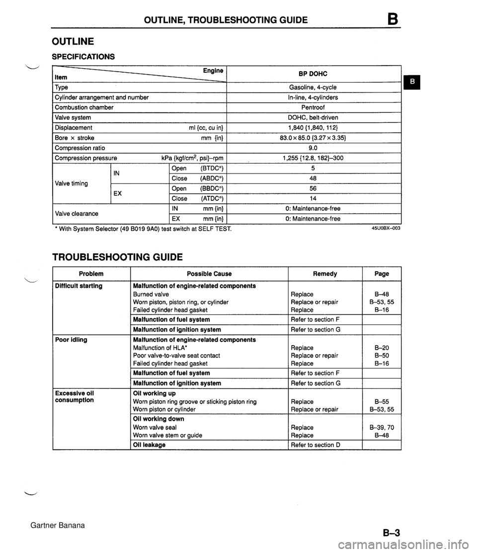
OUTLINE, TROUBLESHOOTING GUIDE OUTLINE SPECIFICATIONS Engine Item Tv~e BP DOHC Gasoline, 4-cvcle . . I -, Dis~lacement ml kc. cu inl I 1.840 (1.840. 11 2) I Cylinder arrangement and number Combustion chamber Valve system Bore x stroke mm {in) I 83.0 x 85.0 (3.27 x 3.35) I In-line, 4-cylinders Pentroof DOHC, belt-driven Com~ression ratio I 9.0 I Compression pressure kPa (kgf/cm2, psi)-rpm .- . 1 open (BTDCO) 1,255 {I 2.8, 182)-300 5 Valve timing TROUBLESHOOTING GUIDE tX Valve clearance Problem .. . -. . Difficult starting ' With System Selector (49 B019 9AO) test switch at SELF TEST. 45uo~x-003 Close (ATDCO) IN mm {in) EX mm {in) Poor idling Close (ABDCO) Open (BBDCO) 14 0: Maintenance-free 0: Maintenance-free Excessive oil consumption 48 56 Possible Cause Malfunction of engine-related components Burned valve Worn piston, piston ring, or cylinder Failed cylinder head gasket Malfunction of fuel system Malfunction of ignition system Malfunction of engine-related components Malfunction of HLA' Poor valve-to-valve seat contact Failed cvlinder head aasket Oil leakage I Refer to section D I I Remedy Malfunction of fuel system Malfunction of ignition system Oil working up Worn piston ring groove or sticking piston ring Worn piston or cylinder Oil working down Worn valve seal Worn valve stem or guide Page Replace Replace or repair Replace Refer to section F Refer to section G Replace Replace or repair Re~lace 8-48 B-53,55 B-1 6 B-20 B-50 B-1 6 Refer to section F Refer to section G Replace Replace or repair Replace Replace B-55 B-53,55 B-39,70 8-48 Gartner Banana
Page 41 of 1708

B TROUBLESHOOTING GUIDE Problem nsufficlent power 4bnormal combustion Engine noise Possible Cause Insufficient compression Malfunction of HLA' Compression leakage from valve seat Seized valve stem Weak or broken valve spring Failed cylinder head gasket Cracked or distorted cylinder head Stuck, damaged, or worn piston ring Cracked or worn piston Malfunction of fuel system Malfunction of ignition system Others Slipping clutch Dragging brakes Wrong size tires Malfunction of engine-related components Malfunction of HLA* Stuck or burned valve Weak or broken valve spring Carbon accumulation in combustion chamber Malfunction of fuel system Malfunction of ignition system Crankshaft- or bearing-related parts Excessive main bearing oil clearance Main bearing seized or heat-damaged Excessive crankshaft end play Excessive connecting rod bearing oil clearance Connecting rod bearing seized or heat-damaged Piston-related parts Worn cylinder Worn piston or piston pin Seized piston Damaged piston ring Bent connecting rod Valves or timing-related parts Malfunction of HLA' Broken valve spring Excessive valve auide clearance Malfunction of cooling system Malfunction of fuel system Others Malfunction of water pump bearing Improper drive belt tension Malfunction of alternator bearing Exhaust gas leakage Malfunction of timina belt tensioner Remedy Replace Repair Replace Replace Replace Replace Replace Replace Refer to section F Refer to section G Refer to section H Refer to section P Refer to section Q Replace Replace Replace Eliminate carbon Refer to section F Refer to section G Replace or repair Replace Replace or repair Replace or repair Replace Replace or repair Replace Replace Replace Replace Replace Replace Replace Refer to section E Refer to section F Refer to section E Adjust Refer to section G Refer to section F Replace Page Tappet noise may occur if the engine has set idle for an extended period. The noise should dissipate after the engine has reached normal operating temperature. (HLA troubleshooting: Refer to page 6-8) Gartner Banana