light MAZDA MX-5 1994 Service Manual
[x] Cancel search | Manufacturer: MAZDA, Model Year: 1994, Model line: MX-5, Model: MAZDA MX-5 1994Pages: 1708, PDF Size: 82.34 MB
Page 325 of 1708
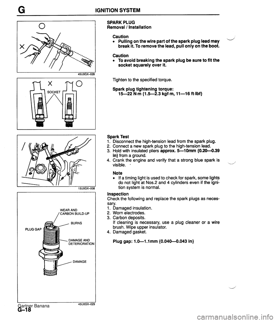
G IGNITION SYSTEM BURNS PLUG GAP DAMAGE AND DETERIORATION DAMAGE SPARK PLUG Removal 1 Installation Caution Pulling on the wire part of the spark plug lead may i/ break it. To remove the lead, pull only on the boot. Caution To avoid breaking the spark plug be sure to fit the socket squarely over it. Tighten to the specified torque. Spark plug tightening torque: 15--22 N-m (1.5--2.3 kgf-m, 11-16 ft-lbf) Spark Test 1. Disconnect the high-tension lead from the spark plug. 2. Connect a new spark plug to the high-tension lead. 3. Hold with insulated pliers approx. 5-10mm (0.20-4.39 in) from a ground. 4. Crank the engine and verify that a strong blue spark is visible. . -.d' Note If a timing light is used to check for spark, some lights do not light at Nos.:! and 4 cylinders even if the igni- tion system is normal. Inspection Check the following and replace the spark plugs as neces- sary. 1. Damaged insulation. 2. Worn electrodes. 3. Carbon deposits. If cleaning is necessary, use a plug cleaner or a wire brush. Wipe upper insulator. 4. Damaged gasket. Plug gap: 1 .O-1 .l mm (0.040-0.043 in) Gartner Banana
Page 367 of 1708
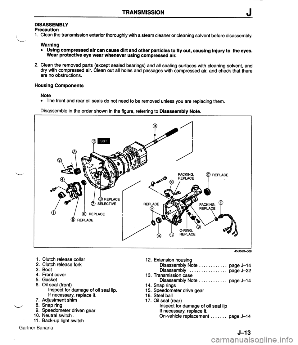
TRANSMISSION J DISASSEMBLY Precaution : 1. Clean the transmission exterior thoroughly with a steam cleaner or cleaning solvent before disassembly. b Warning Using compressed air can cause dirt and other particles to fly out, causing injury to the eyes. Wear protective eye wear whenever using compressed air. 2. Clean the removed parts (except sealed bearings) and all sealing surfaces with cleaning solvent, and dry with compressed air. Clean out all holes and passages with compressed air, and check that there are no obstructions. Housing Components Note The front and rear oil seals do not need to be removed unless you are replacing them. Disassemble in the order shown in the figure, referring to Disassembly Note. 1. Clutch release collar 2. Clutch release fork 3. Boot 4. Front cover 12. Extension housing Disassembly Note ............ page J-14 Disassembly ................ page J-22 13. Transmission case 5. Gasket Disassembly Note ............ pane J-14 6. Oil seal (front) lnspect for damage of oil seal lip. If necessary, replace it. 7. Adjustment shim 8. Snap ring 9. Speedometer driven gear 10. Neutral switch 11. Back-up light switch . - 14. Snap rings 15. Speedometer drive gear 16. Steel ball 17. Oil seal (rear) lnspect for damage of oil seal lip If necessary, replace it. On-vehicle replacement ....... page J-14 Gartner Banana
Page 372 of 1708
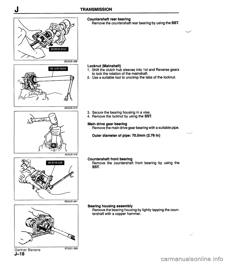
J TRANSMISSION Countershaft rear bearing Remove the countershaft rear bearing by using the SST. i/ Locknut (Mainshaft) 1. Shift the clutch hub sleeves into 1 st and Reverse gears to lock the rotation of the mainshaft. 2. Use a suitable tool to uncrimp the tabs of the locknut. 3. Secure the bearing housing in a vise. 4. Remove the locknut by using the SST. Main drive gear bearing Remove the main drive gear bearing with a suitable pipe. u Outer diameter of pipe: 70.0mm (2.76 in) Countershaft front bearing Remove the countershaft front bearing by using the SST. Bearing housing assembly Remove the bearing housing by lightly tapping the coun- tershaft with a copper hammer. Gartner Banana
Page 395 of 1708
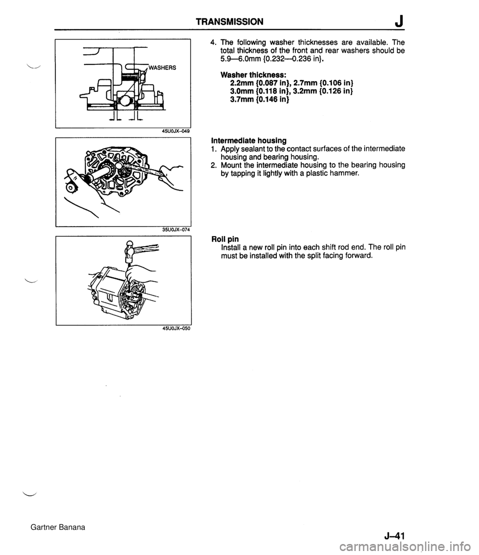
TRANSMISSION J 4. The following washer thicknesses are available. The total thickness of the front and rear washers should be 5.9--6.0mm I0.232--0.236 in). Washer thickness: 2.2mm (0.087 in), 2.7mm 10.106 in) 3.0mm (0.118 in), 3.2mm (0.126 in) 3.7mm (0.146 in) Intermediate housing 1. Apply sealant to the contact surfaces of the intermediate housing and bearing housing. 2. Mount the intermediate housing to the bearing housing by tapping it lightly with a plastic hammer. Roll pin Install a new roll pin into each shift rod end. The roll pin must be installed with the split facing forward. Gartner Banana
Page 397 of 1708
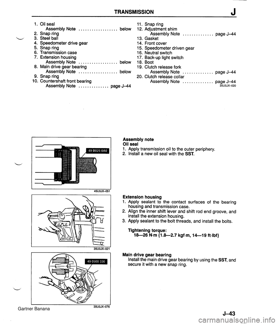
TRANSMISSION J 1. Oil seal Assembly Note .................. below 2. Snap ring u 3. Steel ball 4. Speedometer drive gear 5. Snap ring 6. Transmission case 7. Extension housing Assembly Note .................. below 8. Main drive gear bearing Assembly Note .................. below 9. Snap ring 10. Countershaft front bearing Assembly Note .............. page J-44 11. Snap ring 12. Adjustment shim Assembly Note .............. page J-44 13. Gasket 14. Front cover 15. Speedometer driven gear 16. Neutral switch 17. Back-up light switch 18. Boot 19. Clutch release fork Assembly Note .............. page J-44 20. Clutch release collar Assembly Note .............. page J-44 35UOJX-020 Assembly note Oil seal 1. Apply transmission oil to the outer periphery. 2. lnstall a new oil seal with the SST. Extension housing 1. Apply sealant to the contact surfaces of the bearing housing and transmission case. 2. Align the inner shift lever and shift rod end groove, and install the extension housing. 3. Apply sealant to the bolt threads, and install the bolts. Tightening torque: 18-26 N.m (1.8-2.7 kgf.m, l4--19 ft4bf) Main drive gear bearing Install the main drive gear bearing by using the SST, and secure it with a new snap ring. Gartner Banana
Page 409 of 1708
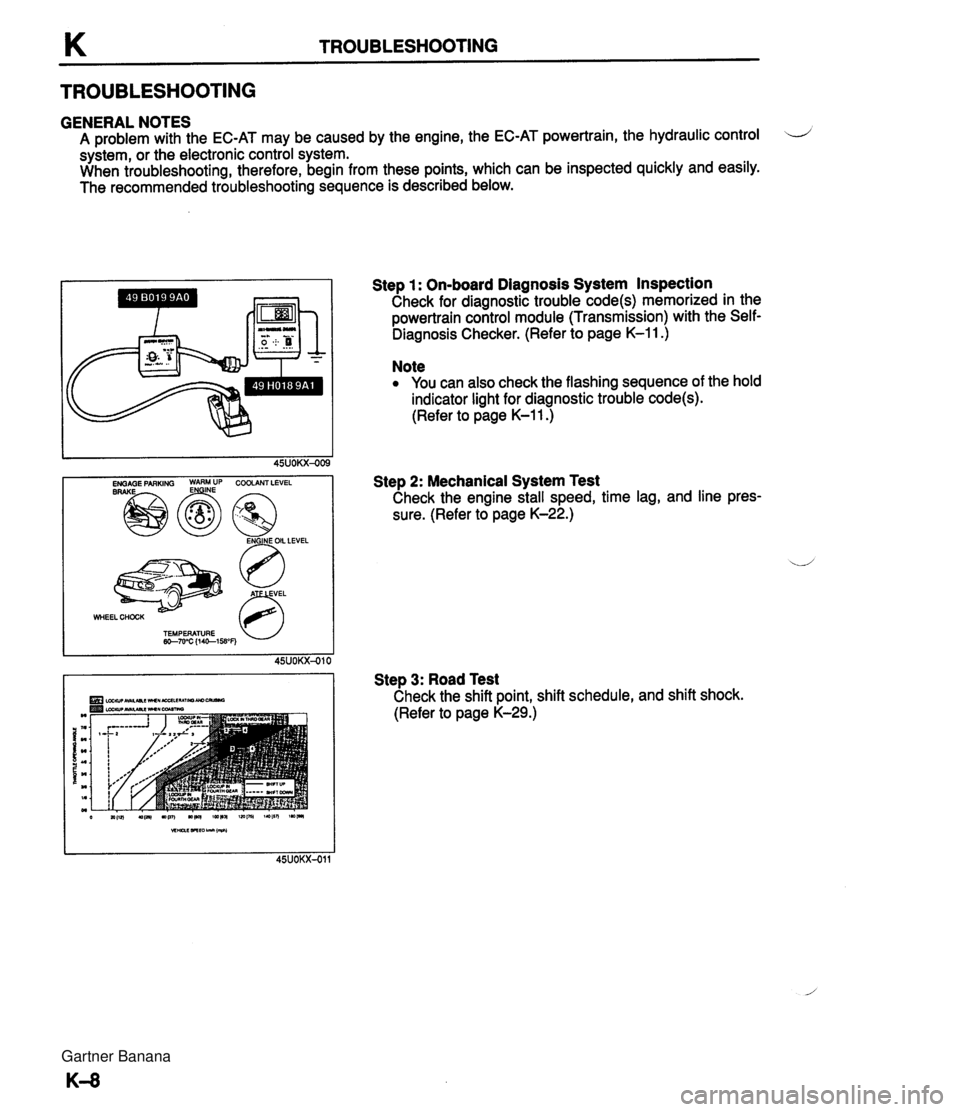
K TROUBLESHOOTING TROUBLESHOOTING GENERAL NOTES A problem with the EC-AT may be caused by the engine, the EC-AT powertrain, the hydraulic control LJ system, or the electronic control system. When troubleshooting, therefore, begin from these points, which can be inspected quickly and easily. The recommended troubleshooting sequence is described below. WHEEL CHOCK 63 TEMPERATURE w-7u'C (1461WF) Step 1 : On-board Diagnosis System Inspection Check for diagnostic trouble code(s) memorized in the powertrain control module (Transmission) with the Self- Diagnosis Checker. (Refer to page K-11 .) Note You can also check the flashing sequence of the hold indicator light for diagnostic trouble code(s). (Refer to page K-1 1 .) Step 2: Mechanical System Test Check the engine stall speed, time lag, and line pres- sure. (Refer to page K-22.) Step 3: Road Test Check the shift point, shift schedule, and shift shock. (Refer to page K-29.) Gartner Banana
Page 412 of 1708
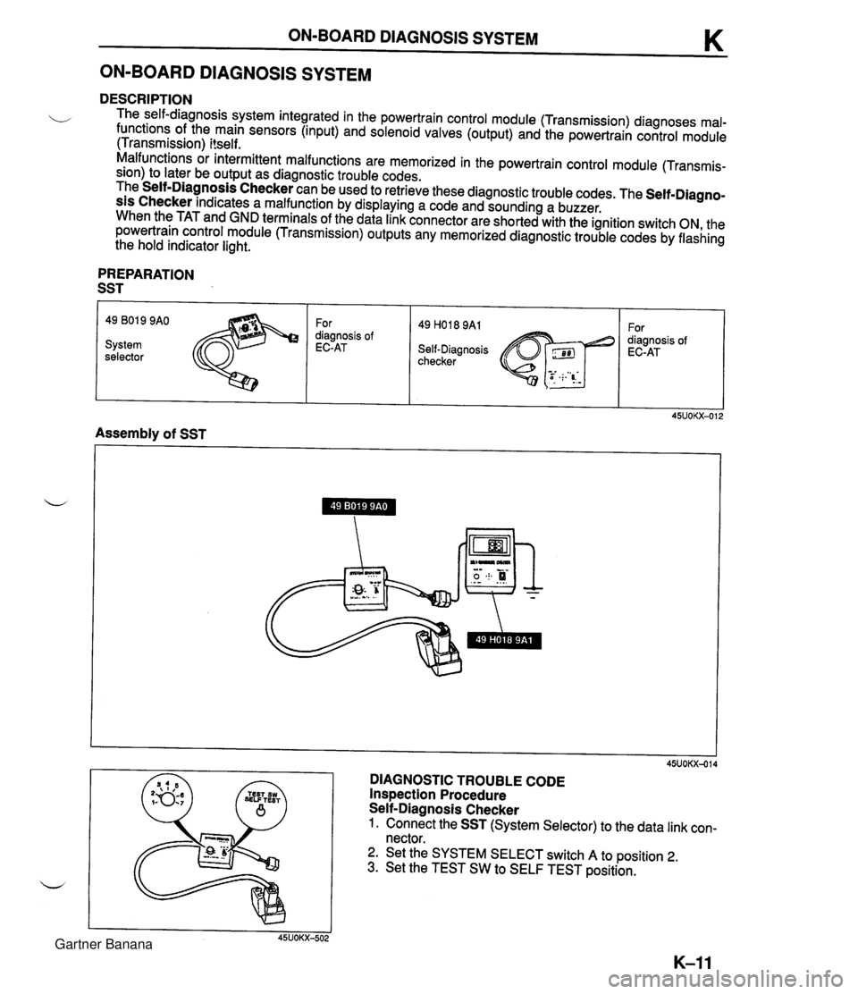
ON-BOARD DIAGNOSIS SYSTEM K ON-BOARD DIAGNOSIS SYSTEM DESCRIPTION The self-diagnosis system integrated in the powertrain control module (Transmission) diagnoses mal- functions of the main sensors (input) and solenoid valves (output) and the powertrain control module (Transmission) itself. Malfunctions or intermittent malfunctions are memorized in the powertrain control module (Transmis- sion) to later be output as diagnostic trouble codes. The Self-Diagnosis Checker can be used to retrieve these diagnostic trouble codes. The Self-Diagno- sis Checker indicates a malfunction by displaying a code and sounding a buzzer. When the TAT and GND terminals of the data link connector are shorted with the ignition switch ON, the powertrain control module (Transmission) outputs any memorized diagnostic trouble codes by flashing the hold indicator light. PREPARATION SST 49 801 9 9AO For 49 H018 9A1 For diagnosis of diagnosis of System EC-AT Self-Diagnosis EC-AT selector checker Assembly of SST DIAGNOSTIC TROUBLE CODE Inspection Procedure Self-Diagnosis Checker 1. Connect the SST (System Selector) to the data link con- nector. 2. Set the SYSTEM SELECT switch A to position 2. 3. Set the TEST SW to SELF TEST position. Gartner Banana
Page 413 of 1708
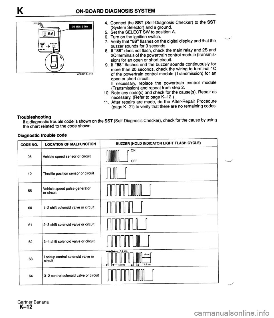
K ON-BOARD DIAGNOSIS SYSTEM Ill I 4. Connect the SST (Self-Diagnosis Checker) to the SST (System Selector) and a ground. 5. Set the SELECT SW to position A. 6. Turn on the ignition switch. ii 7. Verify that "88" flashes on the digital display and that the buzzer sounds for 3 seconds. 8. If "88" does not flash, check the main relay and 2s and 2Q terminals of the powertrain control module (transmis- sion) for an open or short circuit. 9. If "88" flashes and the buzzer sounds continuously for more than 20 seconds, check the wiring to terminal 1C of the powertrain control module (Transmission) for an open or short circuit. If necessary, replace the powertrain control module (Transmission) and repeat from step 2. 10. Note any code(s) and check for the cause(s). Repair as necessary. (Refer to page K-12.) 11. After repairs are made, do the After-Repair Procedure (page K-21) to verify that there are no remaining codes. Troubleshooting If a diagnostic trouble code is shown on the SST (Self-Diagnosis Checker), check for the cause by using the ch&t related to the code shown. Diagnostic trouble code ~U)DE NO. 1 LOCATION OF MALFUNCTION I BUZZER (HOLD INDICATOR LIGHT FLASH CYCLE) Throttle position sensor or circuit 06 Vehicle speed sensor or circuit 55 ON OFF Vehicle speed pulse generator or circuit 60 - 61 1-2 shift solenoid valve or circuit 62 - -- - 3-2 control solenoid valve or circuit 64 T 2-3 shift solenoid valve or circuit 63 - 3-4 shift solenoid valve or circuit -----a Lockup control solenoid valve or circuit -- --i---- - - - audrur - -, -. - 0.4 sec. - --I-& cl.2sec + 2 1.6sec * - 4 sec - - Gartner Banana
Page 414 of 1708
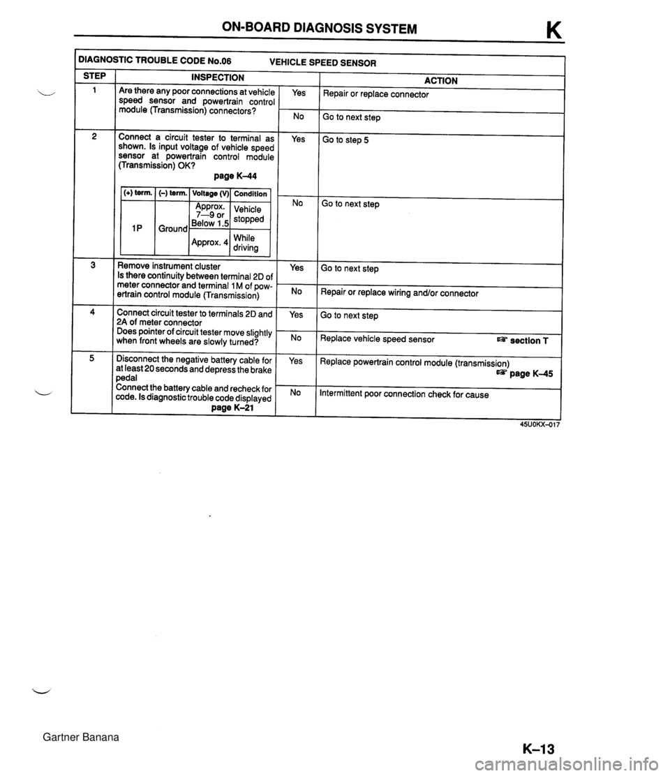
ON-BOARD DIAGNOSIS SYSTEM K )IAGNOSTIC TROUBLE CODE N0.06 VEHICLE SPEED SENSOR INSPECTION STEP ACTION Repair or replace connector Are there any poor connections at vehicle speed sensor and powertrain control module (Transmission) connectors? Yes Go to next step Connect a circuit tester to terminal as shown. Is input voltage of vehicle speed sensor at powertrain control module (Transmission) OK? page K-44 Yes Go to step 5 1 (+) term. I (-) term. ( Voltage (v)( Condition I Go to next step Below 1.5 While Remove instrument cluster Is there continuity between terminal 2D of meter connector and terminal 1 M of pow- ertrain control module (Transmission) Yes Go to next step Repair or replace wiring and/or connector Connect circuit tester to terminals 2D and 2A of meter connector Does pointer of circuit tester move slightly when front wheels are slowly turned? Yes Go to next step Replace vehicle speed sensor section T Disconnect the negative battery cable for at least 20 seconds and depress the brake pedal Connect the battery cable and recheck for code. Is diagnostic trouble code displayed Dane K-21 Yes Replace powertrain control module (transmission) page K-45 Intermittent poor connection check for cause Gartner Banana
Page 439 of 1708
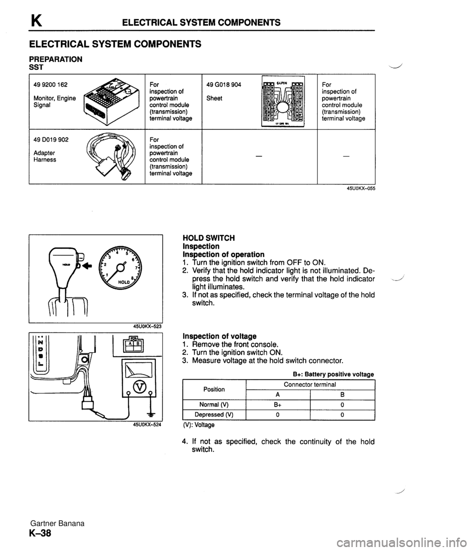
K ELECTRICAL SYSTEM COMPONENTS ELECTRICAL SYSTEM COMPONENTS PREPARATION SST 49 GO1 8 904 Sheet 49 9200 162 Monitor, Engine Signal - 49 DO1 9 902 Adapter Harness For inspection of powertrain control module (transmission) terminal voltage For inspection of powertrain control module (transmission) terminal voltage p@ HOLD For inspection of powertrain control module (transmission) terminal voltage HOLD SWITCH lnspection lnspection of operation 1. Turn the ignition switch from OFF to ON. 2. Verify that the hold indicator light is not illuminated. De- press the hold switch and verify that the hold indicator -J light illuminates. 3. If not as specified, check the terminal voltage of the hold switch. lnspection of voltage 1. Remove the front console. 2. Turn the ignition switch ON. 3. Measure voltage at the hold switch connector. B+: Battery positive voltage Position (V): Voltage Normal (V) Depressed (V) 4. If not as specified, check the continuity of the hold switch. Connector terminal A B+ 0 B 0 0 Gartner Banana