MAZDA MX-5 1997 Factory Repair Manual
Manufacturer: MAZDA, Model Year: 1997, Model line: MX-5, Model: MAZDA MX-5 1997Pages: 514, PDF Size: 17.89 MB
Page 291 of 514
Bushing Replacement
Cut or press old bushing from control arm. Coat new bushing with paraffin-based oil. Press new bushing into
control arm.
Installation (All Models)
To install, reverse removal procedure. Tighten upper control arm pivot bolts to specification with vehicle
resting on ground and suspension unloaded. See TORQUE SPECIFICATIONS
.
SHOCK ASSEMBLY
Removal (1997)
Raise and support vehicle. Remove wheel assembly. Remove engine splash shield. Remove wheel speed sensor
harness band. Remove stabilizer link bolt. Remove upper control arm ball joint cotter pin and nut. Separate
upper control arm ball joint stud from knuckle using Puller (49-0118-850C). Loosen lower control arm pivot
bolts. Remove shock upper mount nuts and lower bolt. Move lower control arm just enough to remove shock
assembly. DO NOT damage brake line.
Removal (1999 & 2000)
Raise and support vehicle. Remove wheel assembly. Remove engine splash shield. Remove wheel speed sensor.
Remove stabilizer link bolt. Separate lower control arm ball joint stud from knuckle using Puller (49-T028-
3A0). Loosen lower control arm pivot bolts. Inside engine compartment, on 1999 models, remove strut bar. See
FRONT STRUT BAR (1999)
. On 2000 models, remove shock upper mount nuts. On all models, under car,
remove lower bolt. Move lower control arm just enough to remove shock assembly. DO NOT damage brake
line.
Disassembly
Clamp upper shock mount in vise. Loosen piston lock nut 2 turns only. Compress coil spring using coil spring
compressor. Remove piston lock nut. Slowly release compressor tension. Remove components. Remove coil
spring. Remove shock from vise.
Inspection
Check shock tube for damage, oil leakage and abnormal noise. Check rubber components for deterioration or
damage. Inspect coil spring for signs of fatigue or damage. Replace components as necessary.
Reassembly (1997)
Clamp shock in vise. Install coil spring and components in reverse order of disassembly. Ensure coil spring is
well seated in upper and lower spring seats. See Fig. 2
. Tighten piston rod nut. See TORQUE
SPECIFICATIONS .
1997 Mazda MX-5 Miata
1997-2000 SUSPENSION Front - Miata
Microsoft
Sunday, July 05, 2009 1:38:08 PMPage 4 © 2005 Mitchell Repair Information Company, LLC.
Page 292 of 514
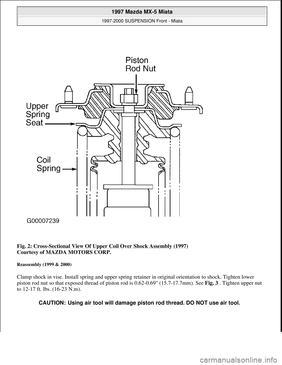
Fig. 2: Cross-Sectional View Of Upper Coil Over Shock Assembly (1997)
Courtesy of MAZDA MOTORS CORP.
Reassembly (1999 & 2000)
Clamp shock in vise. Install spring and upper spring retainer in original orientation to shock. Tighten lower
piston rod nut so that exposed thread of piston rod is 0.62-0.69" (15.7-17.7mm). See Fig. 3 . Tighten upper nut
to 12-17 ft. lbs. (16-23 N.m).
CAUTION: Using air tool will damage piston rod thread. DO NOT use air tool.
1997 Mazda MX-5 Miata
1997-2000 SUSPENSION Front - Miata
Microsoft
Sunday, July 05, 2009 1:38:08 PMPage 5 © 2005 Mitchell Repair Information Company, LLC.
Page 293 of 514
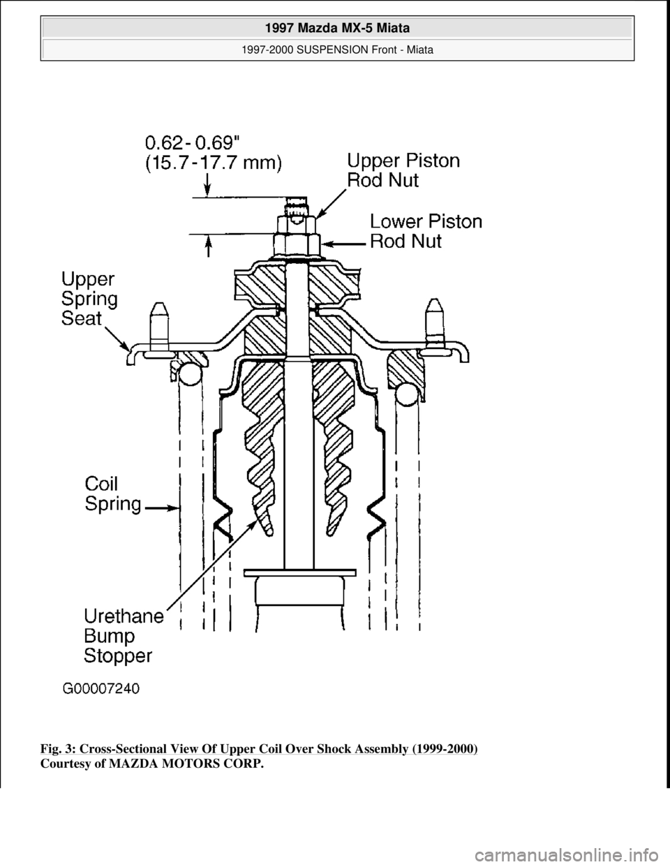
Fig. 3: Cross-Sectional View Of Upper Coil Over Shock Assembly (1999-2000)
Courtesy of MAZDA MOTORS CORP.
1997 Mazda MX-5 Miata
1997-2000 SUSPENSION Front - Miata
Microsoft
Sunday, July 05, 2009 1:38:08 PMPage 6 © 2005 Mitchell Repair Information Company, LLC.
Page 294 of 514
Installation
To install, reverse removal procedure. Fully tighten all bolts with vehicle resting on ground and suspension
unloaded. See TORQUE SPECIFICATIONS
. Check front wheel alignment. See SPECIFICATIONS &
PROCEDURES article in WHEEL ALIGNMENT.
STABILIZER BAR
Removal & Installation
Raise and support vehicle. Remove engine splash shield. Remove frame brackets and bushings. Remove
stabilizer control links. Align bushing with installation mark on stabilizer. Reverse removable procedure for
installation. See TORQUE SPECIFICATIONS
.
FRONT STRUT BAR (1999)
Removal & Installation
1. To remove strut bar located in engine compartment mounted on top of shock towers, loosen lock nuts on
joint bolt and loosen joint bolt. Remove nut, washer and bolt retaining strut bar to strut plate. Remove
strut bar from vehicle.
2. To install, reverse removal procedure. Rotate joint bolt counterclockwise to 3.5-5.2 INCH lbs. (.4-.6 N.m)
to set tension. Tighten lock nuts to 87-121 INCH lbs. (10-14 N.m). Tighten strut bar-to-strut plate nut.
See TORQUE SPECIFICATIONS
.
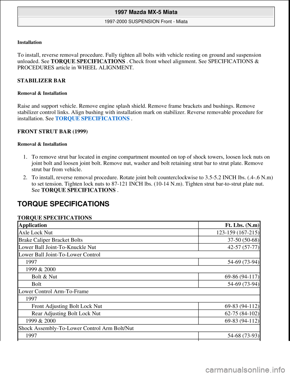
TORQUE SPECIFICATIONS
TORQUE SPECIFICATIONS
ApplicationFt. Lbs. (N.m)
Axle Lock Nut123-159 (167-215)
Brake Caliper Bracket Bolts37-50 (50-68)
Lower Ball Joint-To-Knuckle Nut42-57 (57-77)
Lower Ball Joint-To-Lower Control
199754-69 (73-94)
1999 & 2000
Bolt & Nut69-86 (94-117)
Bolt54-69 (73-94)
Lower Control Arm-To-Frame
1997
Front Adjusting Bolt Lock Nut69-83 (94-112)
Rear Adjusting Bolt Lock Nut62-75 (84-102)
1999 & 200069-83 (94-112)
Shock Assembly-To-Lower Control Arm Bolt/Nut
199754-68 (73-93)
1997 Mazda MX-5 Miata
1997-2000 SUSPENSION Front - Miata
Microsoft
Sunday, July 05, 2009 1:38:08 PMPage 7 © 2005 Mitchell Repair Information Company, LLC.
Page 295 of 514
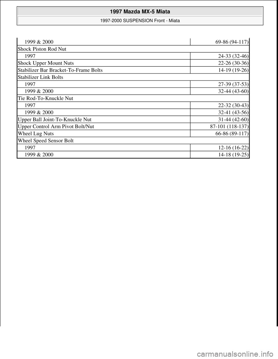
1999 & 200069-86 (94-117)
Shock Piston Rod Nut
199724-33 (32-46)
Shock Upper Mount Nuts22-26 (30-36)
Stabilizer Bar Bracket-To-Frame Bolts14-19 (19-26)
Stabilizer Link Bolts
199727-39 (37-53)
1999 & 200032-44 (43-60)
Tie Rod-To-Knuckle Nut
199722-32 (30-43)
1999 & 200032-41 (43-56)
Upper Ball Joint-To-Knuckle Nut31-44 (42-60)
Upper Control Arm Pivot Bolt/Nut87-101 (118-137)
Wheel Lug Nuts66-86 (89-117)
Wheel Speed Sensor Bolt
199712-16 (16-22)
1999 & 200014-18 (19-25)
1997 Mazda MX-5 Miata
1997-2000 SUSPENSION Front - Miata
Microsoft
Sunday, July 05, 2009 1:38:08 PMPage 8 © 2005 Mitchell Repair Information Company, LLC.
Page 296 of 514
1997 ELECTRICAL
Fuses & Circuit Breakers - MX-5 Miata
IDENTIFICATION
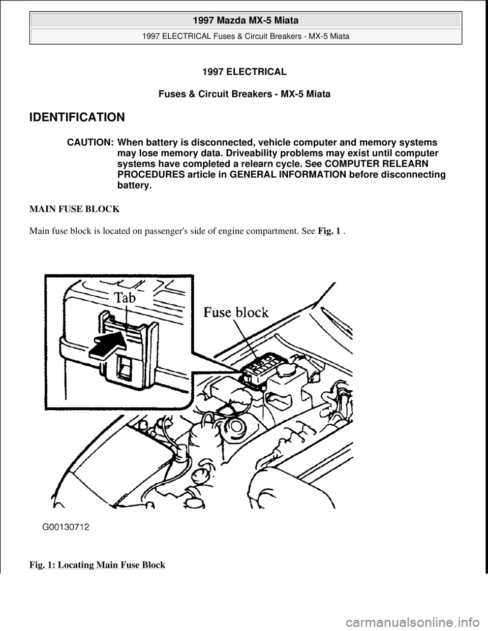
MAIN FUSE BLOCK
Main fuse block is located on passenger's side of engine compartment. See Fig. 1
.
Fig. 1: Locating Main Fuse Block
CAUTION: When battery is disconnected, vehicle computer and memory systems
may lose memory data. Driveability problems may exist until computer
systems have completed a relearn cycle. See COMPUTER RELEARN
PROCEDURES article in GENERAL INFORMATION before disconnecting
battery.
1997 Mazda MX-5 Miata
1997 ELECTRICAL Fuses & Circuit Breakers - MX-5 Miata
1997 Mazda MX-5 Miata
1997 ELECTRICAL Fuses & Circuit Breakers - MX-5 Miata
Microsoft
Sunday, July 05, 2009 1:54:39 PMPage 1 © 2005 Mitchell Repair Information Company, LLC.
Microsoft
Sunday, July 05, 2009 1:54:43 PMPage 1 © 2005 Mitchell Repair Information Company, LLC.
Page 297 of 514
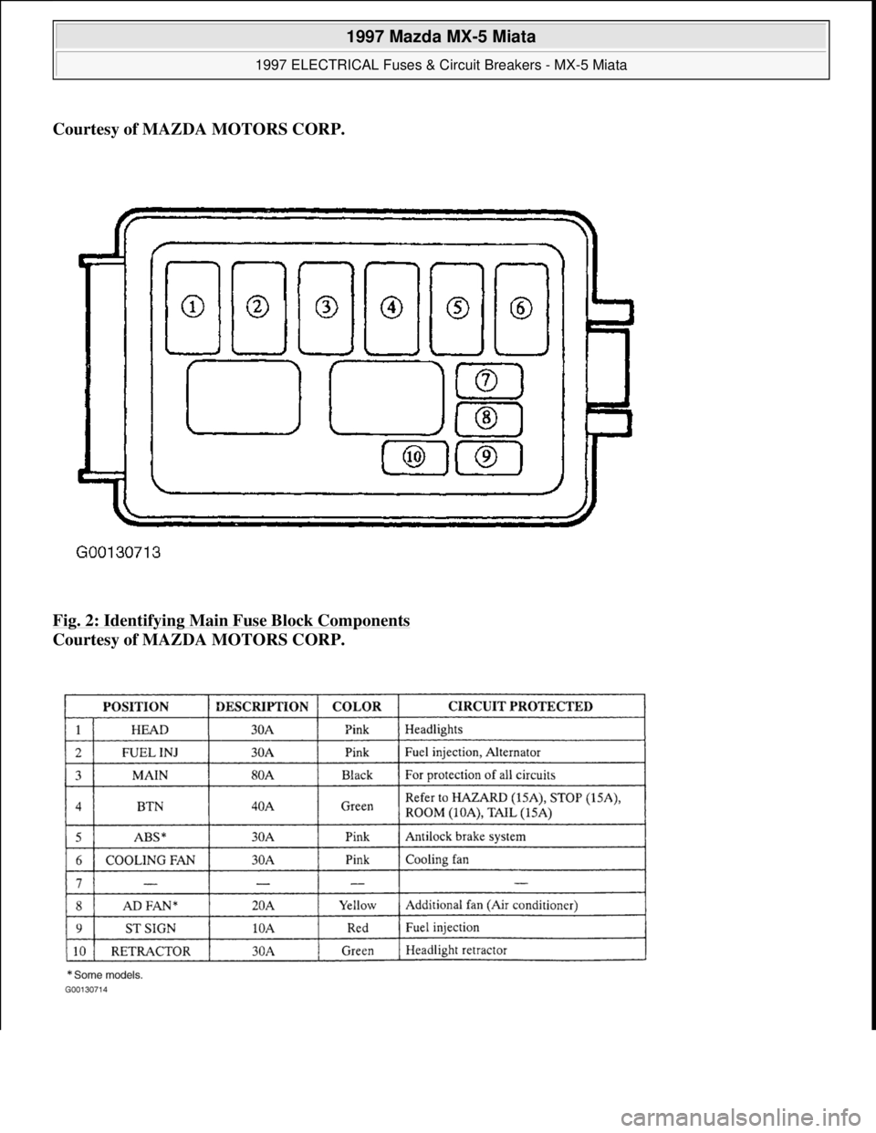
Courtesy of MAZDA MOTORS CORP.
Fig. 2: Identifying Main Fuse Block Components
Courtesy of MAZDA MOTORS CORP.
1997 Mazda MX-5 Miata
1997 ELECTRICAL Fuses & Circuit Breakers - MX-5 Miata
Microsoft
Sunday, July 05, 2009 1:54:39 PMPage 2 © 2005 Mitchell Repair Information Company, LLC.
Page 298 of 514
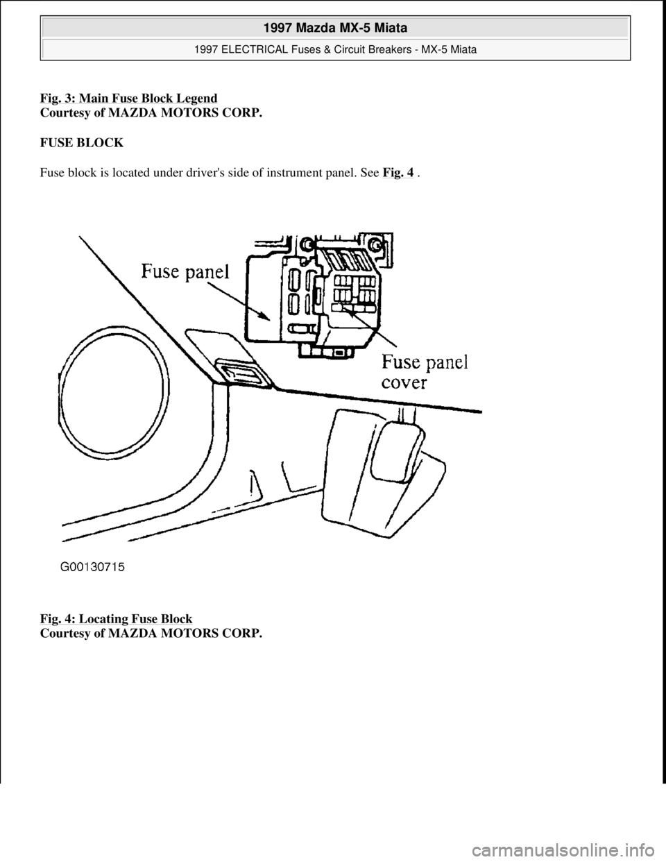
Fig. 3: Main Fuse Block Legend
Courtesy of MAZDA MOTORS CORP.
FUSE BLOCK
Fuse block is located under driver's side of instrument panel. See Fig. 4
.
Fig. 4: Locating Fuse Block
Courtesy of MAZDA MOTORS CORP.
1997 Mazda MX-5 Miata
1997 ELECTRICAL Fuses & Circuit Breakers - MX-5 Miata
Microsoft
Sunday, July 05, 2009 1:54:39 PMPage 3 © 2005 Mitchell Repair Information Company, LLC.
Page 299 of 514
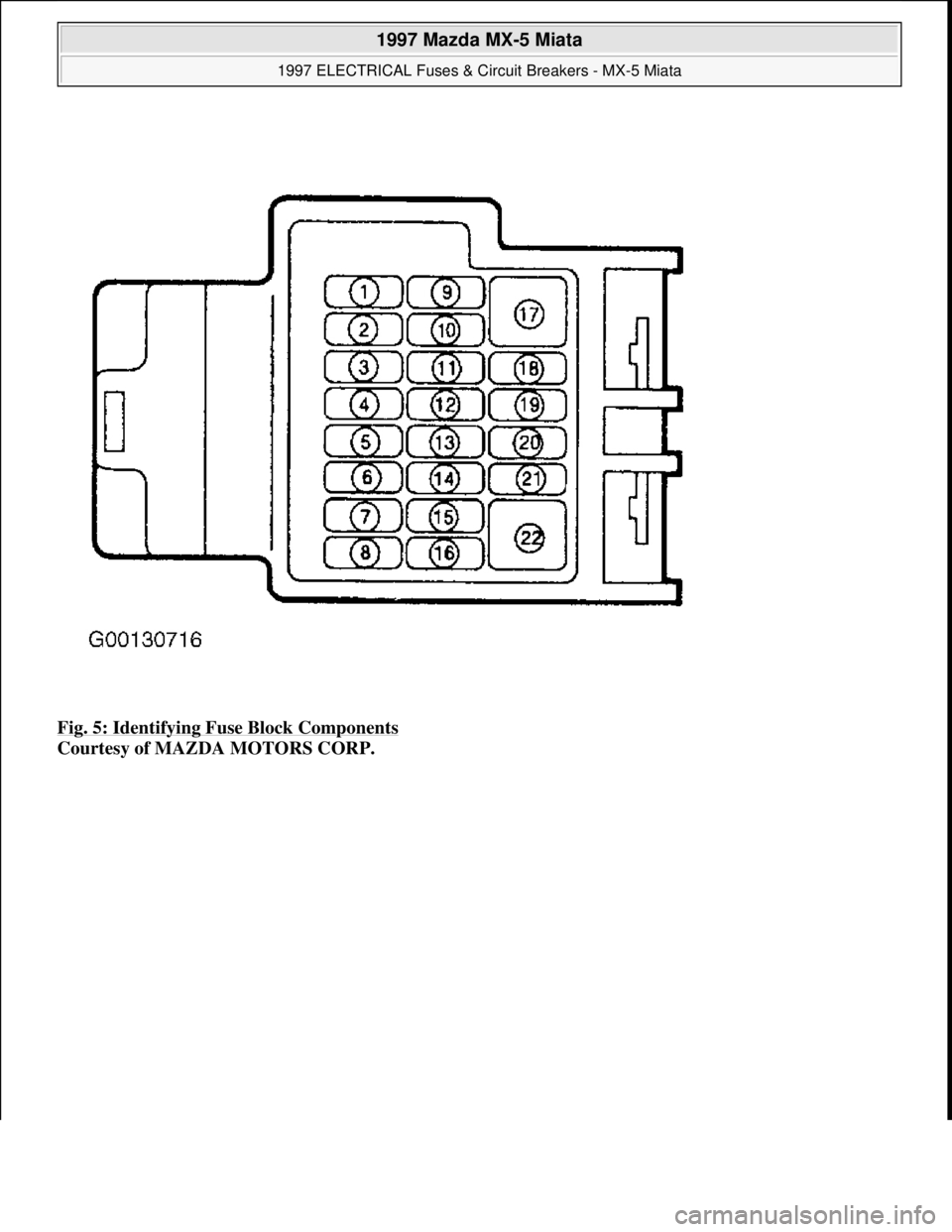
Fig. 5: Identifying Fuse Block Components
Courtesy of MAZDA MOTORS CORP.
1997 Mazda MX-5 Miata
1997 ELECTRICAL Fuses & Circuit Breakers - MX-5 Miata
Microsoft
Sunday, July 05, 2009 1:54:39 PMPage 4 © 2005 Mitchell Repair Information Company, LLC.
Page 300 of 514
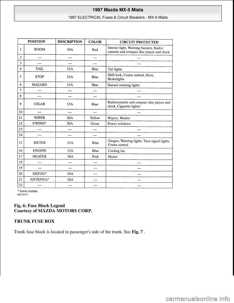
Fig. 6: Fuse Block Legend
Courtesy of MAZDA MOTORS CORP.
TRUNK FUSE BOX
Trunk fuse block is located in passen
ger's side of the trunk. See Fig. 7.
1997 Mazda MX-5 Miata
1997 ELECTRICAL Fuses & Circuit Breakers - MX-5 Miata
Microsoft
Sunday, July 05, 2009 1:54:39 PMPage 5 © 2005 Mitchell Repair Information Company, LLC.