MAZDA MX-5 1997 Factory Repair Manual
Manufacturer: MAZDA, Model Year: 1997, Model line: MX-5, Model: MAZDA MX-5 1997Pages: 514, PDF Size: 17.89 MB
Page 371 of 514
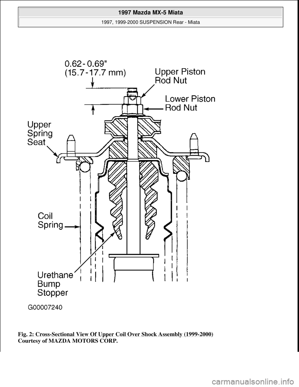
Fig. 2: Cross-Sectional View Of Upper Coil Over Shock Assembly (1999-2000)
Courtesy of MAZDA MOTORS CORP.
1997 Mazda MX-5 Miata
1997, 1999-2000 SUSPENSION Rear - Miata
Microsoft
Sunday, July 05, 2009 1:38:49 PMPage 4 © 2005 Mitchell Repair Information Company, LLC.
Page 372 of 514
Installation
Reinstall shock in reverse order. Tighten nuts and bolts to specification with vehicle resting on ground and
suspension unloaded. See TORQUE SPECIFICATIONS
. Check rear wheel alignment. See
SPECIFICATIONS & PROCEDURES article in WHEEL ALIGNMENT.
LOWER ARM
Removal
Raise and support vehicle. Remove rear wheel assembly. Remove stabilizer bar control link nut and bolt. See
Fig. 3
. Remove lower shock bolt. Remove lower arm-to-crossmember bolts. Remove lower arm-to-knuckle
bolts. Remove lower arm. Inspect arm for damage, cracks and deformation. Check for damaged or worn
bushings.
Installation
To install, reverse removal procedure. Tighten all nuts/bolts to specification with vehicle resting on ground and
suspension unloaded. See TORQUE SPECIFICATIONS
. Adjust rear wheel alignment. See
SPECIFICATIONS & PROCEDURES article in WHEEL ALIGNMENT.
1997 Mazda MX-5 Miata
1997, 1999-2000 SUSPENSION Rear - Miata
Microsoft
Sunday, July 05, 2009 1:38:49 PMPage 5 © 2005 Mitchell Repair Information Company, LLC.
Page 373 of 514
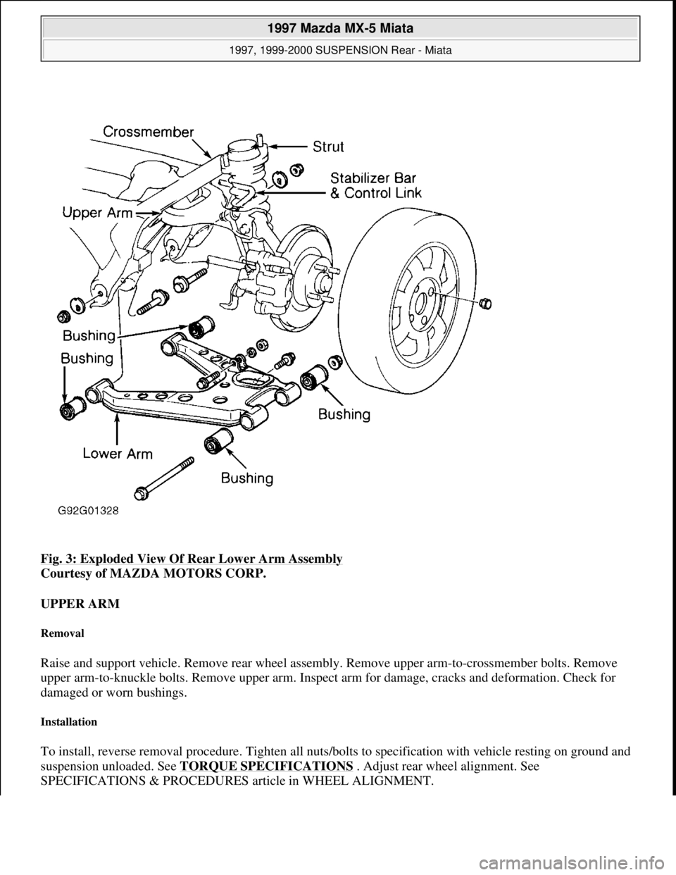
Fig. 3: Exploded View Of Rear Lower Arm Assembly
Courtesy of MAZDA MOTORS CORP.
UPPER ARM
Removal
Raise and support vehicle. Remove rear wheel assembly. Remove upper arm-to-crossmember bolts. Remove
upper arm-to-knuckle bolts. Remove upper arm. Inspect arm for damage, cracks and deformation. Check for
damaged or worn bushings.
Installation
To install, reverse removal procedure. Tighten all nuts/bolts to specification with vehicle resting on ground and
suspension unloaded. See TORQUE SPECIFICATIONS
. Adjust rear wheel alignment. See
SPECIFICATIONS & PROCEDURES article in WHEEL ALIGNMENT.
1997 Mazda MX-5 Miata
1997, 1999-2000 SUSPENSION Rear - Miata
Microsoft
Sunday, July 05, 2009 1:38:49 PMPage 6 © 2005 Mitchell Repair Information Company, LLC.
Page 374 of 514
STABILIZER BAR
Removal
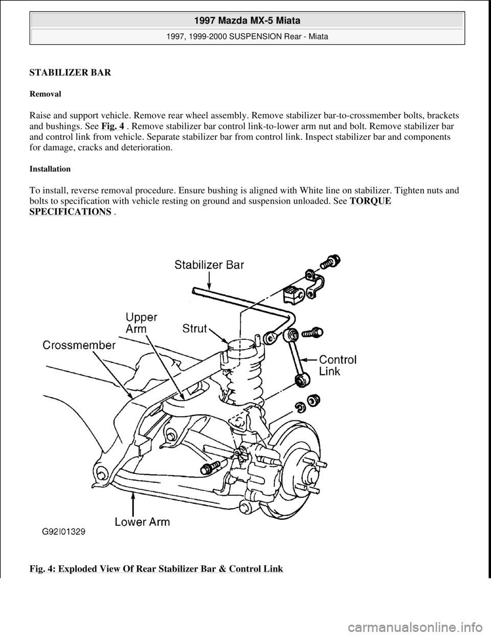
Raise and support vehicle. Remove rear wheel assembly. Remove stabilizer bar-to-crossmember bolts, brackets
and bushings. See Fig. 4
. Remove stabilizer bar control link-to-lower arm nut and bolt. Remove stabilizer bar
and control link from vehicle. Separate stabilizer bar from control link. Inspect stabilizer bar and components
for damage, cracks and deterioration.
Installation
To install, reverse removal procedure. Ensure bushing is aligned with White line on stabilizer. Tighten nuts and
bolts to specification with vehicle resting on ground and suspension unloaded. See TORQUE
SPECIFICATIONS .
Fig. 4: Exploded View Of Rear Stabilizer Bar & Control Link
1997 Mazda MX-5 Miata
1997, 1999-2000 SUSPENSION Rear - Miata
Microsoft
Sunday, July 05, 2009 1:38:49 PMPage 7 © 2005 Mitchell Repair Information Company, LLC.
Page 375 of 514
Courtesy of MAZDA MOTORS CORP.
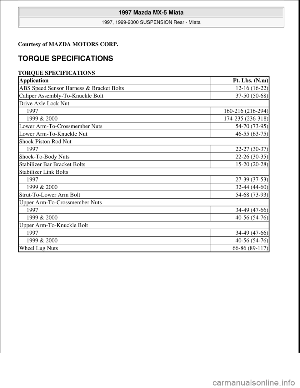
TORQUE SPECIFICATIONS
TORQUE SPECIFICATIONS
ApplicationFt. Lbs. (N.m)
ABS Speed Sensor Harness & Bracket Bolts12-16 (16-22)
Caliper Assembly-To-Knuckle Bolt37-50 (50-68)
Drive Axle Lock Nut
1997160-216 (216-294)
1999 & 2000174-235 (236-318)
Lower Arm-To-Crossmember Nuts54-70 (73-95)
Lower Arm-To-Knuckle Nut46-55 (63-75)
Shock Piston Rod Nut
199722-27 (30-37)
Shock-To-Body Nuts22-26 (30-35)
Stabilizer Bar Bracket Bolts15-20 (20-28)
Stabilizer Link Bolts
199727-39 (37-53)
1999 & 200032-44 (44-60)
Strut-To-Lower Arm Bolt54-68 (73-93)
Upper Arm-To-Crossmember Nuts
199734-49 (47-66)
1999 & 200040-56 (54-76)
Upper Arm-To-Knuckle Bolt
199734-49 (47-66)
1999 & 200040-56 (54-76)
Wheel Lug Nuts66-86 (89-117)
1997 Mazda MX-5 Miata
1997, 1999-2000 SUSPENSION Rear - Miata
Microsoft
Sunday, July 05, 2009 1:38:49 PMPage 8 © 2005 Mitchell Repair Information Company, LLC.
Page 376 of 514
STARTER - DIRECT DRIVE
1997 STARTING & CHARGING SYSTEMS Mazda - Starters - Direct Drive
DESCRIPTION & OPERATION
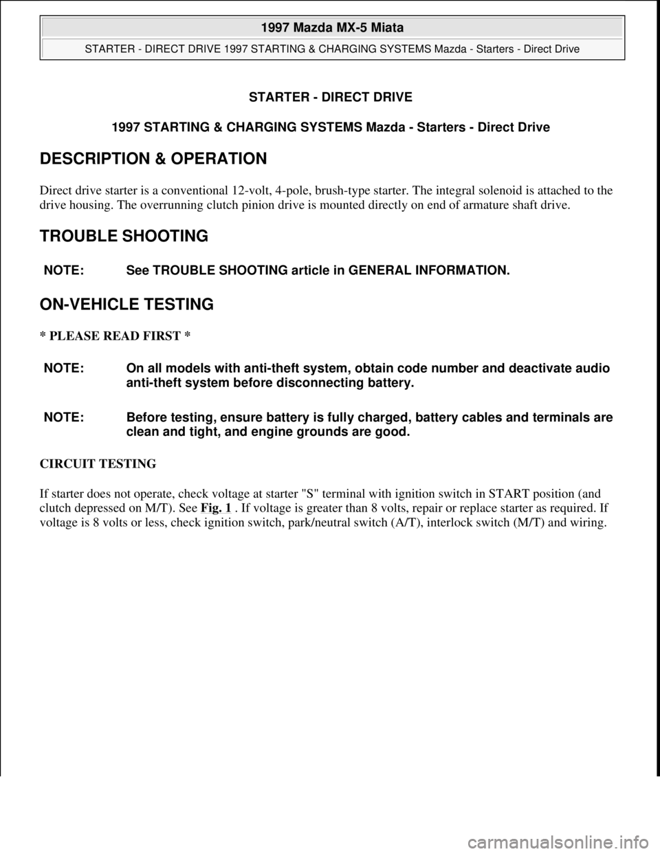
Direct drive starter is a conventional 12-volt, 4-pole, brush-type starter. The integral solenoid is attached to the
drive housing. The overrunning clutch pinion drive is mounted directly on end of armature shaft drive.
TROUBLE SHOOTING
ON-VEHICLE TESTING
* PLEASE READ FIRST *
CIRCUIT TESTING
If starter does not operate, check voltage at starter "S" terminal with ignition switch in START position (and
clutch depressed on M/T). See Fig. 1
. If voltage is greater than 8 volts, repair or replace starter as required. If
volta
ge is 8 volts or less, check ignition switch, park/neutral switch (A/T), interlock switch (M/T) and wiring. NOTE: See TROUBLE SHOOTING article in GENERAL INFORMATION.
NOTE: On all models with anti-theft system, obtain code number and deactivate audio
anti-theft system before disconnecting battery.
NOTE: Before testing, ensure battery is fully charged, battery cables and terminals are
clean and tight, and engine grounds are good.
1997 Mazda MX-5 Miata
STARTER - DIRECT DRIVE 1997 STARTING & CHARGING SYSTEMS Mazda - Starters - Direct Drive
1997 Mazda MX-5 Miata
STARTER - DIRECT DRIVE 1997 STARTING & CHARGING SYSTEMS Mazda - Starters - Direct Drive
Microsoft
Sunday, July 05, 2009 1:56:15 PMPage 1 © 2005 Mitchell Repair Information Company, LLC.
Microsoft
Sunday, July 05, 2009 1:56:20 PMPage 1 © 2005 Mitchell Repair Information Company, LLC.
Page 377 of 514
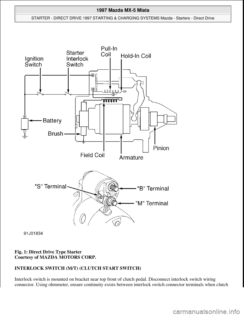
Fig. 1: Direct Drive Type Starter
Courtesy of MAZDA MOTORS CORP.
INTERLOCK SWITCH (M/T) (CLUTCH START SWITCH)
Interlock switch is mounted on bracket near top front of clutch pedal. Disconnect interlock switch wiring
connector. Using ohmmeter, ensure continuity exists between interlock switch connector terminals when clutch
1997 Mazda MX-5 Miata
STARTER - DIRECT DRIVE 1997 STARTING & CHARGING SYSTEMS Mazda - Starters - Direct Drive
Microsoft
Sunday, July 05, 2009 1:56:15 PMPage 2 © 2005 Mitchell Repair Information Company, LLC.
Page 378 of 514
pedal is depressed. If continuity does not exist, adjust or replace interlock switch.
BENCH TESTING
NO-LOAD TEST
Connect fully-charged 12-volt battery, voltmeter and ammeter to starter. See Fig. 2
. Using remote starter wires
or jumper, engage solenoid. Starter should spin smoothly. Compare readings with specifications. See NO
-
LOAD TEST SPECIFICATIONS table. If voltage is less than specified, amperage is more than specified or
shaft speed is less than specified, disassemble and inspect starter components.
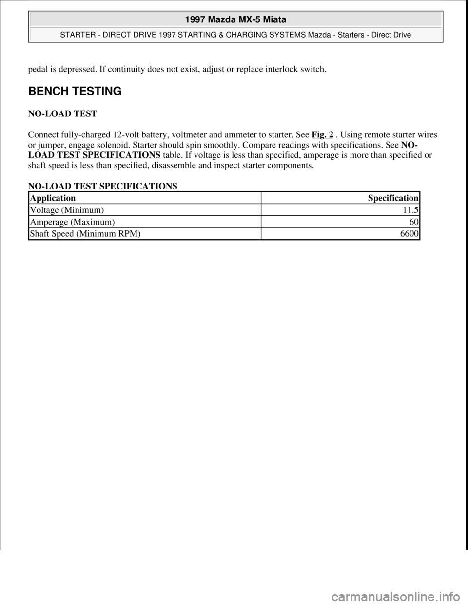
NO-LOAD TEST SPECIFICATIONS
ApplicationSpecification
Voltage (Minimum)11.5
Amperage (Maximum)60
Shaft Speed (Minimum RPM)6600
1997 Mazda MX-5 Miata
STARTER - DIRECT DRIVE 1997 STARTING & CHARGING SYSTEMS Mazda - Starters - Direct Drive
Microsoft
Sunday, July 05, 2009 1:56:15 PMPage 3 © 2005 Mitchell Repair Information Company, LLC.
Page 379 of 514
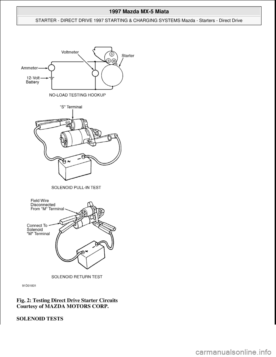
Fig. 2: Testing Direct Drive Starter Circuits
Courtesy of MAZDA MOTORS CORP.
SOLENOID TESTS
1997 Mazda MX-5 Miata
STARTER - DIRECT DRIVE 1997 STARTING & CHARGING SYSTEMS Mazda - Starters - Direct Drive
Microsoft
Sunday, July 05, 2009 1:56:15 PMPage 4 © 2005 Mitchell Repair Information Company, LLC.
Page 380 of 514
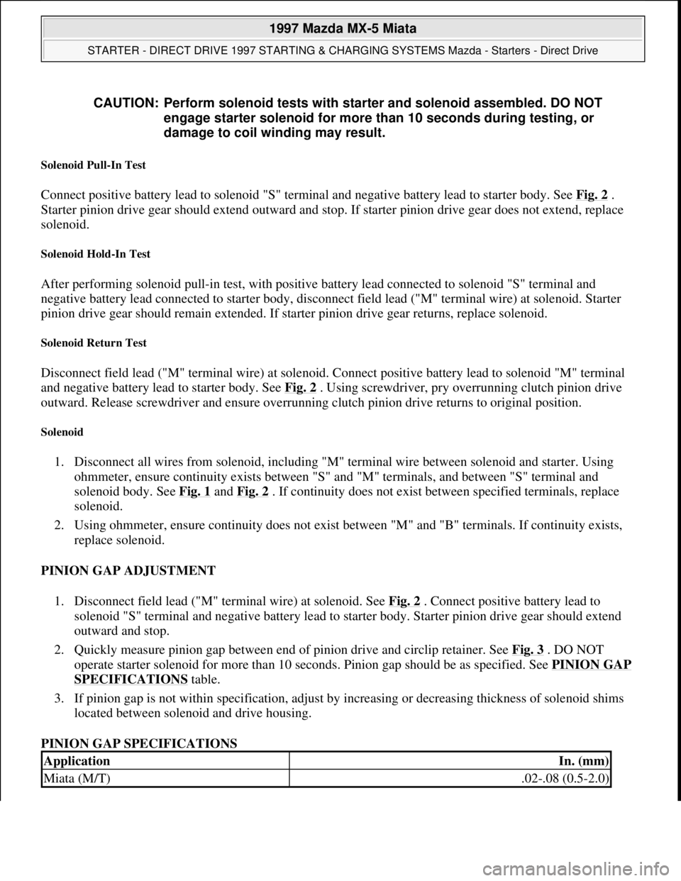
Solenoid Pull-In Test
Connect positive battery lead to solenoid "S" terminal and negative battery lead to starter body. See Fig. 2 .
Starter pinion drive gear should extend outward and stop. If starter pinion drive gear does not extend, replace
solenoid.
Solenoid Hold-In Test
After performing solenoid pull-in test, with positive battery lead connected to solenoid "S" terminal and
negative battery lead connected to starter body, disconnect field lead ("M" terminal wire) at solenoid. Starter
pinion drive gear should remain extended. If starter pinion drive gear returns, replace solenoid.
Solenoid Return Test
Disconnect field lead ("M" terminal wire) at solenoid. Connect positive battery lead to solenoid "M" terminal
and negative battery lead to starter body. See Fig. 2
. Using screwdriver, pry overrunning clutch pinion drive
outward. Release screwdriver and ensure overrunning clutch pinion drive returns to original position.
Solenoid
1. Disconnect all wires from solenoid, including "M" terminal wire between solenoid and starter. Using
ohmmeter, ensure continuity exists between "S" and "M" terminals, and between "S" terminal and
solenoid body. See Fig. 1
and Fig. 2 . If continuity does not exist between specified terminals, replace
solenoid.
2. Using ohmmeter, ensure continuity does not exist between "M" and "B" terminals. If continuity exists,
replace solenoid.
PINION GAP ADJUSTMENT
1. Disconnect field lead ("M" terminal wire) at solenoid. See Fig. 2
. Connect positive battery lead to
solenoid "S" terminal and negative battery lead to starter body. Starter pinion drive gear should extend
outward and stop.
2. Quickly measure pinion gap between end of pinion drive and circlip retainer. See Fig. 3
. DO NOT
operate starter solenoid for more than 10 seconds. Pinion gap should be as specified. See PINION GAP
SPECIFICATIONS table.
3. If pinion gap is not within specification, adjust by increasing or decreasing thickness of solenoid shims
located between solenoid and drive housing.
PINION GAP SPECIFICATIONS CAUTION: Perform solenoid tests with starter and solenoid assembled. DO NOT
engage starter solenoid for more than 10 seconds during testing, or
damage to coil winding may result.
ApplicationIn. (mm)
Miata (M/T).02-.08 (0.5-2.0)
1997 Mazda MX-5 Miata
STARTER - DIRECT DRIVE 1997 STARTING & CHARGING SYSTEMS Mazda - Starters - Direct Drive
Microsoft
Sunday, July 05, 2009 1:56:16 PMPage 5 © 2005 Mitchell Repair Information Company, LLC.