boot MAZDA PROTEGE 1992 Workshop Manual
[x] Cancel search | Manufacturer: MAZDA, Model Year: 1992, Model line: PROTEGE, Model: MAZDA PROTEGE 1992Pages: 1164, PDF Size: 81.9 MB
Page 22 of 1164
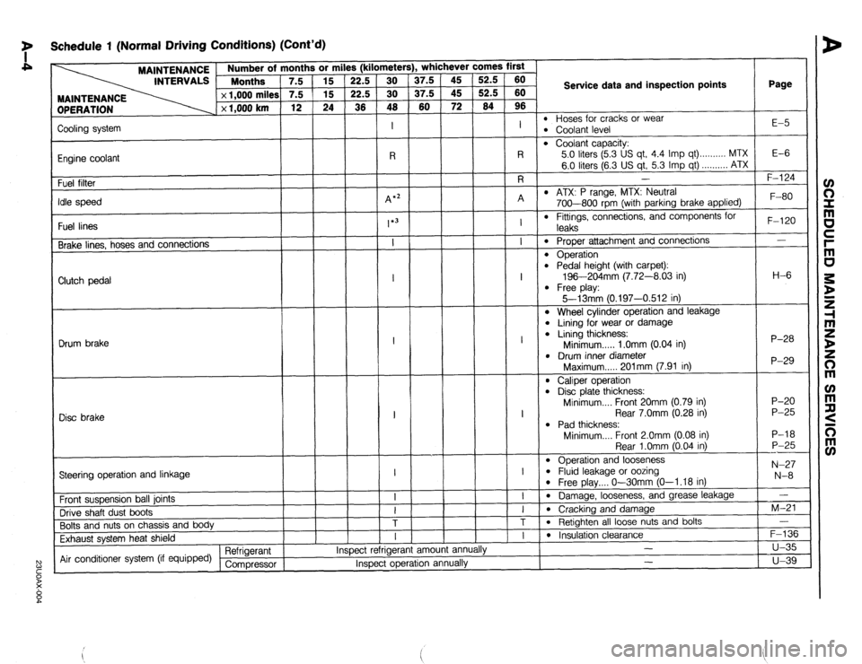
7 Schedule 1 (Normal Driving Conditions) (Cont’d)
MAINTENANCE
INTERVALS 1 ::::“’ rths ’ 7.5
DPERATION x 1,000 miles
x 1,000 km 3r mi
15
15
24
1
Page
l- . whichever comes first s (kilometer!
37.5
37.5
60 52.5
52.5
64 60
60
96
I
l-7
Service data and inspection points
l Hoses for cracks or wear l Coolant level E-5
Zooling system
Engine coolant
Fuel filter
‘die speed
Fuel lines
Brake lines, hoses and connections
l Coolant capacity:
5.0 liters (5.3 US qt, 4.4 Imp qt) . . . . . . . . . . MTX
6.0 liters (6.3 US qt, 5.3 Imp qt) . . . . . . . . . . ATX
I E-6 -
F-l 24
l ATX: P range, MTX: Neutral
700-800 rpm (with parking brake applied)
l Fittings, connections, and components for F-80
F-120
-
H-6
P-28
P-29
P-20
P-25
P-18
P-25
---
N-27
N-8
-
M-21
-
F-136
u-35
u-39 leaks
0 Proper attachment and connections
l Operation l Pedal height (with carpet):
196-204mm (7.72-8.03 in)
l Free play:
5--13mm 10.197-0.512 in) Clutch pedal
l Wheel cylinder operation and leakage
l Lining for wear or damage l Lining thickness:
Minimum . . . . . 1 .Omm (0.04 in)
l Drum inner diameter
Maximum..... 201mm (7.91 in) Drum brake
l Caliper operation l Disc plate thickness:
Minimum.... Front 20mm (0.79 in)
Rear 7.0mm (0.28 in)
l Pad thickness:
Minimum.... Front 2.0mm (0.08 in)
Rear l.Omm (0.04 in)
l Operation and looseness l Fluid leakage or oozing l Free play.... O-30mm (O-l .18 in)
l Damage, looseness, and grease leakage
l Cracking and damage
l Retighten all loose nuts and bolts I
1
Disc brake
I
---l-T
Steering operation and linkage
Front suspension ball joints
Drive shaft dust boots
Bolts and nuts on chassis and body
Exhaust system heat shield
Air conditioner system (if equipped) Refrigerant
Compressor am01 anni I
l Insulation clearance
- ,.
Inspect rerrlgerar
Inspect operation annually -
Page 25 of 1164
I
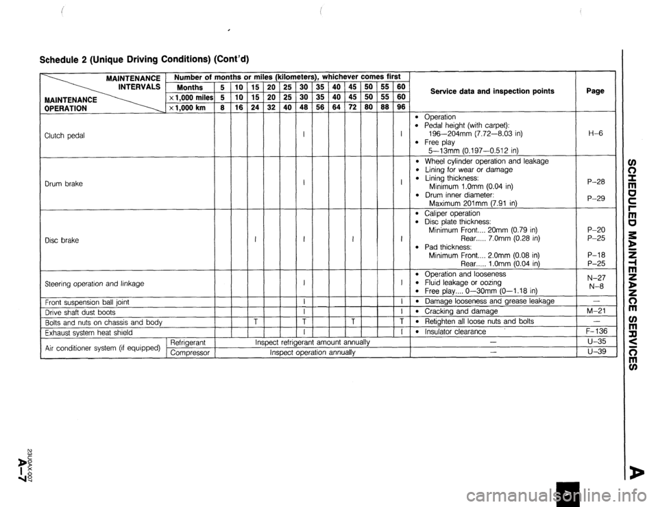
Schedule 2 (Unique Driving Conditions) (Cont’d)
(kil
I :
I :
’ 1 iii ichever comes first lometers), Y
25 30 35
25 30 35
40 48 58
I
45
45
72 50
50
80
-
-
I
I
I
I
I
T
I
,
40
iii
i5i
-
-
-
-
-
-
-
-
-
I
-
-
T -
-
-
- -
1 nspec L :t rerngeranr amount annually
Inspect operation annually m
rs
E
24
-
-
-
I
-
-
-
T
-
T fn
iiF
is
w
-
-
-
-
-
-
-
-
- iii
iii
,s
-
I
-
I
-
I
-
I
T
I-
r
T
-
T7
Service data and inspection points Page l
Operation l Pedal height (with carpet):
196-204mm (7.72-8.03 in) l
Free play
5-13mm (0.197-0.512 in) l
Wheel cylinder operation and leakage l Lining for wear or damage l Lining thickness:
Minimum l.Omm (0.04 in) l
Drum inner diameter: H-6
Clutch pedal
P-28
P-29 Drum brake
Maximum 201mm (7.91 in) l
Caliper operation l Disc plate thickness:
Minimum Front.... 20mm (0.79 in)
Rear . . . . . 7.0mm (0.28 in) l
Pad thickness:
Minimum Front.... 2.0mm (0.08 in)
Rear . . . . . 1 .Omm (0.04 in) l
Operation and looseness l Fluid leakage or oozing l Free play.... O-30mm (O-l.18 in) l
Damage looseness and grease leakage l
Cracking and damage l
Retighten all loose nuts and bolts l
Insulator clearance
-
- P-20
P-25
P-18
P-25
N-27
N-8 Disc brake
Steering operation and linkage
Front suspension ball joint
Drive shaft dust boots
Bolts and nuts on chassis and body
Exhaust system heat shield
Air conditioner system (if equipped) Refrigerant
Compressor -
M-21
-
F-136
u-35
u-39
Page 28 of 1164
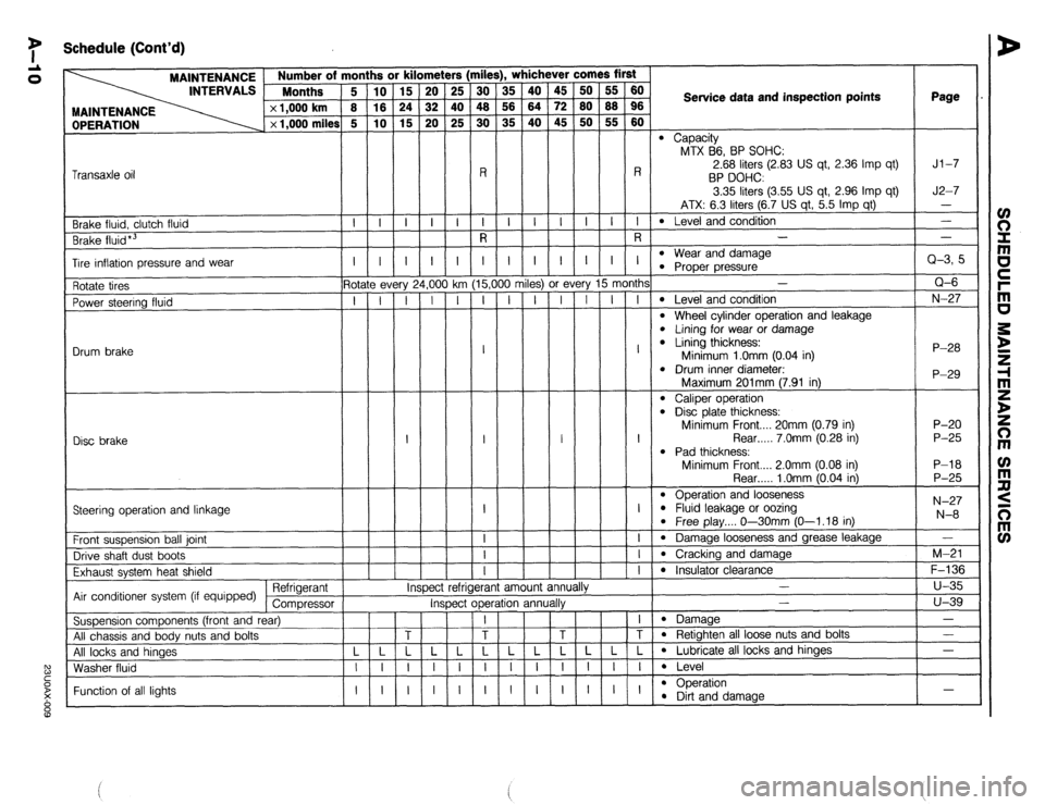
7 Schedule (Cont’d)
rile
iii
48
30
-
R
I
R !rs
25
40
25
-
-i- , whichever comes first
OPERATION MAINTENANCE Number of m
INTERVALS Months
x 1,000 km
x 1,000 miles
ii
is
G
-
i-
-
-
I
5-
T
-
-
-
-
-
-
- ii
z
ro
-
I-
-
-
I
- 45
72
45
-
-i-
-
-
I
-
ry 15 month:
I I I
A
t
A
j
milt Service data and inspection points Page
l Capacity
MTX B6, BP SOHC:
2.68 liters (2.83 US qt, 2.36 Imp qt)
BP DOHC
3.35 liters (3.55 US qt, 2.96 Imp qt)
ATX: 6.3 liters (6.7 US qt, 5.5 Imp qt)
l Level and condition
- Jl-7
J2-7
- Transaxle oil
l Wear and damaae -i- -i- -i- -
Brake fluid, clutch fluid
Brake fluid*3 -
Q-3, 5
Q-6
N-27
P-28
P-29 I I
- I
1,oo
-i
-
-
-
-
-
-
- I
G
T
-
-
-
-
-
-
- I
15,(
I Tire inflation pressure and wear l Proper pressure-
-
l Level and condition
l Wheel cylinder operation and leakage l Lining for wear or damage l Lining thickness:
Minimum 1 .Omm (0.04 in)
l Drum inner diameter. 3s) or f
I I
I
:t r
- Rotate tires
Power steering fluid
Drum brake ? every
I I
Disc brake I I
Maximum 201mm (7.91 in)
l Caliper operation l Disd plate thickness:
Minimum Front.... 20mm (0.79 in)
Rear . . . . . 7.0mm (0.28 in)
l Pad thickness:
Minimum Front.... 2.0mm (0.08 in) P-20
P-25
P-l 8
P-25
N-27
N-8 Rear . . . . . 1 .Omm (0.04 in)
l Operation and looseness l Fluid leakage or oozina
l Free play.... O--3OmmjO-1.18 in)
l Damage looseness and grease leakage
l Cracking and damage
l Insulator clearawp .-v
-
Steering operation and linkage
I
-i-
-I-
-i- Front suspension ball joint
Drive shaft dust boots
Exhaust system heat shield
Air conditioner system (if equipped) Refrigerant
Compressor
Suspension components (front and rear)
All chassis and body nuts and bolts
All locks and hinaes
Washer fluid -
M-21
F-136
u-35
u-39
-
- IY efrigerant amount ann
*. I# mspec
Inspect operation annualry -
l Damaae
l Retighten all loose nuts and bolts
l Lubricate all locks and hinges
l Level
l ODeration - Function of all lights l !%t and damage -
Page 62 of 1164
Bl REMOVAL
I 03UOBi-05 I
14
‘5
03UOBl-056
Bl-32
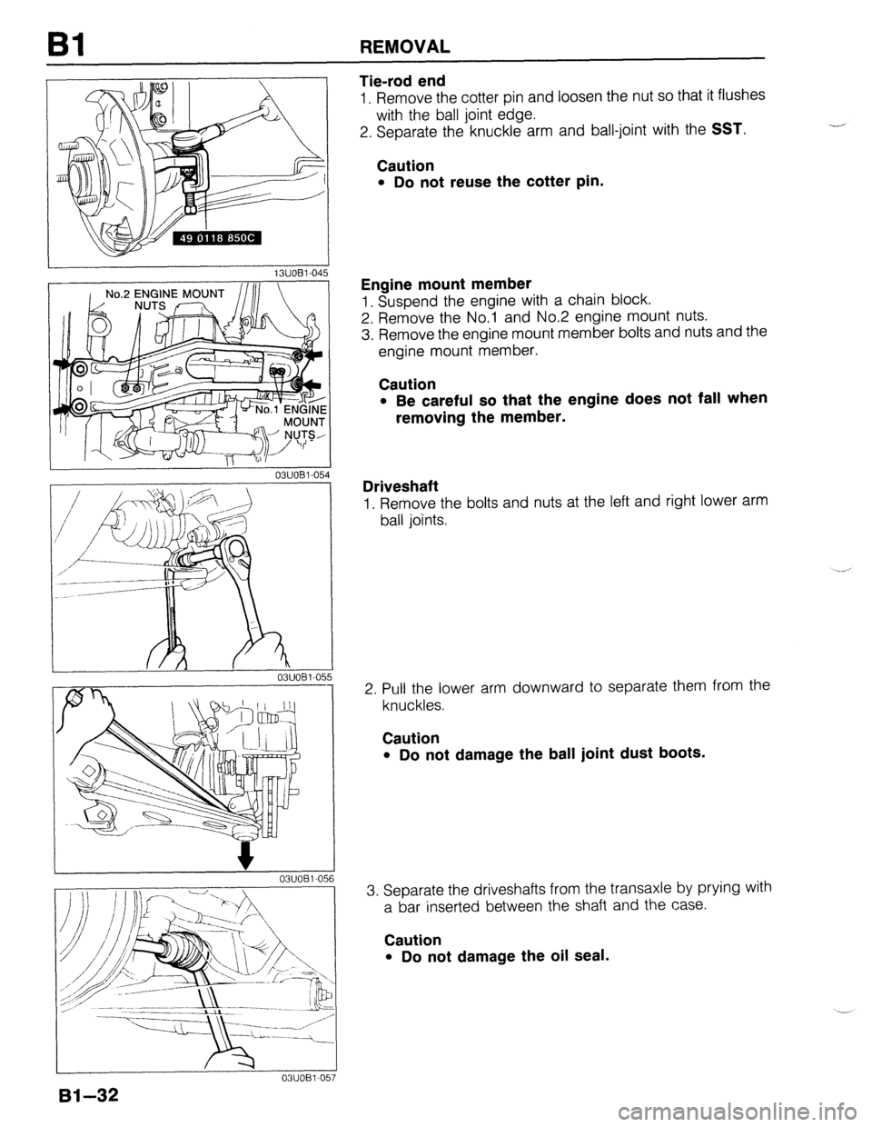
Tie-rod end
1. Remove the cotter pin and loosen the nut so that it flushes
with the ball joint edge.
2. Separate the knuckle arm and ball-joint with the
SST.
Caution
l Do not reuse the cotter pin.
Engine mount member
1. Suspend the engine with a chain block.
2. Remove the No.1 and No.2 engine mount nuts.
3. Remove the engine mount member bolts and nuts and the
engine mount member.
Caution
l Be careful so that the engine does not fall when
removing the member.
Driveshaft
1. Remove the bolts and nuts at the left and right lower arm
ball joints.
2. Pull the lower arm downward to separate them from the
knuckles.
Caution
l Do not damage the ball joint dust boots.
3. Separate the driveshafts from the transaxle by prying with
a bar inserted between the shaft and the case.
Caution
l Do not damage the oil seal.
Page 167 of 1164
REMOVAL B2
13UOB2-021
0311082-059
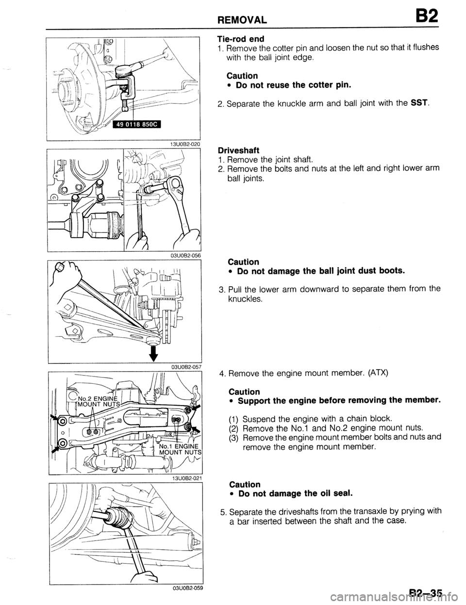
Tie-rod end
1. Remove the cotter pin and loosen the nut so that it flushes
with the ball joint edge.
Caution
l Do not reuse the cotter pin.
2. Separate the knuckle arm and ball joint with the SST.
Driveshaft
1. Remove the joint shaft.
2. Remove the bolts and nuts at the left and right lower arm
ball joints.
Caution
l Do not damage the ball joint dust boots.
3. Pull the lower arm downward to separate them from the
knuckles.
4. Remove the engine mount member. (ATX)
Caution
l Support the engine before removing the member.
(1) Suspend the engine with a chain block.
(2) Remove the No.1 and No.2 engine mount nuts.
(3) Remove the engine mount member bolts and nuts and
remove the engine mount member.
Caution
l Do not damage the oil seal.
5. Separate the driveshafts from the transaxle by prying with
a bar inserted between the shaft and the case.
B2-35
Page 458 of 1164
G IGNITION SYSTEM
-.-.. .----___ 03UOGX-042
03UOGX-04
--.---- J
03UOGX-044
WEAR AND CARBON
/
c- -BURNT
PLUG GAP
L--
c
DAMAGE AND
,llllll....*llll,lllf DETERIORATIOF
; -,DAMAGE
03UOGX.04
G-18
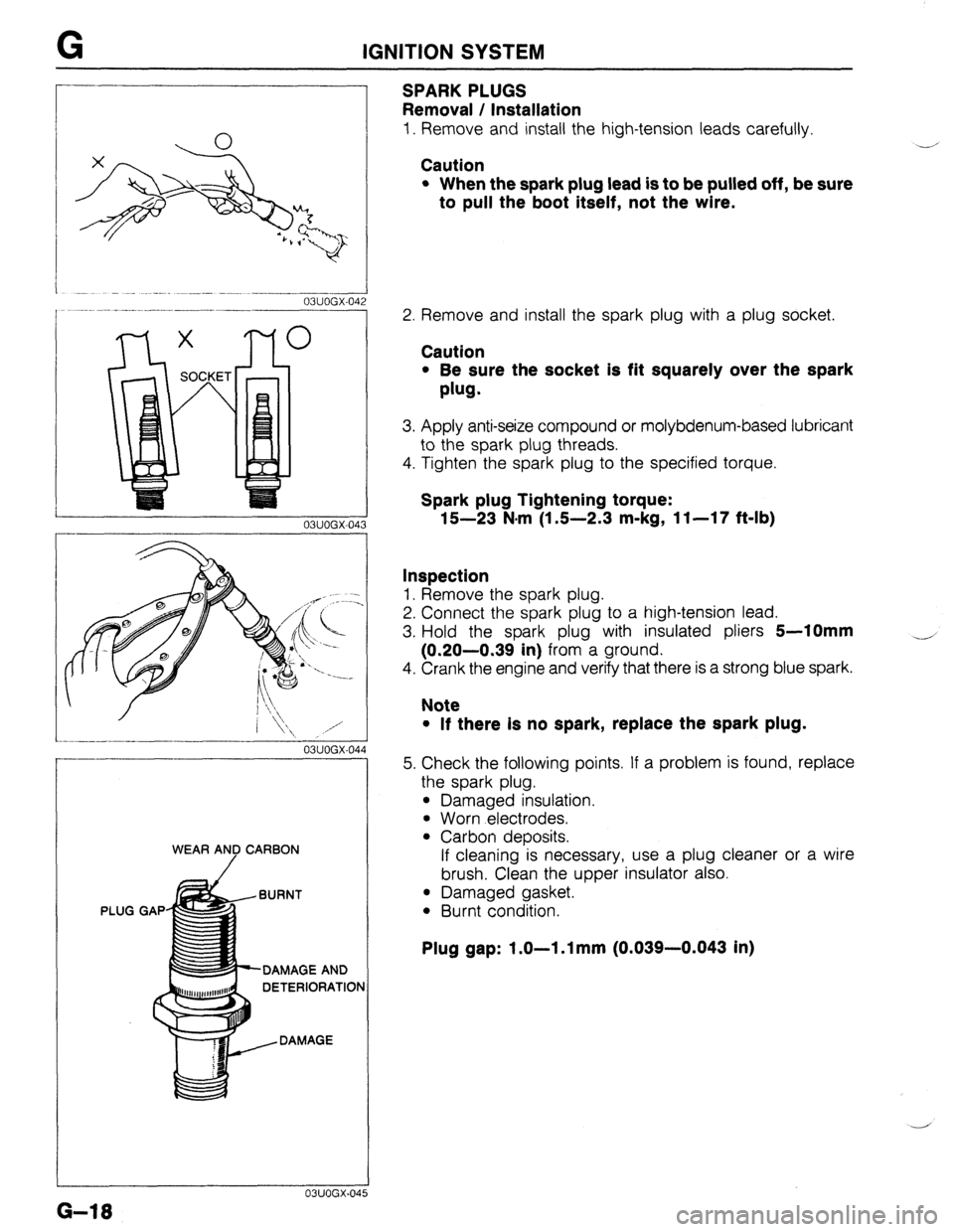
SPARKPLUGS
Removal / Installation
1. Remove and install the high-tension leads carefully.
Caution
l When the spark plug lead is to be pulled off, be sure
to pull the boot itself, not the wire.
Y’
2. Remove and install the spark plug with a plug socket.
Caution
l Be sure the socket is fit squarely over the spark
plug.
3. Apply anti-seize compound or molybdenum-based lubricant
to the spark plug threads.
4. Tighten the spark plug to the specified torque.
Spark plug Tightening torque:
15-23 N.m (1 S-2.3 m-kg, 11-17 f&lb)
Inspection
1. Remove the spark plug.
2. Connect the spark plug to a high-tension lead.
3. Hold the spark plug with insulated pliers
5-10mm
(0.20-0.39 in) from a ground.
4. Crank the engine and verify that there is a strong blue spark.
4
Note
l If there Is no spark, replace the spark plug.
5. Check the following points. If a problem is found, replace
the spark plug.
l Damaged insulation.
l Worn electrodes.
l Carbon deposits.
If cleaning is necessary, use a plug cleaner or a wire
brush. Clean the upper insulator also.
l Damaged gasket.
l Burnt condition.
Plug gap: 1.0-l .l mm (0.039-0.043 in)
Page 484 of 1164
H CLUTCH RELEASE CYLINDER
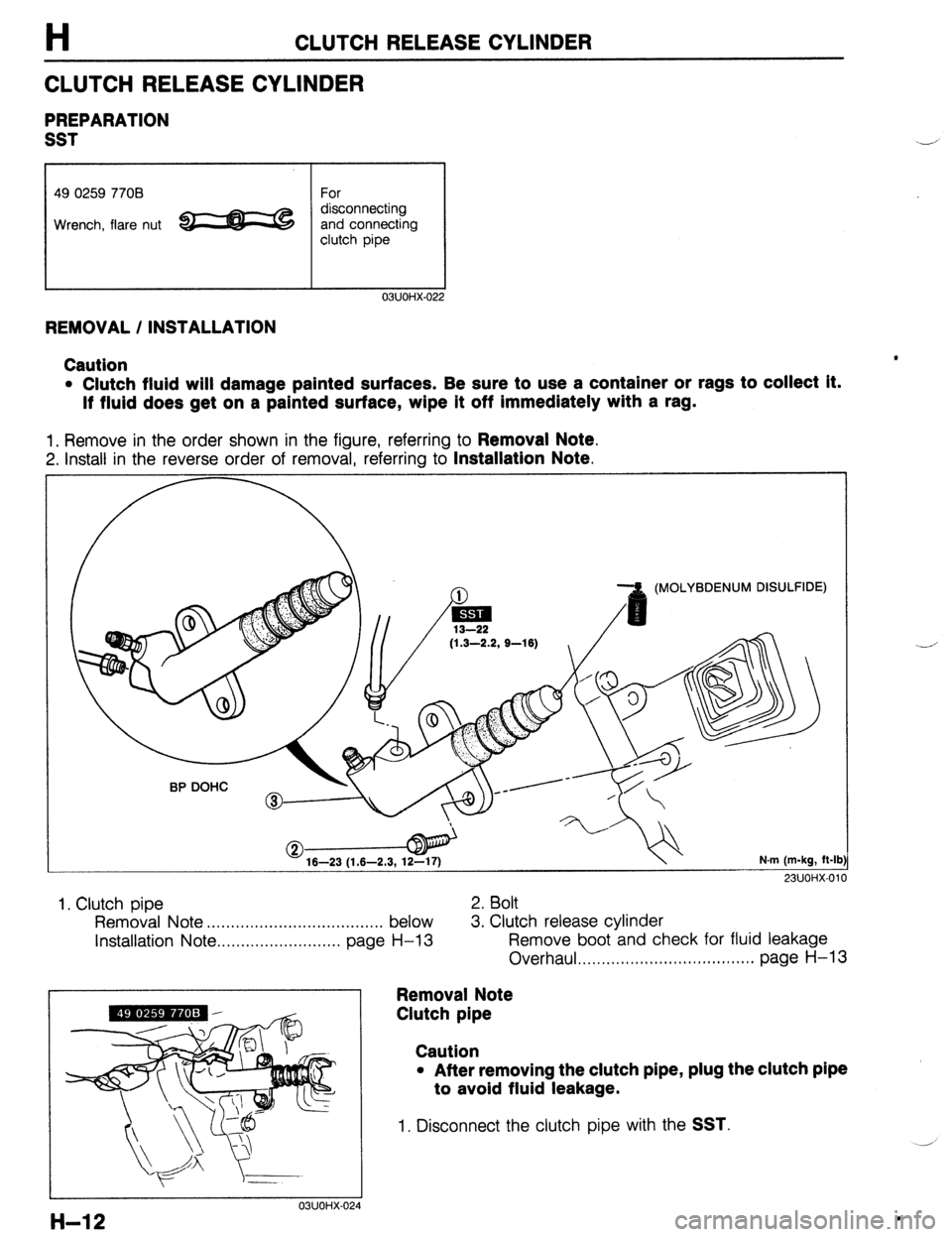
CLUTCH RELEASE CYLINDER
PREPARATION
SST
49 0259 7708 For
Wrench, flare nut e c$on;;;;;!&
clutch pipe
03UOHX-022
REMOVAL / INSTALLATION
Caution
l Clutch fluid will damage painted surfaces. Be sure to use a container or rags to collect it.
If fluid does get on a painted surface, wipe it off immediately with a rag.
1. Remove in the order shown in the figure, referring to Removal Note.
2. Install in the reverse order of removal, referring to Installation Note.
(MOLYBDENUM DISULFIDE)
(1.3-2.2, S-16)
16-23 (1.6-2.3, 12-17) N.m (m-kg, ft-lb
23UOi-K011
1, Clutch pipe 2. Bolt
Removal Note . . . . . . . . . . . . . . . . . . . . . . . ,........... . . below 3. Clutch release cylinder
installation Note . . . . . . . . . . . . . . . . . . . . . . . . . . page
H-13 Remove boot and check for fluid leakage
Overhaul . . . . . . . . . . . . . . . . . . . . . . . . . . . . . . . . ...*. page H-13
Removal Note
Clutch pipe
03UOHX-024
Caution
l After removing the clutch pipe, plug the clutch pipe
to avoid fluid leakage.
1. Disconnect the clutch pipe with the SST.
H-12 .
Page 485 of 1164
CLUTCH RELEASE CYLINDER
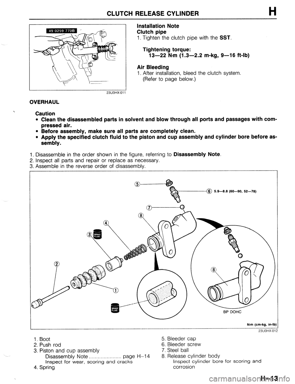
Installation Note
Clutch pipe
H
1. Tighten the clutch pipe with the SST.
Tightening torque:
13-22 N-m (1.3-2.2 m-kg, 9-16 ft-lb)
Air Bleeding
1. After installation, bleed the clutch system.
(Refer to page below.)
23UOHX-011
OVERHAUL
Caution
l Clean the disassembled parts in solvent and blow through all ports and passages with com-
pressed air.
l Before assembly, make sure all parts are completely clean.
l Apply the specified clutch fluid to the piston and cup assembly and cylinder bore before as-
sembly.
1. Disassemble in the order shown in the figure, referring to Disassembly Note.
2. Inspect all parts and repair or replace as necessary.
3. Assemble in the reverse order of disassembly.
@ 5.9-8.8 (60-90, 52-78)
N.m (cm-kg, in-lb)
23UOHX-012
1. Boot 5. Bleeder cap
2. Push rod 6. Bleeder screw
3. Piston and cup assembly 7. Steel ball
Disassembly Note . . . . . . . . . . . . . . . . . . . . . . page H-l 4 8. Release cylinder body
Inspect for wear, scoring
and cracks inspect cylinder bore for scoring and
4. Spring corrosion
H-13
Page 487 of 1164
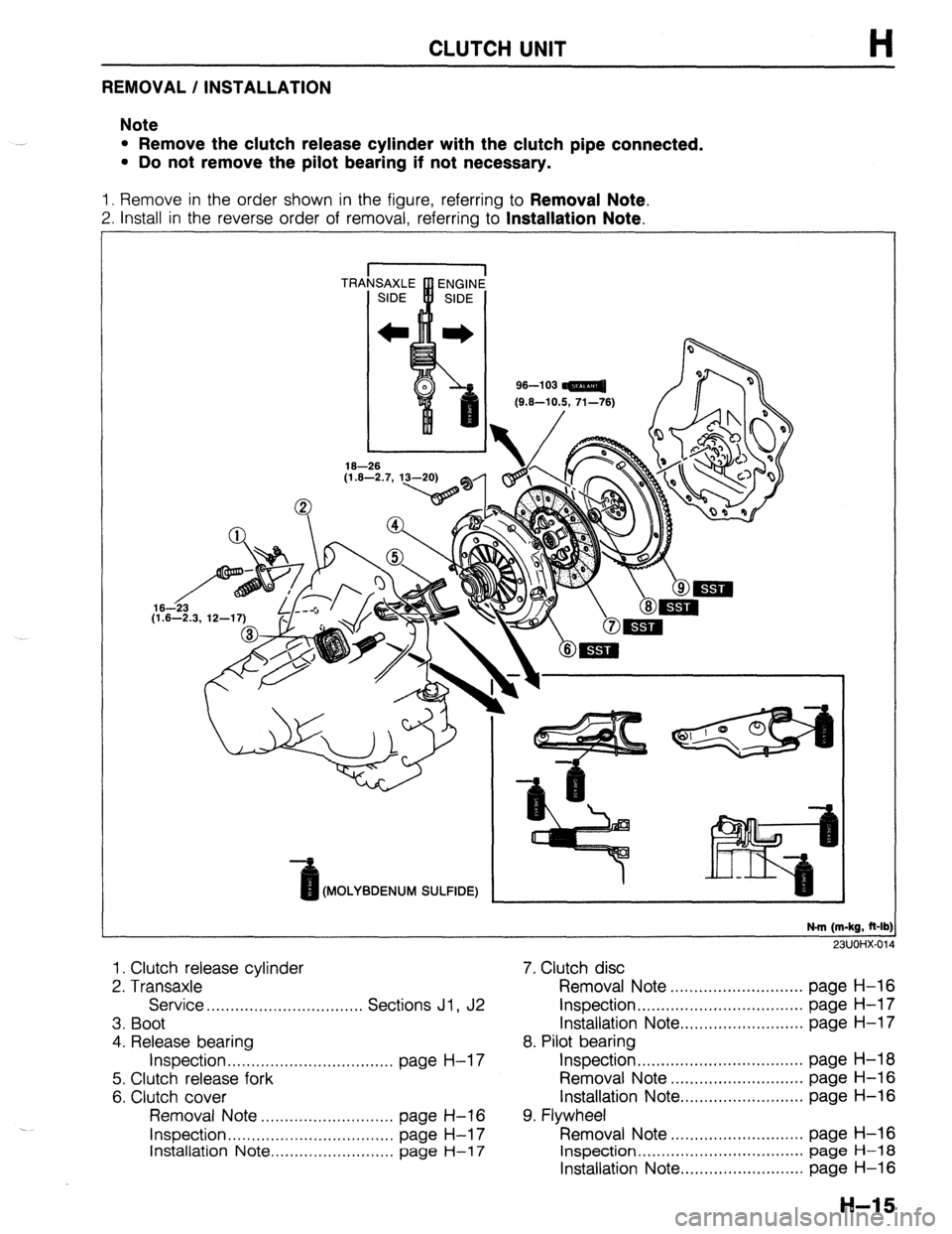
CLUTCH UNIT
REMOVAL / INSTALLATION
Note
l Remove the clutch release cylinder with the clutch pipe connected.
l Do not remove the pilot bearing if not necessary.
1. Remove in the order shown in the figure, referring to Removal Note.
2. Install in the reverse order of removal, referring to Installation Note.
96-l 03
Kt.6-10.5. 71-761
(MOLYBDENUM SULFIDE)
N-m (m-kg, R-lb:
911 Im-4Y.fi,r
1. Clutch release cylinder
2. Transaxle
Service . . . . . . . . . . . . . . . . . . . . . . . . . ,....... Sections Jl , J2
3. Boot
4. Release bearing
Inspection . . . . . . . . . . . . . . . . . . . . . . . . . . . . . . . . . . . page H-l 7
5. Clutch release fork
6. Clutch cover
Removal Note ..,...........,,,.........,, page H-16
Inspection . . . . . . . . . . . . . . . . . . . . . . . . . . . . . . . . . . . page H-l 7
Installation Note .,......................., page
H-l 7
7. Clutch disc
Removal Note ............................ page H-16
Inspection.. ................................. page H-l 7
Installation Note .......................... page H-l 7
8. Pilot bearing
Inspection ................................... page H-18
Removal Note ............................ page H-16
Installation Note.. ........................ page H-16
9. Flywheel
Removal Note ............................ page H-16
Inspection ................................... page H-18
Installation Note .......................... page H-16
H-15
Page 502 of 1164
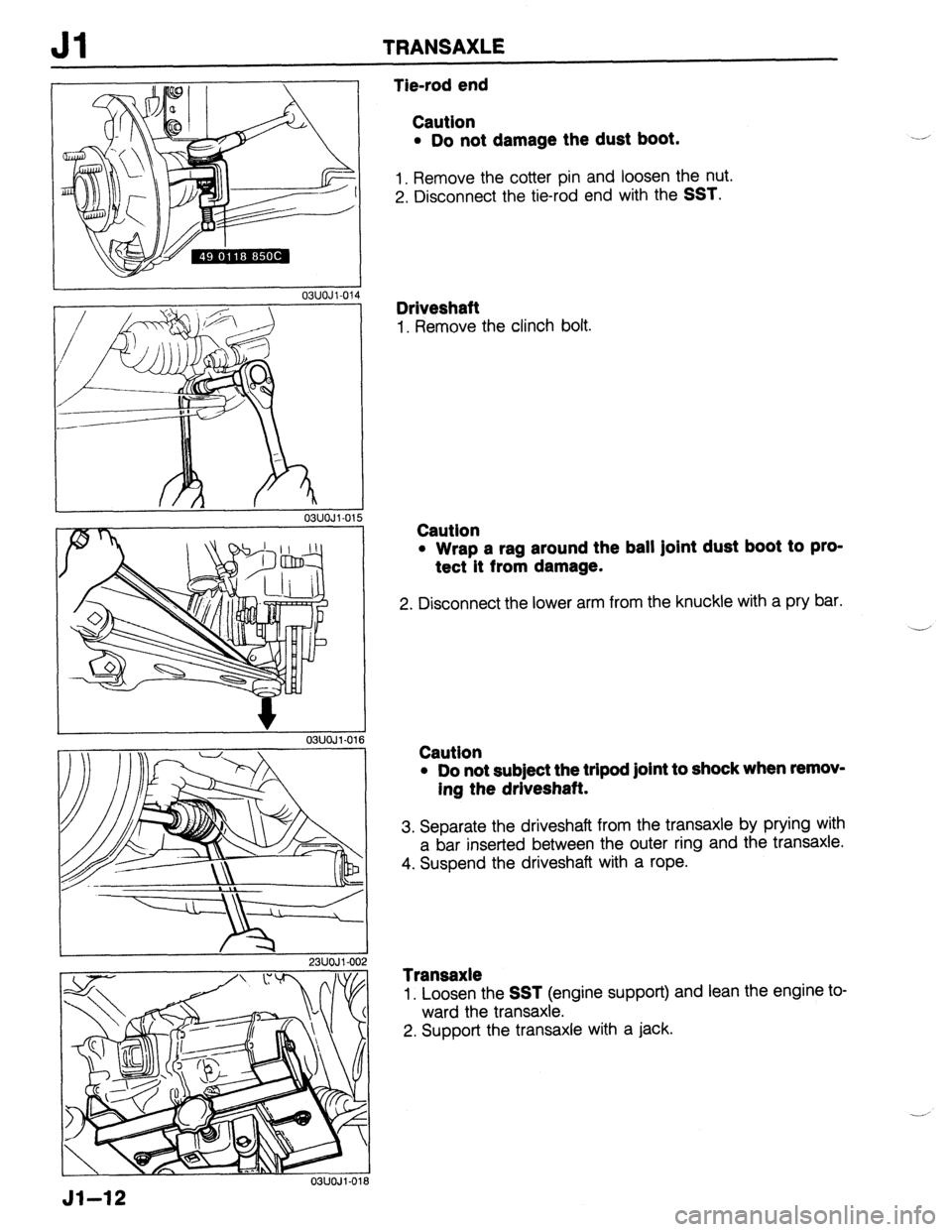
Jl TRANSAXLE
L
r
r
23UOJl-002
03lJOJl-016
Tie-rod end
Caution
l Do not damage the dust boot.
1. Remove the cotter pin and loosen the nut.
2. Disconnect the tie-rod end with the
SST.
Driveshaft
1. Remove the clinch bolt.
Caution
l Wrap a rag around the ball Joint dust boot to pro-
tect it from damage.
2. Disconnect the lower arm from the knuckle with a pry bar.
.-’
Caution
l Do not sub]ect the tripod joint to shock when remov-
ing the driveshaft.
3. Separate the driveshaft from the transaxle by prying with
a bar inserted between the outer ring and the transaxle.
4. Suspend the driveshaft with a rope.
Transaxle
1. Loosen the SST (engine support) and lean the engine to-
ward the transaxle.
2. Support the transaxle with a jack.
Jl-12