oil MAZDA PROTEGE 1992 Owners Manual
[x] Cancel search | Manufacturer: MAZDA, Model Year: 1992, Model line: PROTEGE, Model: MAZDA PROTEGE 1992Pages: 1164, PDF Size: 81.9 MB
Page 182 of 1164

82 DISASSEMBLY
-. 05UOBX-10
-
REAR COVER
-.
05UOBX-10
Main bearing support plate (MBSP)
1, Remove the MBSP mounting bolts.
Caution
l Do not damage or scratch the contact surfaces
when removing the old sealant.
2. Insert a screwdriver or a suitable tool at the points shown
in the figure.
3. Remove the MBSP.
Front oil seal
1. Remove the oil seal with a screwdriver protected with a rag.
Rear oil seal
1. Remove the oil seal with a screwdriver protected with a rag.
92-50
Page 183 of 1164

B2
CYLINDER BLOCK (INTERNAL PARTS)
1. Disassemble in the order shown in the fioure, referring to Disassembly Note.
I. Connecting rod cap 7. Piston
Disassembly Note ,..,.,., ,.,..... ,, ,. page B2-52 Inspection ,.. . . ,.. . . . . . . . . . page 82-62
2. Connecting rod 8. Main bearing cap
Disassembly Note ..,.. . . . . . . ,. page B2-52 Disassembly Note .,,,..,..,...... ~.,. page 82-53
Inspection . . . . . . . . . . . . . . . . . . . . . . . page B2-63 9. Crankshaft
3. Connecting rod bearing Disassembly Note ,... . . . . . . page 92-53
Inspection . . . . . . . . . . . . . . . . . . . . . . . . . . . . . . . . . page B2-64 Inspection ,......,,.,._.................... page B2-64
4. Piston ring 10. Main bearing
Disassembly Note .,...........,.,..,. page B2-52 Inspection ., ,... . . . page B2-64
Inspection ..~ ,., . . . . . . . . . page B2-62 Il. Thrust bearing
5. Piston pin clip 12. Oil jet
6. Piston pin Inspection ,..,..,., ,..,.., . . . . . . . . . . . . . . . . page B2-61
Disassembly Note ,.. . . . . . . page B2-52 13. Cylinder block
Inspection . . . . . . . . . . . . . . . . . . . . . . . . . . . . page 82-63 Inspection . . . . . . . . . . . . . . . . . . . . . . . . . . . . . . . . . page B2-60
B2-51
Page 184 of 1164

82 DISASSEMBLY
03UOB2-071 6
- ____-______---..----. 05UOBX 113
------ -__ .---
7
Disassembly Note
Connecting rod cap
1. Before removing the connecting rod caps, measure the con-
necting rod side clearance. (Refer to page B2-71.) 1
Connecting rod
1. Before removing the connecting rods, measure the connect-
ing rod oil clearance. (Refer to page B2-71.)
2. Remove the Plastigage from the crankpin journals,
Caution
l Do not scratch the crankshaft journal or the cylin-
der wall.
-,
3. Use the handle of a hammer to remove the piston and con-
necting rod assembly through the top of the cylinder block.
Piston ring
Caution
l Do not apply excessive tension, which may cause
the rings to snap out.
1. Remove the piston rings with a piston ring expander (com-
mercially available).
Piston pin
1. Remove the piston pin with the SST.
Page 185 of 1164

DISASSEMBLY
03UOBZO7i
Main bearing cap
1. Before removing the main bearing caps, measure the crank-
shaft end play. (Refer to page 62-70.)
2. Loosen the main bearing cap bolts in two or three steps
in the order shown in the figure.
3. Remove the main bearing caps.
Crankshaft
1. Before removing the crankshaft, measure the main bear-
ing oil clearances. (Refer to page 82-69.)
03UOB2-079
B2-53
Page 186 of 1164

I32 INSPECTION / REPAIR
INSPECTION / REPAIR
PREPARATION
SST
49 6012 005 49 6012 005
Remover & Remover &
installer, valve installer, valve
guide guide
49 LO12 002
Body
(Part of
49 LO12 OAO)
49 LO12 004
Nut
(Part of
49 LO12 OAO) For
removal of
valve guide
For
installation of
valve guide
For
installation of
valve guide 49 LO12 OAO
Installer set,
valve seal &
valve guide
49 LO12 003
Installer
(Part of
49 LO12 OAO) For
installation of
valve guide
For
installation of
valve guide
05UOBX-1
1. Clean all parts, being sure to remove all gasket fragments, dirt, oil or grease, carbon, moisture residue,
and other foreign materials.
2. Inspection and repairs must be performed in the order specified. -.,
Caution
l Do not damage the joints or friction surfaces of aluminum alloy components (such as the cyl-
inder head or pistons).
0311082-162
03UOB2-70 OWOBX-119
CYLINDER HEAD
1, Inspect the cylinder head for damage, cracks, and leakage
of water and oil. Replace the cylinder head if necessary.
2. Measure the cylinder head distortion in the six directions
shown in the figure.
Distortion: O.lOmm (0.004 in) max.
Cautlon
l Before grinding the cylinder head, check the follow-
ing and repair or replace the cylinder head as
necessary.
Sinking of valve seats
Damage of manifold contact surface
Camshaft oil clearances and end play
3. If the cylinder head distortion exceeds specification, grind
the cylinder head surface.
If the cylinder head height is not within specification, replace
it. Height: 133.8-l 34.0mm (5.268-5.276
in)
Grinding: O.lOmm (0.004 in) max.
62-64
Page 191 of 1164
INSPECTION / REPAIR B2
23UOB2-06
051JOBX.14
05UOBX.14
OWOBX-14
05UOBX-14
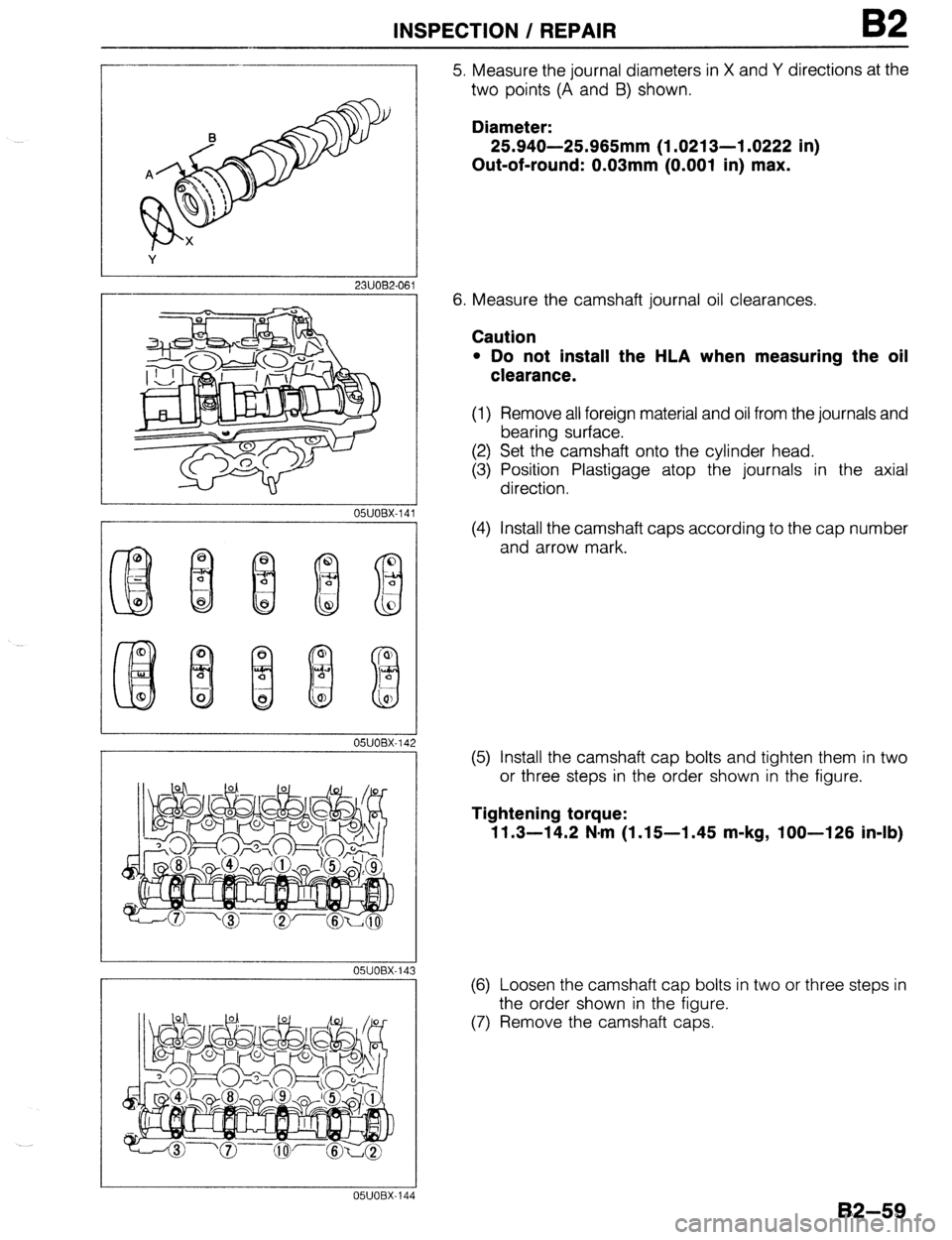
5. Measure the journal diameters in X and Y directions at the
two points (A and 8) shown.
Diameter:
25.940-25.965mm (1.0213-l .0222 in)
Out-of-round: 0.03mm (0.001 in) max.
6. Measure the camshaft journal oil clearances.
Caution
l Do not install the HLA when measuring the oil
clearance.
(1) Remove all foreign material and oil from the journals and
bearing surface.
(2) Set the camshaft onto the cylinder head.
(3) Position Plastigage atop the journals in the axial
direction.
(4) Install the camshaft caps according to the cap number
and arrow mark.
(5) Install the camshaft cap bolts and tighten them in two
or three steps in the order shown in the figure.
Tightening torque:
11.3-14.2 N-m (1.15-l .45 m-kg, loo-126 in-lb)
(6) Loosen the camshaft cap bolts in two or three steps in
the order shown in the figure.
(7) Remove the camshaft caps.
82-59
Page 192 of 1164
B2 INSPECTION / REPAIR
r--
1
05UOBX-14
I -
L
05UOBX-149
82-60
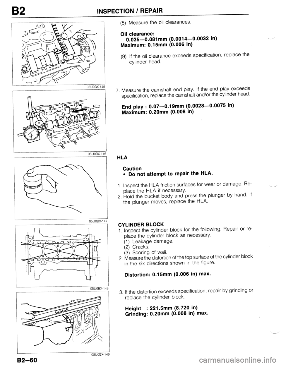
(8) Measure the oil clearances.
Oil clearance:
0.035-0.081 mm (0.0014-0.0032 in)
Maximum: 0.15mm (0.006 in)
(9) If the oil clearance exceeds specification, replace the
cylinder head.
7. Measure the camshaft end play. If the end play exceeds
specification, replace the camshaft and/or the cylinder head.
End play : 0.07-0.19mm (0.0028-0.0075 in)
Maximum: 0.20mm (0.008 in)
HLA
Caution
l Do not attempt to repair the HLA.
1, Inspect the HLA friction surfaces for wear or damage. Re-
place the HLA if necessary.
2. Hold the bucket body and press the plunger by hand. If
the plunger moves, replace the HLA.
CYLINDER BLOCK
1. Inspect the cylinder block for the following. Repair or re-
place the cylinder block as necessary.
(1) ‘Leakage damage.
(2) Cracks.
(3j Scoring of wall.
2. Measure the distortion of the top surface of the cylinder block
in the six directions shown in the figure.
Distortion: 0.15mm (0.006 in) max.
3. If the distortion exceeds specification, repair by grinding’or
replace the cylinder block.
Height : 221 Smm (8.720 in)
Grinding: 0.20mm (0.008 in) max.
Page 193 of 1164
INSPECTION / REPAIR B2
A ,-
B
C
I
03UOB2-099
OWOBX-151
1
I
OSJOBX-15
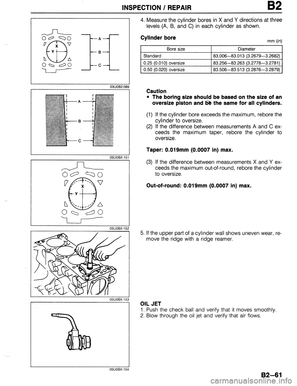
4. Measure the cylinder bores in X and Y directions at three
levels (A, B, and C) in each cylinder as shown.
Cylinder bore
Bore size
Standard
0.25 (0.010) oversize
0.50 (0.020) oversize mm (in)
Diameter
83.006-83.013 (3.2679-3.2682)
83.256-83.263 (3.2778-3.2781)
83.506-83.513 (3.2876-3.2879)
Caution
l The boring size should be based on the size of an
oversize piston and 643 the same for all cylinders.
(1) If the cylinder bore exceeds the maximum, rebore the
cylinder to oversize.
(2) If the difference between measurements A and C ex-
ceeds the maximum taper, rebore the cylinder to
oversize.
Taper: 0.019mm (0.0007 in) max.
(3) If the difference between measurements X and Y ex-
ceeds the maximum out-of-round, rebore the cylinder
to oversize.
Out-of-round: 0.019mm (0.0007 in) max.
5. If the upper part of a cylinder wall shows uneven wear, re-
move the ridge with a ridge reamer.
OIL JET
1. Push the check ball and verify that it moves smoothly.
2. Blow through the oil jet and verify that air flows.
05UOBX-15
82-61
Page 194 of 1164
B2 INSPECTION / REPAIR
OIL RIN
GROOV
16Smm
(0.650 in
UTER DIAMETER
Caution
l If the piston Is replaced, the plston rings must also
be replaced.
03UOB2-090
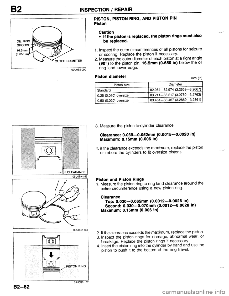
1. Inspect the outer circumferences of all pistons for seizure
or scoring. Replace the piston if necessary.
2. Measure the outer diameter of each piston at a right angle
(90°) to the piston pin,
16.5mm (0.650 In) below the oil
ring land lower cage.
--It- CLEARANCE
OSUOBX- 156
03UOB2-16 3
PISTON RING
7
PISTON, PISTON RING, AND PISTON PIN
Piston
Plston diameter
mm (in)
Piston size
Standard
0.25 (0.010) oversize
0.50 (0.020)
oversize Diameter
82.954-82.974 (3.2659-3.2667)
83.211-83.217 (3.2760-3.2763)
83.461-83.467 (3.2859-3.2861)
3. Measure the piston-to-cylinder clearance.
Clearance: 0.039-0.052mm (0.0015--0.0020 in)
Maxlmum: 0.15mm (0.006 In)
4. If the clearance exceeds the maximum, replace the piston
or rebore the cylinders to fit oversize pistons.
Piston and Piston Rings
1. Measure the piston ring to ring land clearance around the
entire circumference using a new piston ring.
Clearance
Top: 0.030-0.065mm (0.0012-0.0026 in)
Second: 0.030-0.070mm (0.0012-0.0026 in)
Maximum: 0.15mm (0.006 in)
2. If the clearance exceeds the maximum, replace the piston.
3. Inspect the piston rings for damage, abnormal wear, or
breakage. Replace the piston rings if necessary.
4. Insert the piston ring into the cylinder by hand and use the
piston to push it to the bottom of the ring travel.
B2-62
Page 195 of 1164
INSPECTION / REPAIR 82
05UOBX-160
i OBX-162
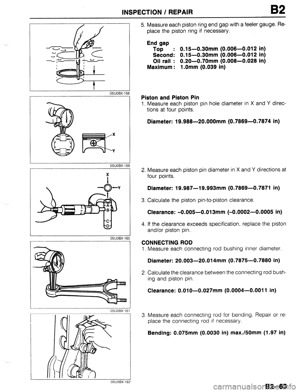
5. Measure each piston ring end gap with a feeler gauge. Re-
place the piston ring if necessary.
End gap
Top : 0.15-0.30mm (0.006-0.012 in)
Second: 0.15-0.30mm (0.006-0.012 in)
Oil rail : 0.20-0.70mm (0.006-0.026 in)
Maximum : l.Omm (0.039 in)
Piston and Piston Pin
1. Measure each piston pin hole diameter in X and Y direc-
tions at four points.
Diameter: 19.968-20.000mm (0.7869-0.7874 in)
2. Measure each piston pin diameter in X and Y directions at
four points.
Diameter: 19.987-19.993mm (0.7869-0.7871 in)
3. Calculate the piston pin-to-piston clearance.
Clearance: -0.005-0.013mm (-0.0002-0.0005 in)
4. If the clearance exceeds specification, replace the piston
and/or piston pin.
CONNECTING ROD
1. Measure each connecting rod bushing inner diameter.
Diameter: 20.003-20.014mm (0.7875-0.7880 in)
2. Calculate the clearance between the connecting rod bush-
ing and piston pin.
Clearance: O.OlO-0.027mm (0.0004-0.0011 in)
3. Measure each connecting rod for bending. Repair or re-
place the connecting rod if necessary.
Bending: 0.075mm (0.0030 in) max./fiOmm (1.97 in)
82-63