fuse MAZDA PROTEGE 1992 User Guide
[x] Cancel search | Manufacturer: MAZDA, Model Year: 1992, Model line: PROTEGE, Model: MAZDA PROTEGE 1992Pages: 1164, PDF Size: 81.9 MB
Page 806 of 1164

WINDSHIELD WIPER AND WASHER
Intermittent function does not operate
(With wiper relay)*
i
Disconnect wiper relay connector;
check for continuity of terminal-wire (B) to ground
I Repair harness (Wiper relay-Ground)
OK
=j Replace wiper relay (Refer to Section T)
*: U.S. with/without cruise control, Canada with cruise control
03uosx-119
Intermittent function does not operate
(Without wiper relay)*
1
Disconnect wiper switch connector;
check for continuity of terminal-wire (B) to ground Repair harness (Wiper switch-Ground)
*: Canada without cruise control
Washer does not operate (Wiper operates OK)
1
I
wiper 1 -
repay Check for battery voltage at terminal-wire
Repair harness (Fuse box-Wiper switch) l
1 (L) of wiper switch connector J
1 OK
Check for battery voltage at terminal-wire (L/O) of
washer switch connector with washer switch ON Check washer switch (Refer to page S-71)
1
1 OK
Disconnect washer motor connector;
check for battery voltage at terminal-wire (L/O) with
washer switch ON Repair harness (Washer switch-Washer motor)
Check for continuity of above connector terminal-wire
(B) to ground Repair harness (Washer motor-Ground)
*l: Canada without cruise control
*2: U.S. with/without cruise control, Canada with cruise control
23UOSX-020
WIPER MOTOR
Inspection
Conductivity check
1. Disconnect the wiper motor connector.
2. Check for continuity between terminals with an ohmmeter.
--iizzs
In automatic park
Out automatic park
o---O: Indicates continuity
Page 811 of 1164

REAR WIPER AND WASHER S
Rear wiper does not operate
Check REAR WIPER 10A NG
= Repair harness and replace fuse
Turn ignition switch ON t
Check for battery voltage at terminal-wire (L/G) of rear NG
wiper motor connector Repair harness (Fuse-Rear wiper motor)
I
OK
I
Check for battery voltage at terminal-wire (L/B) of rear
wiper motor connector
I NG-
- Check rear wiper motor (Refer to page S-77)
OK
6
Remove the CPU
Check for battery voltage at B wire of the joint box (CPU) Repair harness (CPU-Rear wiper motor)
Check for OV at F wire of th Repair harness (CPU-Rear wiper switch)
Disconnect the rear wiper switch connector
Check for continuity of terminal-wire (B) to ground
I Repair harness (Rear wiper switch-Body ground)
OK
Check the rear wiper switch (Pi
Replace rear wiper switch
OK
- Replace CPU
J
23UOSX-025
Rear wiper automatic park function does not work t
Check continuity between rear wiper motor body and
ground Repair ground circuit of motor body
OK
Check rear wiper motor (Ref
I Replace rear wiper motor
23UOSX-026
s-75
Page 812 of 1164

REAR WIPER AND WASHER
Rear wiper does not stop when switch turned OFF
I -
Turn ignition switch ON and operate motor
I
Verify that wiper stops when connector disconnected
from rear wiper switch Check rear wiper switch (Refer to page S-77) NG
Disconnect connector from rear wiper motor;
check for no continuity of terminal-wire (L/B) of harness
side connector to ground Repair harness (Rear wiper motor-Rear wiper switch)
Check rear wiper motor (Re NG
Replace rear wiper motor
Replace CPU
23UOSX.027 Rear washer motor does not operate
(Rear wiper operates OK)
Check METER 15A fuse
Repair harness and replace fuse
Turn ignition switch ON
I
Check for battery voltage at terminal-wire (B/Y) of rear
NG
washer motor Repair harness (Fuse-Rear washer motor)
I
Check for battery voltage at terminal-wire (0) of rear
washer motor
t Check rear washer motor (Refer to page S-77)
1 OK
Check for battery voltage at terminal-wire (0) of rear
washer switch
I NG
_ Repair harness (Rear washer motor-Rear washer
switch)
Check rear washer switch (R
Replace rear washer switch
23UOSX.028
S-76
Page 817 of 1164

SLIDING SUNROOF
Sliding sunroof does not operate
NG
Check SUNROOF 15A fuse = Repair harness and replace fuse OK
Turn ignition switch ON t
Check for battery voltage at terminal-wire (G/O) of sun-
roof switch connector NG-
_ Repair harness (Fuse box - Sunroof switch)
I OK
Check for battery voltage at terminal-wire (G) of sunroof
relay connector NG
- Repair harness (Sunroof switch-Sunroof relay) OK
Disconnect sunroof relay; check for continuity terminal-
wire (B) to ground NG
Repair harness (Sunroof relay - Motor body ground)
1 OK
Check sunroof relay (Refer to page S-82)
I Replace sunroof relay (Refer to page S-82)
1 OK
Disconnect motor connector; check for continuity be-
tween terminal-wires (L, Y, Y/R, Y/G) of sunroof relay
and motor connectors
I NG
- Repair harness (Sunroof relay - Motor) OK
Check motor assembly (Refer
I NG - Replace motor assembly (Refer to page S-81)
1 OK
Disconnect sunroof switch connectors; check for con-
tinuity between terminal-wires (L, L/W, L/G, L/Y, B) of
sunroof switch and motor connectors Repair harness (Sunroof switch - Motor)
23UOSX-033
MOTOR ASSEMBLY
Inspection
Motor
1. Disconnect the motor connector.
2. Verify that the motor operates when battery voltage is con-
nected to terminal (i) and a ground is connected to termi-
nal (j).
3. Reverse the above connections and verify reverse opera-
tion of the motor.
I I
23UOSX-034
S-81
Page 841 of 1164

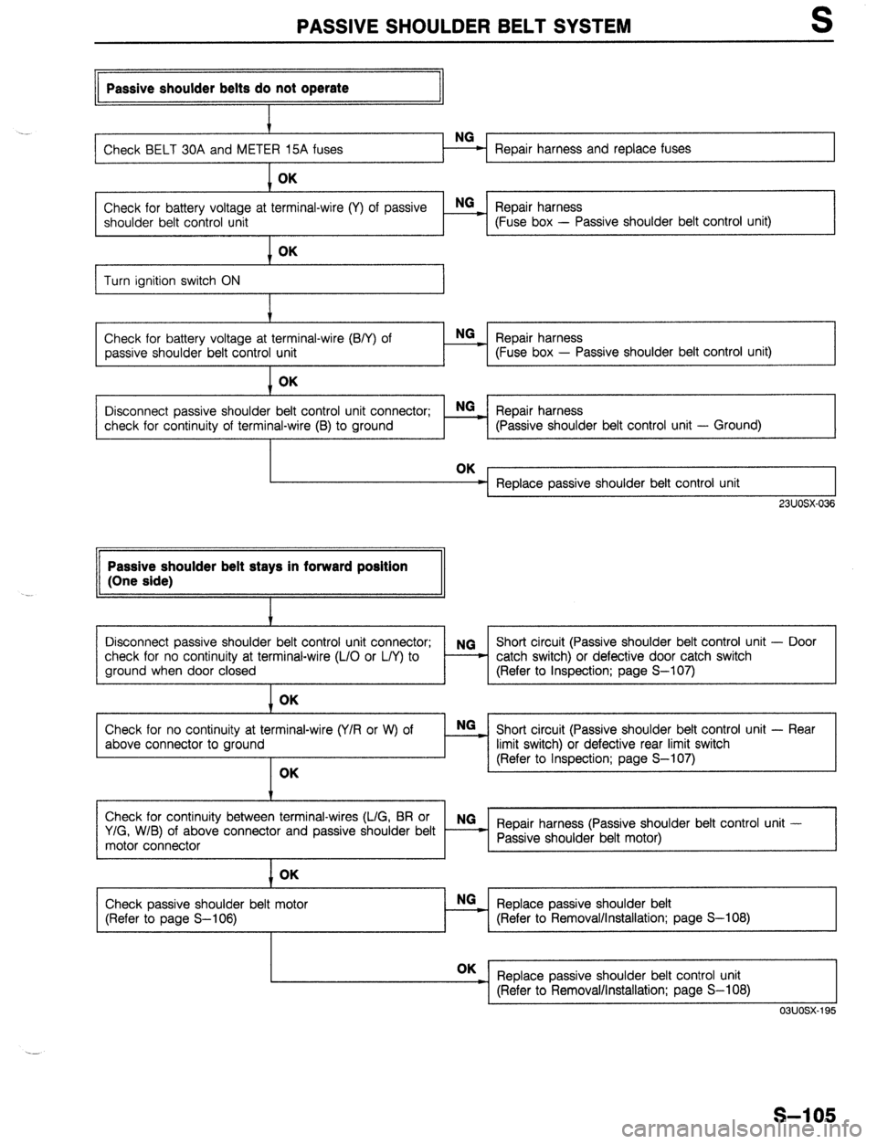
PASSIVE SHOULDER BELT SYSTEM S
II Passive shoulder belts do not operate
II
. .
Repair harness and replace fuses OK
Check for battery voltage at terminal-wire (Y) of passive E Repair harness
shoulder belt control unit (Fuse box - Passive shoulder belt control unit)
I
Turn ignition switch ON
Check for battery voltage at terminal-wire (B/Y) of
passive shoulder belt control unit OK
NG
Repair harness _
- (Fuse box - Passive shoulder belt control unit)
Disconnect passive shoulder belt control unit connector; NGz Repair harness
check for continuity of terminal-wire (B) to ground (Passive shoulder belt control unit - Ground)
Replace passive shoulder belt control unit
, 23UOSX-036 Passive shoulder belt stays in forward position
(One side)
I
Disconnect passive shoulder belt control unit connector; NG Short circuit (Passive shoulder belt control unit - Door
check for no continuity at terminal-wire (L/O or L/Y) to - - catch switch) or defective door catch switch
ground when door closed (Refer to Inspection; page S-107) OK
Check for no continuity at terminal-wire (Y/R or W) of
above connector to ground OK E Short circuit (Passive shoulder belt control unit - Rear
limit switch) or defective rear limit switch
(Refer to Inspection; page S-107)
Check for continuity between terminal-wires (L/G, BR or NG
Y/G, W/B) of above connector and passive shoulder belt Repair harness (Passive shoulder belt control unit -
motor connector Passive shoulder belt motor)
I
1 OK
Check passive shoulder belt motor
(Refer to page S-106) Replace passive shoulder belt NO
:
(Refer to Removal/Installation; page S-l 08) OK
_ Replace passive shoulder belt control unit
I (Refer to Removal/Installation; page S-l 08) L I
03uosx-195
S-l 05
Page 857 of 1164

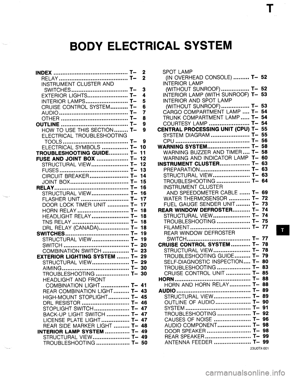
BODY ELECTRICAL SYSTEM
INDEX .......................................... T- 2
RELAY ....................................... T- 2
INSTRUMENT CLUSTER AND
SWITCHES ................................ T- 3
EXTERIOR LIGHTS.. ..................... T- 4
INTERIOR LAMPS.. ...................... T- 5
CRUISE CONTROL SYSTEM.. ........ T- 6
AUDIO ....................................... T- 7
OTHER ...................................... T- 8
OUTLINE ...................................... T- 9
HOW TO USE THIS SECTION.. ...... T- 9
ELECTRICAL TROUBLESHOOTING
TOOLS .....................................
ELECTRICAL SYMBOLS - ............... T- 1x
TROUBLESHOOTING GUIDE.. .........
T- 11
FUSE AND JOINT BOX ..................
T- 12
STRUCTURAL VIEW.. ...................
T- 12
FUSES ....................................... T- 13
CIRCUIT BREAKER.. ....................
T- 14
JOINT BOX ................................. T- 15
RELAY .......................................... T- 16
STRUCTURAL VIEW.. ...................
T- 16
.-
FLASHER UNIT ........................... T- 17
DOOR LOCK TIMER UNIT ............
T- 17
HORN RELAY ............................. T- 18
HEADLIGHT RELAY.. ................... T- 18
TNS RELAY ................................ T- 18
DRL RELAY (CANADA). ................ T- 18
SWITCHES .................................... T- 19
STRUCTURAL VIEW.. ................... T- 19
SWITCH ..................................... T- 20
COMBINATION SWITCH ...............
T- 23
EXTERIOR LIGHTING SYSTEM ....... T- 29
STRUCTURAL VIEW.. ...................
T- 29
AIMING ...................................... T- 30
TROUBLESHOOTING.. .................
T- 30
HEADLIGHT AND FRONT
COMBINATION LIGHT.. ..............
T- 41
REAR COMBINATION LIGHT.. ....... T- 43
HIGH-MOUNT STOPLIGHT.. .......... T- 45
DRL RESISTOR ........................... T- 46
STOPLIGHT SWITCH.. .................. T- 47
BACK-UP LIGHT SWITCH ............. T- 47
LICENSE PLATE LIGHT.. ..............
T- 47
REAR SIDE MARKER LIGHT ......... T- 48
INTERIOR LAMP SYSTEM ..............
T- 49
STRUCTURAL VIEW.. ...................
T- 49
TROUBLESHOOTING ...................
T- 50 SPOT LAMP
(IN OVERHEAD CONSOLE) ......... T- 52
INTERIOR LAMP
(WITHOUT SUNROOF). ............... T- 52
INTERIOR LAMP (WITH SUNROOF) T- 53
INTERIOR AND SPOT LAMP
(WITHOUT SUNROOF). ............... T- 53
CARGO COMPARTMENT LAMP.. .. T- 54
TRUNK COMPARTMENT LAMP.. ... T- 54
COURTESY LAMP ....................... T- 54
CENTRAL PROCESSING UNIT (CPU) T- 55
SYSTEM DIAGRAM ...................... T- 55
CPU .......................................... T- 56
WARNING SYSTEM.. ...................... T- 58
WARNING BUZZER AND TIMER .... T- 58
WARNING AND INDICATOR LAMP T- 60
INSTRUMENT CLUSTER.. ............... T- 63
PREPARATION ............................ T- 63
STRUCTURAL VIEW ..................... T- 63
TROUBLESHOOTING ................... T- 64
INSTRUMENT CLUSTER
AND SPEEDOMETER CABLE.. .... T- 89
WATER THERMOSENSOR ............ T- 72
FUEL GAUGE SENDER UNIT.. ...... T- 73
REAR WINDOW DEFROSTER.. ........ T- 74
STRUCTURAL VIEW.. ................... T- 74
TROUBLESHOOTING ................... T- 75
FILAMENT .................................. T- 77
REAR WINDOW DEFROSTER
SWITCH .................................... T- 77
CRUISE CONTROL SYSTEM.. ......... T- 78
STRUCTURAL VIEW.. ................... T- 78
TROUBLESHOOTING GUIDE.. ....... T- 79
SELF-DIAGNOSTIC INSPECTION .... T- 80
TROUBLESHOOTING ................... T- 83
CRUISE CONTROL UNIT .............. T- 85
HORN ........................................... T- 88
HORN AND HORN RELAY.. .......... T- 88
AUDIO .......................................... T- 89
STRUCTURAL VIEW.. ................... T- 89
OUTLINE OF AUDIO.. .................. T- 90
SYSTEM ..................................... T- 91
TROUBLESHOOTING ................... T- 92
CAUSES OF NOISE ..................... T- 96
AUDIO COMPONENT.. ................. T- 98
DOOR SPEAKER .........................
REARSPEAKER .......................... ;-
- !3;
ANTENNA FEEDER ..................... T- 99
23UOTX-001
Page 864 of 1164

T INDEX
OTHER
1, Joint box (including CPU)
Removal / Installation . . . . . . . . . . . . . . . . . . page T-l 5
Inspection . . . . . . . . . . . . . . . . . . . . . . . . . . . . . . . . . . . page T-58
2. Circuit breaker
Note . . . . . . . . . . . . . . . . . . . . . . . . . . . . . . . . . . . . . . . . . . . .
page T-14
3. Horn
Removal I Installation . . . . . . . . . . . . . . . . . . page T-88
23UOTX-OOf
4. Main fuse
Removal I Installation . . . . . . . . . . . . . . . . . . page T-14
5. Rear window defroster (Filament)
Troubleshooting ,..........,,...,........,
page T-75
Inspection . . . . . . . . . . . . . . . . . . . . . . . . . . . . . . . . . . . page T-77
Repairing . . . . . . . . . . . . . . . . . . . . . . . . . . . . . . . . . . . .
page T-77
T-8
Page 866 of 1164

T
ELECTRICAL SYMBOLS
Switches and Relays OUTLINE
There is an NC (normally closed) and NO (normally open) indication for switches and relays which shows
when no change of operation conditions has occurred.
Relay Switch
NO type relay NC type relay NO switch NC switch
Not in operation
(No power supply) +E+ #Fig -o-- -da--
ax ax
STOP
FLOW STOP FLOW
In operation
(Power supply) * !jiij! kiig 6 dLe
cw r”X
FLOW STOP FLOW STOP
Other Electrical Symbols
BATTERY
THERMISTER DIODE CONDENSER
Q
M
MOTOR I
T-10
l-
BODY GROUND
COIL, SOLENOID i
0 8 HOLDER BOX
FUSE
RESISTOR
1
T
FUSIBLE LINK
1 i 1
VARIABLE RESISTOR
LIGHT
HEATER
69G15X-O(
Page 868 of 1164

T FUSE AND JOINT BOX
FUSE AND JOINT BOX
STRUCTURAL VIEW
13UO-wOl(
1. Main fuse
3. Joint box
Removal I Installation
.................. page T-14 Removal I Installation
.................. page T-l 5
2. Fuse
Inspection ...................................
page T-58
Removal / Installation
.................. page T-l 4
T-12
Page 869 of 1164

FUSE AND JOINT BOX
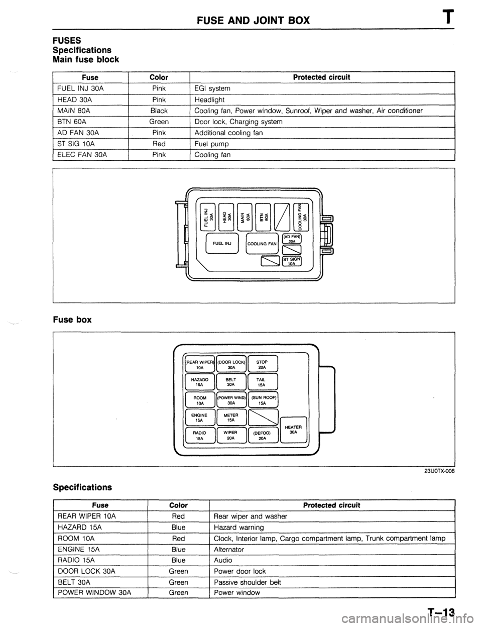
FUSES
Specifications
Main fuse block
Fuse Color
FUEL INJ 30A Pink
HEAD 30A Pink
MAIN 80A Black
BTN 60A Green
AD FAN 30A Pink
ST SIG 10A Red
ELEC FAN 30A Pink Protected circuit
EGI system
Headlight
Cooling fan, Power window, Sunroof, Wiper and washer, Air conditioner
Door lock, Charging system
Additional cooling fan
Fuel pump
Cooling fan
Fuse box
23UOTX-001
Specifications
Fuse
REAR WIPER 10A
HAZARD 15A
ROOM IOA
ENGINE 15A
RADIO 15A
DOOR LOCK 30A
BELT 30A
POWER WINDOW 30A Color
Red
Blue
Red
Blue
Blue
Green
Green
Green Protected circuit
Rear wiper and washer
Hazard warning
Clock, interior lamp, Cargo compartment lamp, Trunk compartment lamp
Alternator
Audio
Power door lock
Passive shoulder belt
Power window
1
T-13