fuse MAZDA PROTEGE 1992 Owner's Manual
[x] Cancel search | Manufacturer: MAZDA, Model Year: 1992, Model line: PROTEGE, Model: MAZDA PROTEGE 1992Pages: 1164, PDF Size: 81.9 MB
Page 870 of 1164

T FUSE AND JOINT BOX
Specifications (Cont’d)
Fuse Color
METER 15A Blue
WIPER 20A Yellow
STOP 20A Yellow
TAIL 15A
Blue
SUNROOF 15A Blue
DEFOG 20A Yellow
HEATER 30A Light green Protected circuit Instrument panel (gauges and warning lamps), Back-up light, Turn signal,
Cruise control system
Windshield wiper and washer
Stoplight, Horn
Taillight, Side marker light, Parking light, Illumination light, License plate light
Sunroof
Rear window defroster
Blower motor
13UOTX-067
L
r 03UOTX-01
1 BL
PULLER
t
L 03UOTX-01
CIRCUIT
BREAKER
RESET BUTTON
03UOTX.01
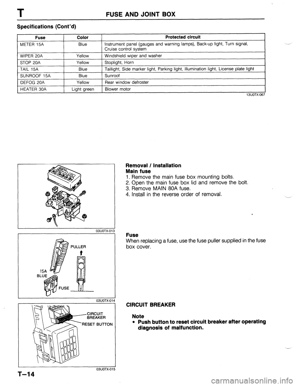
Removal / Installation
Main fuse
1. Remove the main fuse box mounting bolts.
2. Open the main fuse box lid and remove the bolt.
3. Remove MAIN 80A fuse.
4. Install in the reverse order of removal.
Fuse
When replacing a fuse, use the fuse puller supplied in the fuse
box cover.
CIRCUIT BREAKER
Note
l Push button to reset circuit breaker after operating
dlagnosls of malfunction.
5
T-14
Page 871 of 1164

FUSE AND JOINT BOX T
JOINT BOX
Removal / Installation
1. Remove in the order shown in the figure.
2. install in the reverse order of removal.
1. Scuff plate
2. Seaming welt
3. Front side trim 2. J$n; box (including CPU)
Inspection *.,,...,....................*...... page T-57
T-15
Page 888 of 1164

I
EXTERIOR LIGHTING SYSTEM
Headlights do not operate (Low and/or High)
(Without cruise)
I
Turn ON light switch (second position)
I
Check head 30A main fuse Short circuit
0
Confirm battery voltage on R w Repair harness (Main fuse - Combination switch) L
I
0 OK
Confirm battery voltage on R wire (when Low) and/or
R/W wire (when High) of the combination switch Replace the combination switch
Confirm battery voltage on R wire (when Low) and/or
R/W wire (when High) of the headlight Repair harness (Combination switch - Headlight)
I
0
Confirm continuity on B wire of the headlight
Repair harness (Headlight - Body ground)
Burnt out bulb
23UOTX-017 Headlights do not operate (Low and/or High)
I
(With cruise)
I
Turn ON light switch (second position)
Short circuit
0 OK
Confirm battery voltage on W/R wire of the combination switch
I
8) C OK Repair harness (Main fuse - Headlight relay)
I
Replace the headlight relay
1
Repair harness (Headlight relay - Combination switch)
Confirm battery voltage on R wire (when Low) and/or
R/W wire (when High) of combination switch connector Replace the combination switch
1
Q 1 OK
Disconnect headlight connector. Confirm battery voltage
on R wire (when Low) and/or on RIW wire (when High)
of connector
,o OK
Repair harness (Combination switch - Headlight)
1
I
Confirm continuity on B wire of the headlight connector
to ground Repair harness (Headlight - Body ground)
I
T-32
OK _ Replace the bulbs
23UOTX-018
Page 889 of 1164

EXTERIOR LIGHTING SYSTEM T
Headlights either do not operate or are dim Low-High beam or passing flasher does not
J operate
Burnt out bulb or poor grounding J
03UOTX-049 Defective combination switch
03UOTX-050
(Canada) Daytime running lights (DRL) do not operate
Confirm that headlights operate with the light switch ON
(second position) OK
Turn OFF the light switch and turn ON the ignition
switch when parking level pulling
I
Check head 30A main fuse OK
Check DRL resistor OK Repair DRL resistor 10A fuse
Confirm battery voltage on R and L/G wire of the DRL NG
relay Repair harness (Fuse - DRL relay)
I
I
Check the DRL relay
Repair DRL relay
1 OK
Confirm battery voltage on (BRNV) wire of the DRL con-
trol unit NG
Repair harness (DRL relay - DRL control unit) OK
Confirm battery voltage on (L/G) wire of the DRL control NG
unit Repair harness (Rear wiper fuse - DRL control unit) OK
Confirm continuity of (G/R) wire of the DRL control unit x Repair harness (DRL control unit - Parking brake
to ground switch) or check the parking brake switch 1 OK
Confirm continuity on (B) wire of the DRL control unit to
NG
ground Repair harness (DRL control unit ground) OK
-1 NG
Confirm approx. 8V on the DRL resistor Repair harness (DRL control unit - DRL headlight)
I
Confirm battery voltage on (
Confirm approx. 8V on (R/W) wire of the DRL resistor Repair harness (DRL resistor - DRL relay)
Repair harness (DRL control unit - DRL resistor)
23UOTX-019
T-33
Page 891 of 1164

EXTERIOR LIGHTING SYSTEM
Turn Signal lights do not operate
Check meter 15A fuse A an
I
0 OK
Confirm battery voltage on BI Repair harness (Fuse - Turn switch) OK
1 ~,-
Check the turn signal switch NG
(Refer to page T-27 or T-28) Replace the turn switch
1 OK
Turn ignition switch to ON. Turn the signal switch to
RIGHT or LEFT
Confirm battery voltage on G or Y wire of the flasher
unit Repair harness (Turn switch - Flasher unit)
6) OK
Confirm battery voltage on B Repair harness (Fuse - Flasher unit)
1
1 OK
Check the flasher unit (Refe Replace the flasher unit
I
(B OK
Confirm battery voltage on G/W (G/B) wire of the turn
signal light NG _
Repair harness (Flasher unit - Turn signal light) @ OK
Confirm continuity on B wire of the turn signal light to
ground OK
Replace the bulb NG
Repair harness (Turn signal light - Body ground)
23UOTX-020
T-35
Page 894 of 1164

I
EXTERIOR LIGHTING SYSTEM
TNS system (side marker, license, tail, illumination
light) does not operate
I
Turn ON light switch
I
Check tail 15A fuse
I OK
Confirm battery voltage on W/B wire of TNS relay
connector Repair harness (Main fuse - TNS relay)
I OK
Check TNS relay (Refer to page T-42) Replace the TNS relay OK
Confirm battery voltage on L/G wire of the combination NG
switch Repair harness (TNS relay - Combination switch)
I OK
Confirm battery voltage on RIB wire of front and rear
side marker, license, tail, and illumination light
connectors Repair harness (TNS relay - Lights)
I OK
Confirm continuity on B wire of above connectors to
ground NO
- Repair harness (Lights - Body ground)
Replace the bulbs
I
23UOTX-022
T-38
Page 896 of 1164

I
EXTERIOR LIGHTING SYSTEM
Both stoplights do not operate when brake pedal is
depressed
i
Check stop 20A fuse
I Short circuit
Confirm battery voltage on G/W wire of the stoplight
switch
I Repair harness (Fuse - Stoplight switch) OK
Check the voltage with the brake pedal depressed
I
BD
c
Confirm battery voltage on G Replace the stoplight switch
8) OK
Confirm battery voltage on G Repair harness (Stoplight switch - Stoplight)
(B
Confirm continuity on B wir Repair harness (Stoplight - Body ground)
I I I
I
Replace the bulb
I
23UOTX-023 One stoplight does not come on
Burnt out bulb or faulty grounding
03UOTX-058
T-40
Page 902 of 1164

T EXTERIOR LIGHTING SYSTEM
Hatchback
03UOTX-07:
1. Cover
2. Screw
3. Lens
03UOTX-1
4. Bulb
Visual inspection
DRL RESISTOR
Removal / Installation
1. Remove the nut and the bolt.
2. Remove the DRL resistor bracket.
3. Install in the reverse order of removal.
Inspection
Confirm that fuse is not burnt out.
T-46
Page 907 of 1164

INTERIOR LAMP SYSTEM T
IG key illumination does not operate
Check room IOA fuse NG
- Short circuit
0 OK
Confirm battery voltage on V Defective harness (Fuse - Joint box), or bulb
0 OK
Confirm continuity on B wire of the joint box (CPU) to
ground Repair harness (Joint box - Body ground)
OK
When any door is opened, confirm that interior lamp
comes on
OK NG
~ Defective harness (Joint box - Door switch), or door
switch
Confirm continuity between N terminal of JB-09 connec- _ NG
-
tor and B terminal of JB-03 connector Repair harness (JB-09 - JB-03)
I OK
Replace CPU
23UOTX-029
Inspection
Door switch (Front sides with passive belt)
Confirm continuity between the R/W wire and the B wire of
the door switch connector (in passive motor connector).
Condition Continuity
Push X
Not push 0
0: Indicates continuity X: No continuity
03UOTX-181 Door switch (Others)
Confirm for continuity between the terminals of the door switch.
Condition Continuity
Push X
Not push 0
0: Indicates continuity X: No continuity
1 I OSJOTX-082
T-51
Page 917 of 1164

WARNING SYSTEM T
13UOTX-07
63U15X-05
, I//
‘nF -
-
-
FUEL
13UOTX.08C
- CHARGE
13UOTX-08
13UOTX-08
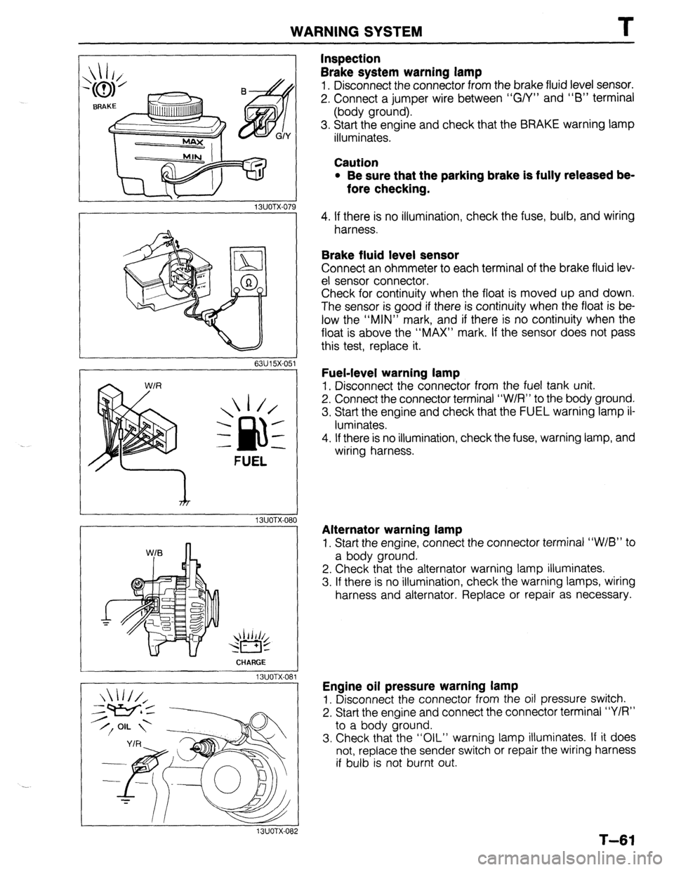
Inspection
Brake system warning lamp
1. Disconnect the connector from the brake fluid level sensor.
2. Connect a jumper wire between “G/Y” and “6” terminal
(body ground).
3. Start the engine and check that the BRAKE warning lamp
illuminates.
Caution
l Be sure that the parking brake is fully released be-
fore checking.
4. If there is no illumination, check the fuse, bulb, and wiring
harness.
Brake fluid level sensor
Connect an ohmmeter to each terminal of the brake fluid lev-
el sensor connector.
Check for continuity when the float is moved up and down.
The sensor is good if there is continuity when the float is be-
low the “MIN” mark, and if there is no continuity when the
float is above the “MAX” mark. If the sensor does not pass
this test, replace it.
Fuel-level warning lamp
1. Disconnect the connector from the fuel tank unit.
2. Connect the connector terminal “W/R” to the body ground.
3. Start the engine and check that the FUEL warning lamp il-
luminates.
4. If there is no illumination, check the fuse, warning lamp, and
wiring harness.
Alternator warning lamp
1. Start the engine, connect the connector terminal “W/B” to
a body ground.
2. Check that the alternator warning lamp illuminates.
3. If there is no illumination, check the warning lamps, wiring
harness and alternator. Replace or repair as necessary.
Engine oil pressure warning lamp
1. Disconnect the connector from the oil pressure switch.
2. Start the engine and connect the connector terminal “Y/R”
to a body ground.
3. Check that the “OIL” warning lamp illuminates. If it does
not, replace the sender switch or repair the wiring harness
if bulb is not burnt out.
T-61