fuse MAZDA PROTEGE 1992 Owner's Guide
[x] Cancel search | Manufacturer: MAZDA, Model Year: 1992, Model line: PROTEGE, Model: MAZDA PROTEGE 1992Pages: 1164, PDF Size: 81.9 MB
Page 918 of 1164
T
I WARNING SYSTEM
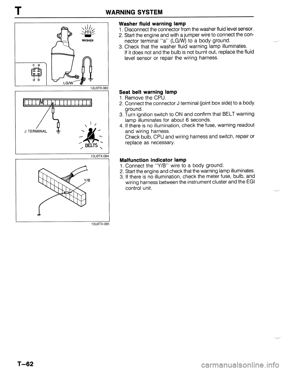
Washer fluid warning lamp
1. Disconnect the connector from the washer fluid level sensor.
2. Start the engine and with a jumper wire to connect the con-
nector terminal “a” (LGIW) to a body ground.
3. Check that the washer fluid warning lamp illuminates.
If it does not and the bulb is not burnt out, replace the fluid
level sensor or repair the wiring harness.
13UOTX-08
_-
1 /
J TERMINAL -
13UOTX-08
13UOTX-08
Seat belt warning lamp
1, Remove the CPU.
2. Connect the connector J terminal (joint box side) to a body
ground.
3. Turn ignition switch to ON and confirm that BELT warning
lamp illuminates for about 6 seconds.
4. If there is no illumination, check the fuse, warning readout
and wiring harness.
Check bulb, CPU and wiring harness and switch, repair or
replace as necessary.
Malfunction indicator lamp
1, Connect the “Y/B” wire to a body ground.
2. Start the engine and check that the warning lamp illuminates.
3. If there is no illumination, check the meter fuse, bulb, and
wiring harness between the instrument cluster and the EGI
control unit.
T-62
Page 932 of 1164

REAR WINDOW DEFROSTER
Defroster does not operate
1
Check defog 20A fuse Short circuit (Broken wire)
0 OK
Turn Ign switch to ON
Confirm battery voltage on B/W wire of rear window
defroster switch Repair harness (Fuse - Rear window defroster switch)
0 1 OK
Confirm battery voltage on B/L wire of rear window
defroster switch with the switch ON
I NG
) Check rear window defroster switch
(Refer to page T-77)
0 OK
With the switch ON, confirm battery voltage on B/L wire NG ) Repair harness (Rear window defroster switch -
of the defroster filament Filament)
I
0 1 OK -1 NG
Confirm OV on B wire of the defroster filament - Faulty grounding
Check filament (Refer to page T-77)
23UOTX-047
T-76
Page 937 of 1164

CRUISE CONTROL SYSTEM T
L 23UOTX-05
Condition Code Numbers
Self-diagnosis of malfunction
The test light will flash if a malfunction is present.
Inspection Procedure
Self-diagnosis of malfunction
1. Locate the cruise control connector.
2. Connect a 1.4W test light between terminals f and d, with
connector attached to control unit.
Note
l There is no wire in terminal d of the connector. Push
the test light through the connector and touch the
corresponding pin on the control unit.
3. Turn the ignition switch to ON.
4. Turn the cruise control on by pressing the MAIN switch. (The
MAIN indicator lamp will come ON.)
5. Press and hold the RESUMElACCEL switch for more than
three second.
6. The test light will illuminate for 3 seconds and go out for
2 seconds.
7. The self-diagnostic system is activated and the test light will
flash if a problem is present.
8. Make note of the condition code number(s).
(Refer to the chart at the bottom of the page).
9. After retrieving the code(s), drive the vehicle at more than
16 km/h (lOmph), or press the MAIN switch to deactivate
self-diagnosis. (The MAIN indicator lamp will go OFF.)
Note
l The cruise control system will not operate when in
the self-diagnosis mode.
Pattern of output signal
(Test light)
ON
OFF ON
GFF
,“r,- ON
OFF Note
23UOTX-05
l
If there is more than one malfunction, the code numbers will be indicated in numerical order.
T-81 Code
No.
01
05 Possible Cause Action
Defective wiring (Actuator-Cruise control
unit, Stoplight switch-Cruise control unit)
Defective actuator
Defective stoplight switch (For cruise)
STOP fuse blown
Defective wiring (Fuse - Cruise control
unit)
Both stoplight switches (for vehicle and
cruise) are ON simultaneously
Defective SET/COAST. or RESUME/ Inspect cruise control switch
ACCEL switch (Refer to page T-21)
Defective cruise control unit Repair harness
Inspect actuator
(Refer to page T-87)
Inspect stoplight switch
(Refer to page T-87)
Replace fuse
Repair harness
Inspect stoplight switches
(Refer to pages T-47 and
T-87)
Go to troubleshooting
(Refer to page T-83)
Page 949 of 1164
AUDIO
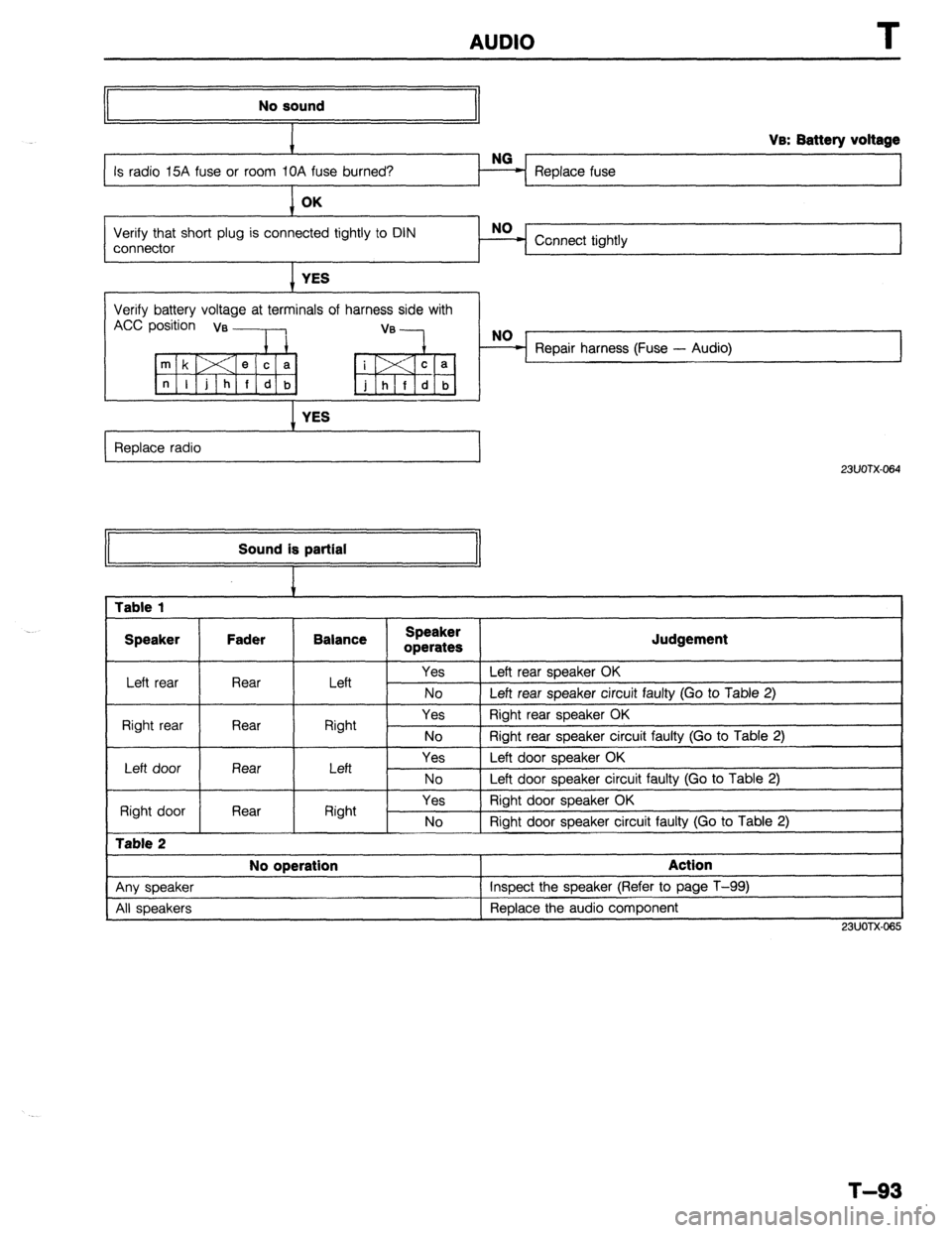
No sound
Replace fuse Va: Battery voltage
Verify that short plug is connected tightly to DIN
connector Connect tightly
I YES
Verify battery voltage at terminals of harness side with
Accp;;;ia, ,:---lb, “‘-k,
I YES
Replace radio
I
23UOTX-064 Sound is partial
1 Table 1
I Speaker Fader Balance
I Speaker
operates
I Judgement
Left rear Rear I Left Yes 1 Left rear speaker OK
No 1 Left rear soeaker circuit faulty (Go to Table 2)
Right rear Rear
I Right Yes Right rear speaker OK
No 1 Riaht rear sneaker circuit fauftv (Go to Table 2)
I
Left door
Right door
Table 2
Rear
Rear Left
Right Yes
No
Yes
No Left door speaker OK
Left door speaker circuit faulty (Go to Table 2)
Right door speaker OK
Right door speaker circuit faulty (Go to Table 2)
I No operation
I Action
I
1 Anv sneaker 1 Insoect the speaker (Refer to page T-99)
I
All speakers Replace the audio component
I
23UOTX.065
T-93
Page 962 of 1164
U TROUBLESHOOTING GUIDE
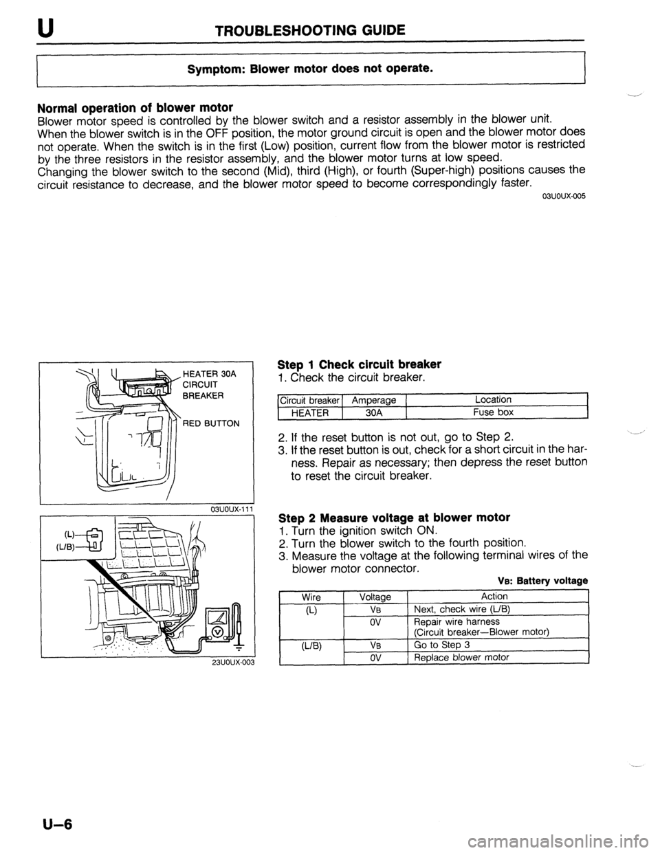
Symptom: Blower motor does not operate.
Normal operation of blower motor
Blower motor speed is controlled by the blower switch and a resistor assembly in the blower unit.
When the blower switch is in the OFF position, the motor ground circuit is open and the blower motor does
not operate. When the switch is in the first (Low) position, current flow from the blower motor is restricted
by the three resistors in the resistor assembly, and the blower motor turns at low speed.
Changing the blower switch to the second (Mid), third (High), or fourth (Super-high) positions causes the
circuit resistance to decrease, and the blower motor speed to become correspondingly faster.
03uoux-005
. HEATER 30A
CIRCUIT
BREAKER
RED BUTTON
23UOUX-01
Step 1 Check circuit breaker
1. Check the circuit breaker.
ircuit breaker] Amperage ( Location
HEATER 1 30A Fuse box
2. If the reset button is not out, go to Step 2.
3. If the reset button is out, check for a short circuit in the har-
ness. Repair as necessary; then depress the reset button
to reset the circuit breaker.
Step 2 Measure voltage at blower motor
1. Turn the ignition switch ON.
2. Turn the blower switch to the fourth position.
3. Measure the voltage at the following terminal wires of the
blower motor connector.
VB: Battery voltage
Wire
Voltage Action
a-) VB Next, check wire (L/B)
ov ReDair wire harness
(Ciicuit breaker-Blower motor)
U-W VB Go to Step 3
ov Replace blower motor
U-6
Page 968 of 1164
TROUBLESHOOTING GUIDE
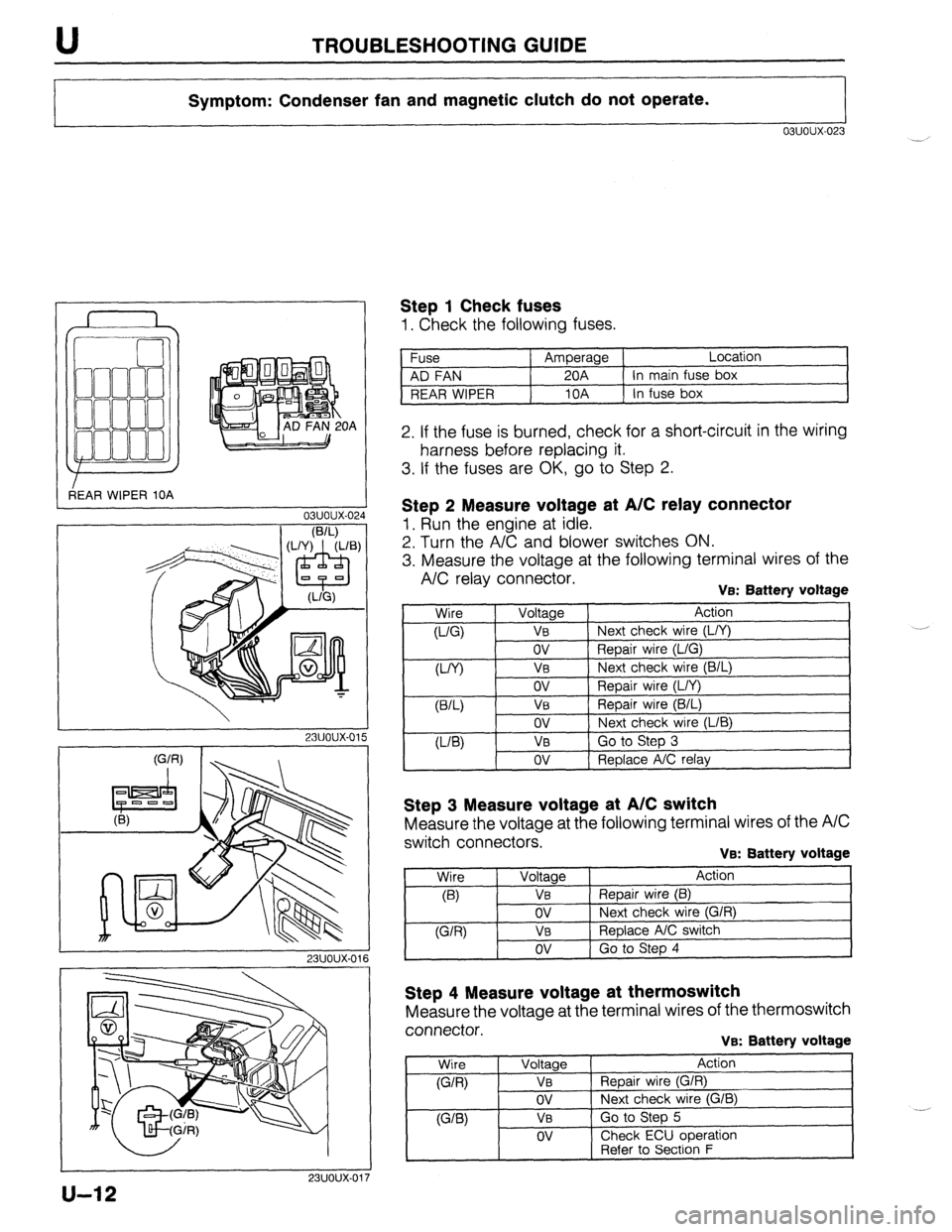
Symptom: Condenser fan and magnetic clutch do not operate.
03uoux-023
r
3EAR WIPER 10A OA
L
03uoux-02.
I
1 Step 1 Check fuses
1. Check the following fuses.
Fuse Amperage Location
AD FAN 20A In main fuse box
REAR WIPER 10A In fuse box
2. If the fuse is burned, check for a short-circuit in the wiring
harness before replacing it.
3. If the fuses are OK, go to Step 2.
I
23uoux-011
Step 2 Measure voltage at A/C relay connector
1. Run the engine at idle.
2. Turn the A/C and blower switches ON.
3. Measure the voltage at the following terminal wires of the
A/C relay connector. VEX Battery voltage
,
Wire
0-Q
W) Voltage Action
VB Next check wire (L/Y)
ov Repair wire (L/G)
V0 Next check wire (B/L)
ov
VB
ov
VB
ov Repair wire (L/Y)
Repair wire (B/L)
Next check wire (LIB)
Go to Step 3
Replace A/C relay
Step 3 Measure voltage at A/C switch
Measure the voltage at the following terminal wires of the A/C
switch connectors.
VB: Battery voltage
Step 4 Measure voltage at thermoswitch
Measure the voltage at the terminal wires of the thermoswitch
connector.
VB: Battery voltage
Wire
(G/R)
WB)
Voltage
VB
ov
VB
OV
Action
Repair wire (G/R)
Next check wire (G/B)
Go to Step 5
Check ECU ooeration
1 -. [ Refer to Secti6n F
u-12
Page 1050 of 1164

PARTS INDEX
I
CRANKSHAFT.. ....................................
I31 -64
CYLINDER BLOCK .............................. 61-60
CYLINDER HEAD..
............................... 81-54
CYLINDER HEAD GASKET .................
Bl-16
DRIVE BELT(S). ...................................... 81-5
FRONT OIL SEAL ................................ 81-23
HLA .............................................. Bl-7,20,60
OIL JET ................................................ 81-61
PISTON.. ...............................................
Bl-62
PISTON PIN..
........................................ 81-62
PISTON RING
....................................... 81-62
REAR
OIL SEAL..
................................. 81-25
TENSIONER, IDLER ............................. Bl-65
TENSIONER
SPRING ...........................
Bl-65
TIMING BELT ..................................
Bl-12,65
TIMING BELT PULLEY ........................
Bl-65
VALVE MECHANISM ........................... Bl-55
ENGINE
(BP DOHC) .................................... B2-2
CAMSHAFT ..........................................
82-58
CAMSHAFT PULLEY ...........................
B2-65
CONNECTING ROD..
........................... 82-63
CRANKSHAFT ......................................
B2-64
CYLINDER BLOCK ..............................
82-60
CYLINDER
HEAD.. ............................... B2-54
CYLINDER HEAD GASKET .................
82-16
DRIVE
BELTS.. .......................................
B2-5
FRONT
OIL SEAL ................................
82-26
H LA ..............................................
OIL JET .......................... B2-7iyL;;
......................
PISTON .................................................
B2-62
PISTON PIN ..........................................
82-62
PISTON RING..
..................................... 82-62
REAR OIL SEAL ................................... B2-28
TENSIONER, IDLER ............................. B2-65
TENSIONER SPRING ........................... B2-65
TIMING
BELT.. ................................
B2-12,65
TIMING BELT PULLEY ........................ 82-65
VALVE MECHANISM ........................... 82-55
ENGINE CONTROL UNIT (ECU) ............... F-149
ENGINE COOLANT
........................................ E-5
ENGINE OIL.. .................................................
D-7
ENGINE OIL FILTER.. .................................... D-8
’ EXHAUST SYSTEM. ...................................
F-136
EXTRACTOR CHAMBER .............................. S-53
F
FAN MOTOR (COOLING FAN). ................... E-14
FAN RELAY (COOLING FAN). ..................... E-18
FLASHER UNIT ............................................
T-17
FLOORMAT ..................................................
S-99
FLYWHEEL ..................................................
H-18
FRONT AXLE .................................................
M-4
FRONT BRAKE ............................................
P-l 8
FRONT BUMPER ......................................... S-39
FRONT DOOR ................................................
S-8
FRONT DOOR LOCK AND OPENER ..........
S-13
PI-2
FRONT FENDER PANEL ............................... S-7
FRONT LOWER ARM .................................. R-16
FRONT SHOCK ABSORBER AND SPRING R-11
FRONT SIDE WINDOW REGULATOR AND
GLASS ........................................................ S-10
FRONT STABILIZER..
................................... R-l 8
FRONT SUSPENSION .................................. R-l 0
FUEL FILLER LID AND OPENER..
.............. S-37
FUEL FILTER .............................................. F-l 24
FUEL GAUGE SENDER UNIT ..................... T-73
FUEL PUMP ............................................... F-125
FUEL TANK
................................................ F-123
FUSE AND JOINT BOX.. .............................. T-12
H
HEADLIGHT AND
FRONT COMBINATION LIGHT..
................ T-41
HEADLIGHT RELAY ..................................... T-l 8
HEADLINER ................................................. S-89
HEATER CONTROL UNIT.. ......................... U-26
HEATER UNIT
.............................................. U-21
HIGH-MOUNT STOPLIGHT
.......................... T-45
HIGH-TENSION LEAD ................................. G-l 7
HOOD ............................................................. S-5
HORN T-88
...........................................................
HORN RELAY
.......................................... T-18,88
.__. ’
I I
IGNITER .......................................................
G-23
IGNITION COIL.. .......................................... G-19
INJECTOR .................................................. F-l 31
INSTRUMENT CLUSTER
AND SPEEDOMETER CABLE
.................... T-69
INTAKE MANIFOLD ................................... F-113
INTERIOR LAMP ..................................... T-52,53
ISC VALVE.. ................................................ F-l 16
J
JOINT SHAFT (FRONT AXLE) .................... M-18
L
LATERAL LINK AND TRAILING LINK.. ....... R-26
LICENSE PLATE LIGHT.. ............................. T-47
i
M
I
---
MAIN RELAY (FUEL INJ. RELAY). ............ F-172
MANUAL STEERING ..................................... N-4
MANUAL TRANSAXLE (F5M-R). .................. Jl-2
Page 1058 of 1164
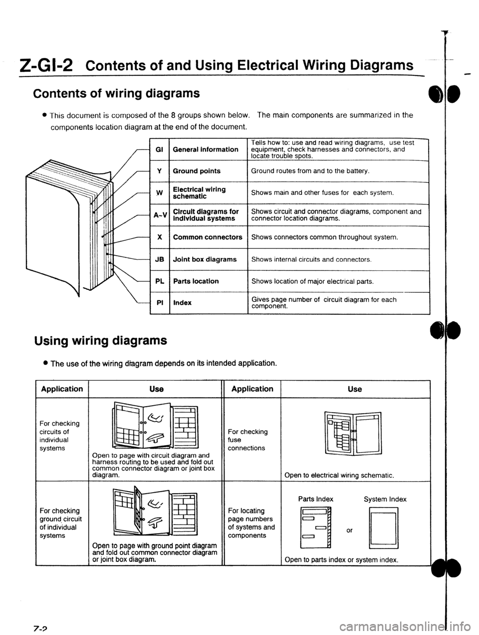
Z-Gl-2 Contents of and Using Electrical Wiring Diagrams
Contents of wiring diagrams
l This document is composed of the 8 groups shown below. The main components are summarized in the
components location diagram at the end of the document.
Tells how to: use and read wiring dragrams, use test
GI General information equipment, check harnesses and connectors, and
locate trouble spots.
Y Ground points Ground routes from and to the battery.
I
w
I Electrical wiring
schematic
I Shows main and other fuses for each system.
lndlvidual systems
I Shows circuit and connector diagrams, component and
connector location diagrams.
1
X
I Common connectors
I Shows connectors common throughout system.
I
JB Joint box diagrams Shows internal circuits and connectors.
PL Parts location Shows location of major electrical parts.
PI Index
I
I
Gives page number of circuit diagram for each
component.
Using wiring diagrams
l The use of the wiring diagram depends on its intended application. Application
For checking
circuits of
individual
systems
For checking
ground circuit
of individual
systems 7-3 Use
II Application
Open to page with circuit diagram and
harness routing to be used and fold out
common connector diagram or joint box
diagram. For checking
fuse
connections Use
Open to electrical wiring schematic.
Open to page with ground point diagram
and fold out common connector diagram
or joint box diagram. For locating
page numbers
of systems and
components Parts Index
H
Open to parts index or system index.
Page 1064 of 1164

Z-Gl-8 Reading Wiring Diagrams
Svmbols I
Symbol Meaning Symbol Meaning
Battery (I, Generates electricity through Resistance l A resistor with a constant value
chemical reaction l Mainly used to protect electrical
l Supplies direct current to circuits components in circuits by maintaining
rated voltage
l Reading resistance values
Ground (1)
l Connecting point to vehicle body or No.1 Cobr band
-A- other ground wire where current flows -No.2 Cobr band
from positive to negative terminal of -No.3 Cobr band
battery No.4 Cobr band
1
l Ground (1) indicates a ground point to Flnt color. Rerkrancs
body through wire harness
Ground (2) l Gound (2) indicates point where
component is grounded directly to body
Remark
oCurrent wilt not flow through a circuit if
ground is faulty
Fuse (1)
(box)
Fuse (2)
l Melts when current flow exceeds that
specified for circuit, stopping current
flow
Precautions
o Do not replace with fuses exceeding
specified capacity
(Cartridge)
vlain fuse/Fusible
l Electrical switching component
a Turns on when voltage is applied to Motor
0 Converts electrical energy into
mechanical energy
Transistor (2)
coiibmr (Cl
l Reading code l Pulls in and expels gases and liquids
Lamp
Number of terminals O:Low- frequency NPN
l Emits light and generates heat when
Cigarette lighter
current flows through filament a Electrical coil that generates heat
Page 1067 of 1164

Troubleshootina Z-GM 1
Precautions when servicing electrical system
l Note the following items when servicing the electrical system.
l Do not alter the wiring or electrical equipment in any way as this may damage the vehicle or cause a fire
due to shorting or overcapacity of a circuit.
l Always disconnect the negative (- ) battery cable first and 0 Replace blown fuses with ones having the same designated
reconnect It last when disconnecting the battery. capacity.
1OA
15A
Zaution
l Be sure that the ignition and other switches are OFF
before disconnecting or connecting the battery
terminals.
Failure to do so may damage the semi-conductor
components. Caution l Replacing a fuse with one of a larger capacity than
designated may damage components or cause an electrical
fire.
l Secure harnesses with a clamp when provided to take Up l Tape areas of the
a Be sure that the harness
any slack. harness that may rub or
is not caught or damaged
bump against sharp
when mounting
edges to protect it from
components.
damage.
Caution
l Clamp all harnesses near vibrating components(e.g.
the engine) to remove any slack and prevent Contact
due to vibration.
l Do not handle roughly or drop electrical components.
l Disconnect heat sensitive
parts (e.g. relays, ECU)
when performing
maintenance where
temperatures may exceed l Make sure that the
connectors are securely
connected when
installed.
80°C (176°F) (i.e.welding).
oid