check engine MAZDA PROTEGE 1992 Owner's Manual
[x] Cancel search | Manufacturer: MAZDA, Model Year: 1992, Model line: PROTEGE, Model: MAZDA PROTEGE 1992Pages: 1164, PDF Size: 81.9 MB
Page 157 of 1164

ON-VEHICLE MAINTENANCE B2
05UOBX-05
BLA-DE 0-dlNG
Steps After Installation
1. Connect the negative battery cable.
2. Start the engine and check as follows:
l Ignition timing. (Refer to page 82-8.) 3. Install the camshaft pulley lock bolts.
4. Hold the camshaft with a wrench.
5. Tighten the camshaft pulley lock bolt.
Tightening torque:
49-61 N-m (5.0-6.2 m-kg, 36-45 ft-lb)
Distributor
1. Apply grease to a new O-ring and the blade.
2. Install the distributor and loosely tighten the installation bolt.
3. Connect the distributor connector.
0311082-039
B2-25
Page 159 of 1164

ON-VEHICLE MAINTENANCE
I 05UOBX-063
Oil seal
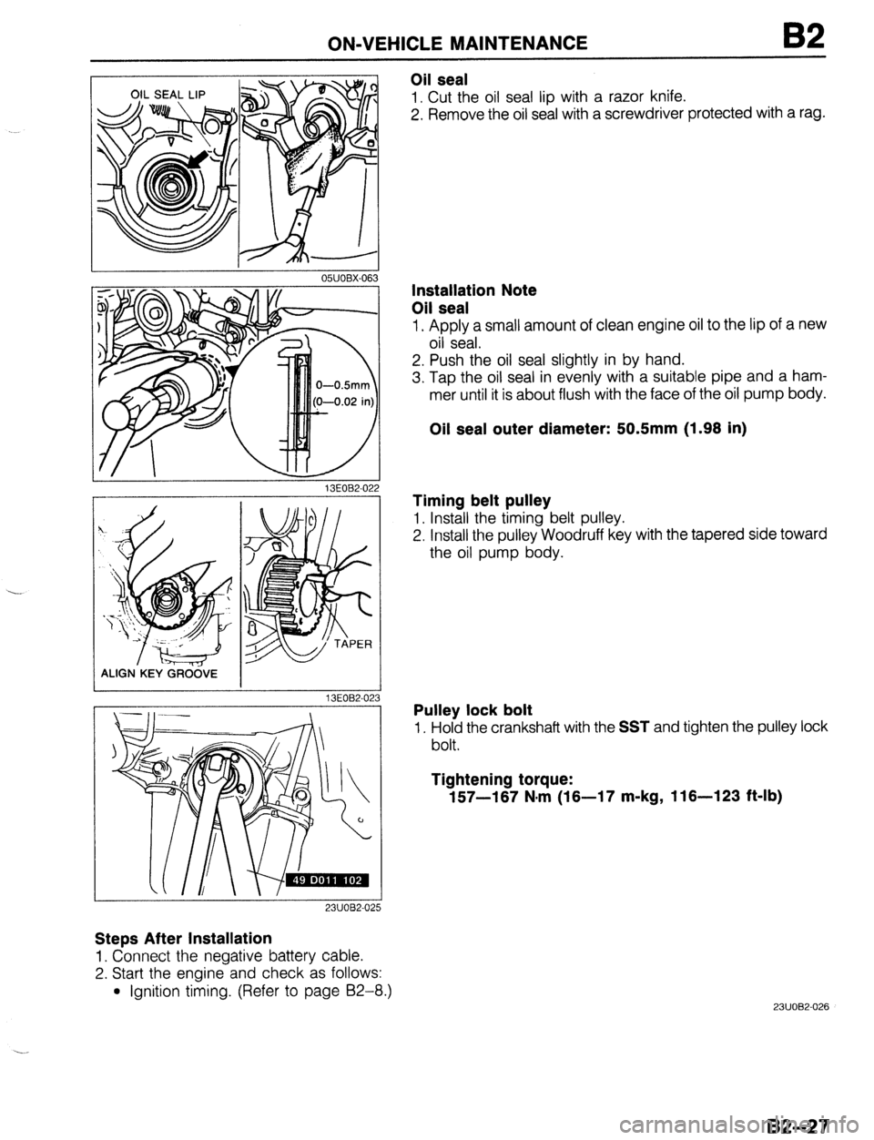
1. Cut the oil seal lip with a razor knife.
2. Remove the oil seal with a screwdriver protected with a rag.
13EOB2-02
ALIGN.KEY GRCi&E
13EOB2-02
23UOB2-025
Steps After Installation
1. Connect the negative battery cable.
2. Start the engine and check as follows:
l Ignition timing. (Refer to page 92-8.)
3
Installation Note
Oil seal
1. Apply a small amount of clean engine oil to the lip of a new
oil seal.
2. Push the oil seal slightly in by hand.
3. Tap the oil seal in evenly with a suitable pipe and a ham-
mer until it is about flush with the face of the oil pump body.
Oil seal outer diameter: 50.5mm (1.98 in)
Timing belt pulley
1. Install the timing belt pulley.
2. Install the pulley Woodruff key with the tapered side toward
the oil pump body.
Pulley lock bolt
1. Hold the crankshaft with the SST and tighten the pulley lock
bolt.
Tightening torque:
157-187 N.m (18-17 m-kg, 116-123 ft-lb)
23UOB2-026
82-27
Page 201 of 1164

ASSEMBLY
2311082-04
05UOBX-17
OSUOBX-17
SPACER TANG
OIL RING
SPACER ENDS
-I
a
5. Tap the piston pin in with the SST until the pin contacts the
clip.
If the pin cannot be installed easily, replace the connecting
rod.
6. Install the second clip into the clip groove in the piston.
7. Check the oscillation torque of the connecting rod. If the
large end does not drop by its own weight, replace the pis-
ton and/or piston pin.
Piston Ring
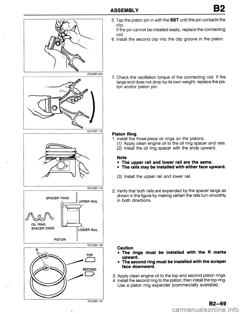
1. Install the three-piece oil rings on the pistons.
(1) Apply clean engine oil to the oil ring spacer and rails.
(2) Install the oil ring spacer with the ends upward.
Note
l The upper rail and lower rail are the same.
l The rails may be installed with either face upward.
(3) Install the upper rail and lower rail.
2. Verify that both rails are expanded by the spacer tangs as
shown in the figure by making certain the rails turn smoothly
in both directions.
Caution
l The rings must be installed with the Fl marks
upward.
l The second ring must be installed with the scraper
face downward.
3. Apply clean engine oil to the top and second piston rings.
4. install the second ring to the piston; then install the top ring.
Use a piston ring expander (commercially available).
132-69
Page 204 of 1164

B2 ASSEMBLY
RUBBER SLEEVE
I
OYJOBX-192
03UOB2-17
03UOB2-09 2 '0
05UOBX-196 Piston and Connecting Rod Assembly
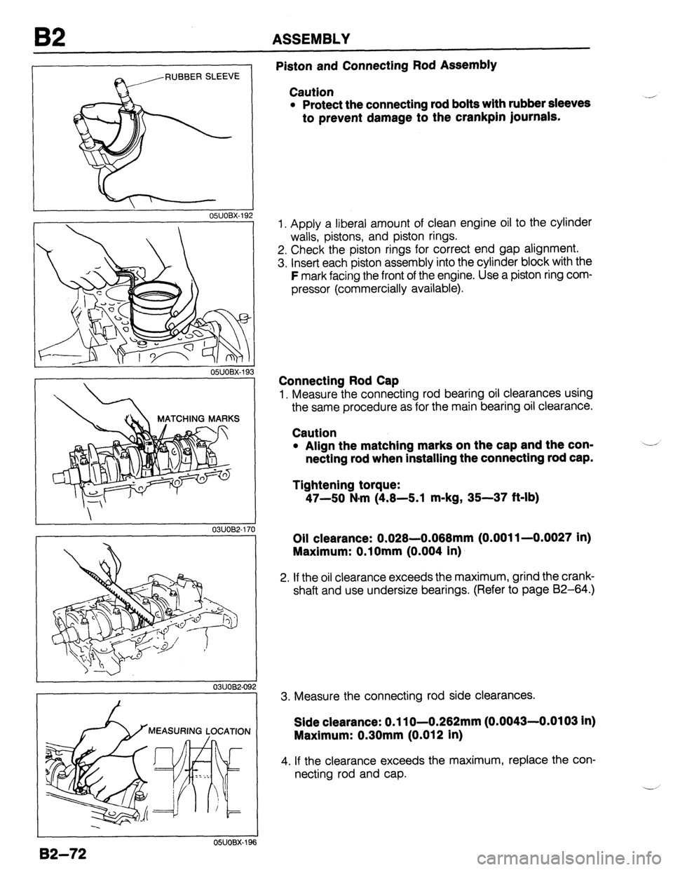
Caution
l Protect the connecting rod bolts with rubber sleeves
to prevent damage to the crankpin journals.
1. Apply a liberal amount of clean engine oil to the cylinder
walls, pistons, and piston rings.
2. Check the piston rings for correct end gap alignment.
3. Insert each piston assembly into the cylinder block with the
F mark facing the front of the engine. Use a piston ring com-
pressor (commercially available).
Connecting Rod Cap
1. Measure the connecting rod bearing oil clearances using
the same procedure as for the main bearing oil clearance.
Caution
l Align the matching marks on the cap and the con-
netting rod when installing the connecting rod cap.
Tightening torque:
47-50 N-m (4.8-5.1 m-kg, 35-37 &lb)
Oil clearance: 0.028.0.088mm (0.001 l-0.0027 in)
Maximum: O.lOmm (0.004 in)
2. If the oil clearance exceeds the maximum, grind the crank-
shaft and use undersize bearings. (Refer to page 82-64.)
3. Measure the connecting rod side clearances.
Side clearance: 0.1 lo-0.282mm (0.0043-0.0103 in)
Maximum: 0.30mm (0.012 in)
4. If the clearance exceeds the maximum, replace the con-
necting rod and cap.
Page 234 of 1164

92 INSTALLATION
RESOiANCE CHAMBER
03UOBZ-154
Accelerator cable
1. Install the accelerator cable.
2. Adjust the cable deflection by turning nut A.
Deflection: 1-3mm (0.04-0.12 in)
Battery duct, battery carrier, and battery
1. Install the battery duct.
Tightening torque:
7.8-l 1 Nlm (80-l 10 cm-kg, 69-96 In-lb)
2. Install the battery carrier.
Tightening torque:
7.8-l 1 N*m (80-l 10 cm-kg, 69-96 in-lb)
3. Install the battery and the battery bracket.
Tightening torque:
2.9-5.9 N*m (30-60 cm-kg, 26-52 in-lb)
Air cleaner assembly
1. Install the air cleaner assembly.
Tightening torque
@: 19-25 N#m (1.9-2.6 m-kg, 14-19 ft-lb)
@: 7.8-l 1 N*m (80-l 10 cm-kg, 69-95 In-lb)
2. Connect the air flow sensor connector.
Resonance chamber
I, Install the resonance chamber.
Tightening torque:
7.8-l 1 N#m (80-l 10 cm-kg, 69-95 In-lb)
Under cover and side cover
1. Install the under cover and side cover.
Steps After Installation
1. If the engine oil was drained, fill with the specified amount and type of engine oil.
(Refer to Section D.)
2. Fill the radiator with the specified amount and type of engine coolant.
(Refer to Section E.)
3. If the transaxle oil was drained, fill with the specified amount and type of transaxle oil.
(Refer to Sections J2, K.)
4. Connect the negative battery cable.
5. Start the engine and check the following:
(1) Engine oil, transaxle oil, and engine coolant leakage.
(2) ignition timing, idle speed. (Refer to page 82-8.)
(3) Operation of emission control system.
6. Perform a road test.
7. Recheck the engine oil and engine coolant levels.
B2-102
2311082.047
Page 240 of 1164

D OIL PRESSURE
OIL PRESSURE
PREPARATION
SST
49 C 187 280
Gauge,
oil pressure
03UODX-03
2
03UODX-007
INSPECTION
1, Remove the intake manifold bracket.
2. Remove the oil pressure switch.
3. Screw the SST into the oil pressure switch installation hole.
4. Warm up the engine to normal operating temperature.
5. Run the engine at 1,000 rpm and 3,000 rpm, and note the
gauge reading.
Oil pressure:
196-294 kPa (2.0-3.0 kg/cm2, 28-43 psi)-1,000 rpm
294-392 kPa (3.0-4.0 kg/cm2, 43-57 psi)-3,000 rpm
6. If the pressure is not as specified, check for the cause and
repair. (Refer to Troubleshooting Guide.)
7. Remove the SST and install the oil pressure switch.
Tightening torque:
12-18 N-m (1.2-l .8 m-kg, 104-156 in-lb)
8. Install the intake manifold bracket.
Tightening torque
@: 37-52 N*m (3.8-5.3 m-kg, 27-38 ft-lb)
0: 19-25 N,m (1.9-2.6 m-kg, 14-19 ft-lb)
Page 241 of 1164

ENGINE OIL, OIL FILTER D
b
I
03UODX-00
ONODX-01
r
03UODX-011
ENGINE OIL
INSPECTION
1. Be sure the vehicle is on level ground.
2. Warm up the engine to normal operating temperature and
stop it.
3. Wait for five minutes.
4. Remove the oil level gauge and check the oil level and con-
dition.
5. Add or replace oil as necessary.
Note
l The distance between the L and F marks on the level
gauge represents 0.8 liter (0.85 US qt, 0.70 Imp qt).
REPLACEMENT
Warning
l Be careful when draining; the oil is hot.
1. Warm up the engine to normal operating temperature and
stop it.
2. Remove the oil filler cap and the oil pan drain plug.
3. Drain the oil into a suitable container.
4. Install a new gasket and the drain plug.
Tightening torque:
29-41 N,m (3.0-4.2 m-kg, 22-30 ft-lb)
5. Refill the engine with the specified type and amount of en-
gine oil.
6. Refit the oil filler cap.
7. Run the engine and check for leaks.
8. Check the oil level and add oil if necessary.
Oil pan capacity
B6 SOHC
BP SOHC and DOHC
liters (US qt, Imp qt)
3.0 (3.2, 2.6)
3.6G.843.2)
w
03UODX-011
D-7
Page 242 of 1164

D OIL FILTER, OIL COOLER
r
\/
OSUODX-0
‘I . 03UODX-01
OIL FILTER
REPLACEMENT
1. Remove the oil filter with a suitable wrench.
2. Use a clean rag to wipe off the mounting surface on the
engine.
3. Apply a small amount of clean engine oil to the rubber seal
of the new filter.
4. Install the oil filter and tighten it by hand until the rubber
seal contacts the base.
5. Tighten the filter 1 and 116 turns with a filter wrench.
6. Start the engine and check for leaks.
7. Check the oil level and add oil if necessary.
Oil filter capacity: 0.17 liter (0.18 US qt, 0.15 Imp qt)
OIL COOLER (BP DOHC)
REMOVAL
1. Drain the engine oil.
2. Remove the oil filter with an oil filter wrench.
3. Disconnect the water hoses.
4. Remove the oil cooler.
INSTALLATION
1. Install the oil cooler.
Tightening torque:
29-39 Nnrn (3.0-4.0 m-kg, 22-29 ft-lb)
2. Install the oil filter. (Refer to page D-8.)
3. Add engine oil to the correct level.
4. After installing the filter, check that there is no oil leakage
while the engine is running.
5. Recheck the oil level using the dipstick.
(Refer to page D-7.)
Page 246 of 1164

OIL PAN
I 03UODX.02
05UOBX.20
1
05UODX-021
56 SOHC
03UODX-02
3P s
03UODX-02!
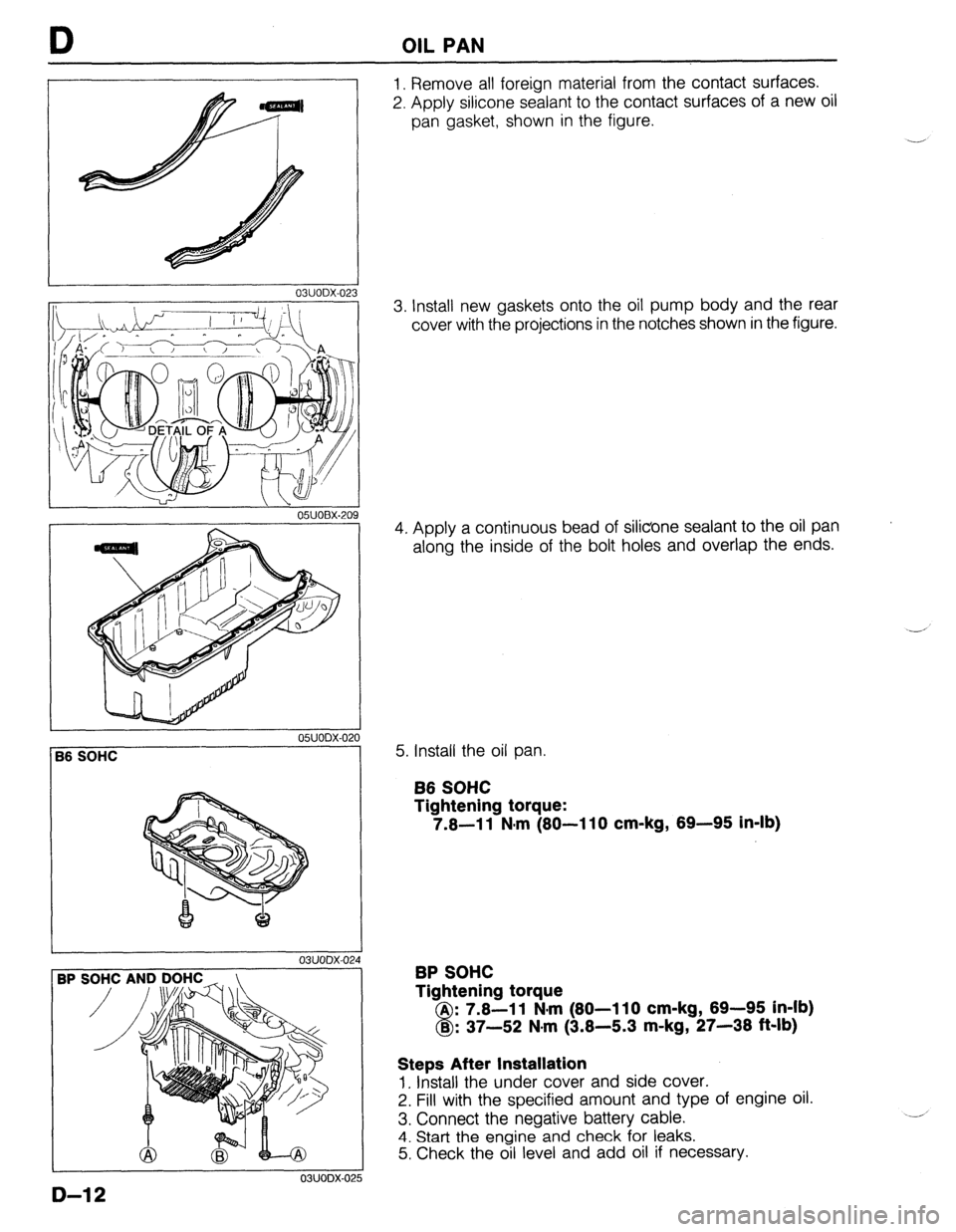
1. Remove all foreign material from the contact surfaces.
2. Apply silicone sealant to the contact surfaces of a new oil
pan gasket, shown in the figure.
3. Install new gaskets onto the oil pump body and the rear
cover with the projections in the notches shown in the figure.
4. Apply a continuous bead of silicone sealant to the oil pan
along the inside of the bolt holes and overlap the ends.
5. Install the oil pan.
B6 SOHC
Tightening torque:
7.6-11 N-m (80-110 cm-kg, 69-95 in-lb)
BP SOHC
Tightening torque
A : 7.8-l 1 N-m (80-l 10 cm-kg, 69-95 in-lb)
8 B : 37-52 N.m (3.8-5.3 m-kg, 27-38 ft-lb)
Steps After Installation
1. Install the under cover and side cover.
2. Fill with the specified amount and type of engine oil.
3. Connect the negative battery cable.
4. Start the engine and check for leaks.
5. Check the oil level and add oil if necessary.
D-12
Page 253 of 1164

ENGINE COOLANT E
ENGINE COOLANT
PREPARATION
SST
49 9200 145
For 49 9200 146
For
inspection of inspection of
cooling system Adapter A cooling system
pressure (Part of pressure
49 9200 145)
05UOEX-00
INSPECTION
Warning
l Never remove the radiator cap while the engine is
hot.
l Wrap a thick cloth around the cap when removing it.
l When removing the radiator cap, loosen it slowly
to the first stop until the pressure in the radiator is
released, and then remove it.
03UOEX~006
Coolant Level (Engine cold)
1. Verify that the coolant level is near the radiator filler neck.
2. Remove the coolant level gauge and check the coolant level.
Coolant Quality
1. Verify that there is no buildup of rust or scale around the
radiator cap or radiator filler neck.
2. Verify that coolant is free of oil. Replace the coolant if
necessary.
Coolant Leakage
1. Connect a radiator tester (commercially available) and the
SST to the radiator filler neck.
2. Apply
103 kPa (1.05 kg/cm2, 15 psi) pressure to the
system.
3. Verify that the pressure is held.
If not, check for coolant leakage.
E-5