engine MAZDA PROTEGE 1992 Owner's Manual
[x] Cancel search | Manufacturer: MAZDA, Model Year: 1992, Model line: PROTEGE, Model: MAZDA PROTEGE 1992Pages: 1164, PDF Size: 81.9 MB
Page 37 of 1164
ENGINE TUNE-UP PROCEDURE Bl
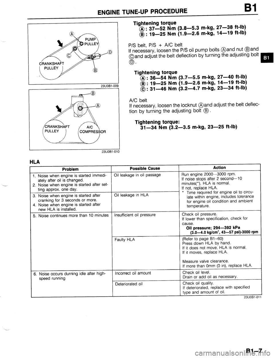
Tightening torque
@ : 37-52 N,m (3.8-5.3 m-kg, 27-38 ft-lb)
@ : 19-25 Nsm (1.9-2.6 m-kg, 14-19 ft-lb)
23UOBl-OC
P/S belt, P/S + A/C belt
If necessary, loosen the P/S oil pump bolts @and nut @and
Oand adjust the belt deflection by turning the adjusting bolt
0.
Tightening torque
@I : 36-54 N.m (3.7-5.5 m-kg, 27-40 ft-lb)
@ : 19-25 N#m (1.9-2.6 m-kg, 14-19 ft-lb)
0: 31-46 N-m (3.2-4.7 m-kg, 23-34 ft-lb)
A/C belt
If necessary, loosen the locknut @and adjust rhe belt deflec-
tion by turning the adjusting bolt @.
Tightening torque:
31-34 N-m (3.2-3.5 m-kg, 23-25 ft-lb)
1
HLA
Problem Possible Cause Action
1. Noise when engine is started immedi- Oil leakage in oil passage Run engine 2000-3000 rpm.
ately after oil is changed. If noise stops after 2 second-10
2. Noise when engine is started after set- minutes(*), HLA is normal.
ting approx. one day. If not, replace HLA.
3. Noise when engine is started after Oil leakage in HLA - * Time required for engine oil to circu-
cranking for 3 seconds or more. late within engine, includes tolerance
4. Noise when engine is started after for engine oil condition and ambient
new HLA is installed. temperature.
5. Noise continues more than 10 minutes Insufficient oil pressure Check oil pressure.
If lower than specification, check for
cause.
Oil pressure; 294-392 kPa
(3.0-4.0 kg/cm*, 43-57 psi)-3000 rpm
(Refer to page 81-60)
Press down HLA by hand.
If it does not move,. HLA is normal.
If it moves, replace HLA.
t
I
Measure valve clearance.
If more than Omm (0 in), replace HLA.
5. Noise occurs durning idle after high-
speed running Incorrect oil amount
Deteriorated oil Check oil level.
Drain or add oil as necessary.
Check oil quality.
If deteriorated, replace with specified
type and amount of oil.
23UOBl-01
Bl-7
Page 38 of 1164
Bl ENGINE TUNE-UP PROCEDURE
13UOBi-036
-i
OWOBX-261
13UOBl-08
LOCK BOLTS
IGNITION TIMING, IDLE SPEED
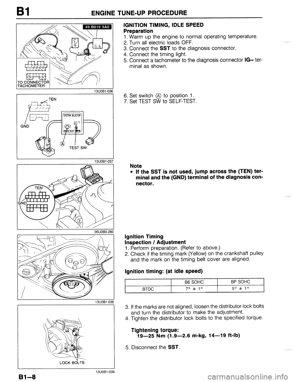
Preparation
1, Warm up the engine to normal operating temperature.
2. Turn all electric loads OFF.
3. Connect the
SST to the diagnosis connector.
4. Connect the timing light.
5. Connect a tachometer to the diagnosis connector
IG- ter-
minal as shown.
6. Set switch @ to position 1.
7. Set TEST SW to SELF-TEST.
Note
l If the SST is not used, jump across the (TEN) ter-
minal and the (GND) terminal of the diagnosis con-
nector.
Ignition Timing
Inspection / Adjustment
1. Perform preparation. (Refer to above.)
2. Check if the timing mark (Yellow) on the crankshaft pulley
and the mark on the timing belt cover are aligned.
Ignition timing: (at idle speed)
B6 SOHC
BTDC 70 f 10 BP SOHC
5O f lo
3. If the marks are not aligned, loosen the distributor lock bolts
and turn the distributor to make the adjustment.
4. Tighten the distributor lock bolts to the specified torque.
Tightening torque:
19-25 N.m (1.9-2.6 m-kg, 14-19 ft-lb)
5. Disconnect the SST.
Bl-8
13UOBl-039
Page 39 of 1164
ENGINE TUNE-UP PROCEDURE Bl
13UOBl-04 0
Idle Speed
1. Perform “Preparation”. (Refer to page Bl-8.)
2. Apply parking brake.
3. Check that the idle speed is within specification.
Idle speed (Neutral or P range): 750 f 50 rpm
Caution
l Check the idle speed without the electric cooling
fan operating.
Note
l When the parking brake is not applied, the idle
speed for ATX model (Canada) is approx. 800 rpm.
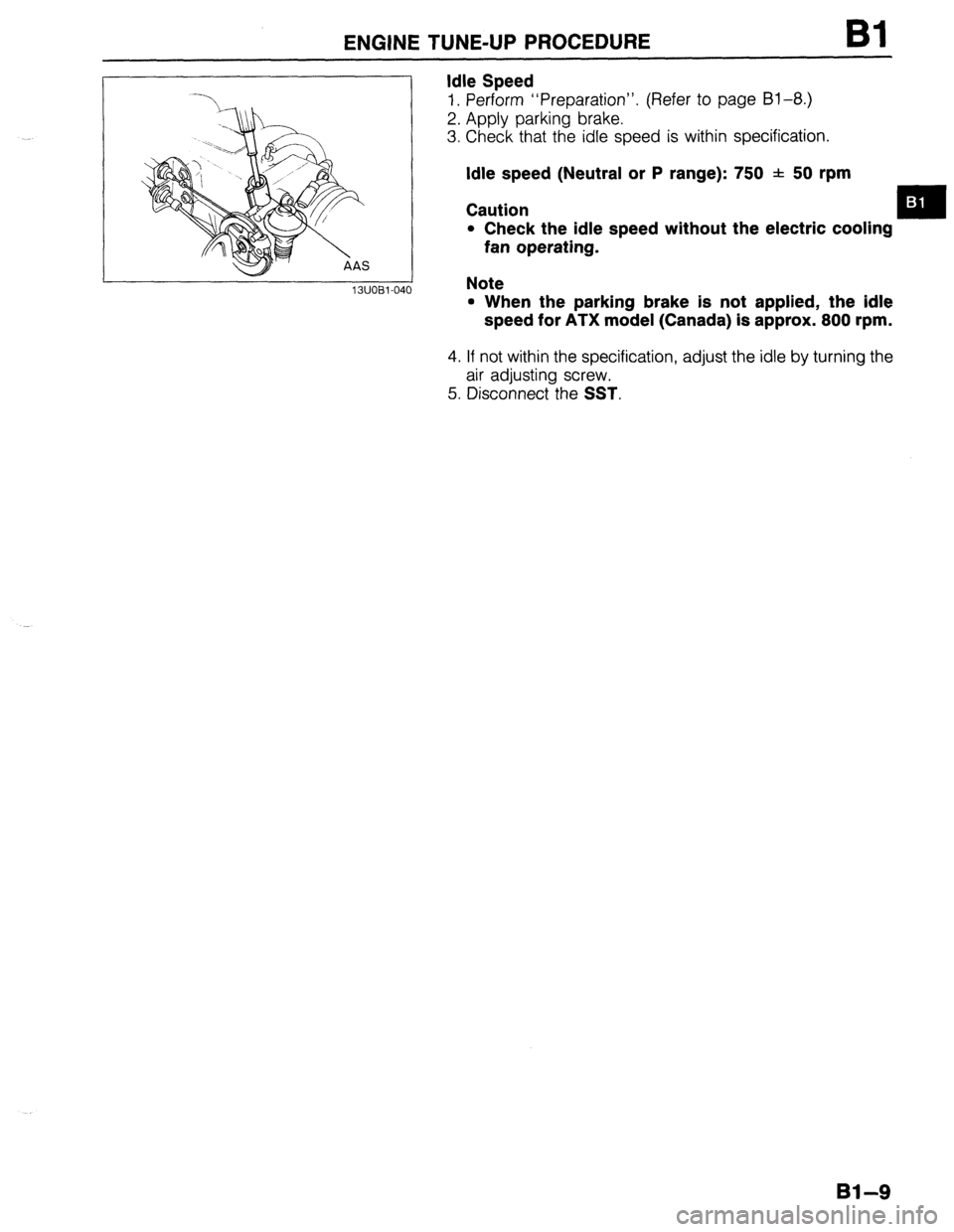
4. If not within the specification, adjust the idle by turning the
air adjusting screw.
5. Disconnect the
SST.
Bl-9
Page 40 of 1164
Bl COMPRESSION
COMPRESSION
If the engine exhibits low power, poor fuel economy, or poor idle, check the following:
1. Ignition system (Refer to Section G.)
2. Compression
3. Fuel system (Refer to Section F.)
23UOBl-01
23UOBl-06
23UOBl-014 23UOBl-012
INSPECTION
1. Check that the battery is fully charged. Recharge it if neces-
sary. (Refer to Section G.)
2. Warm up the engine to normal operating temperature.
3. Turn the engine OFF.
4. Remove all spark plugs.
5. Disconnect the ignition coil connector.
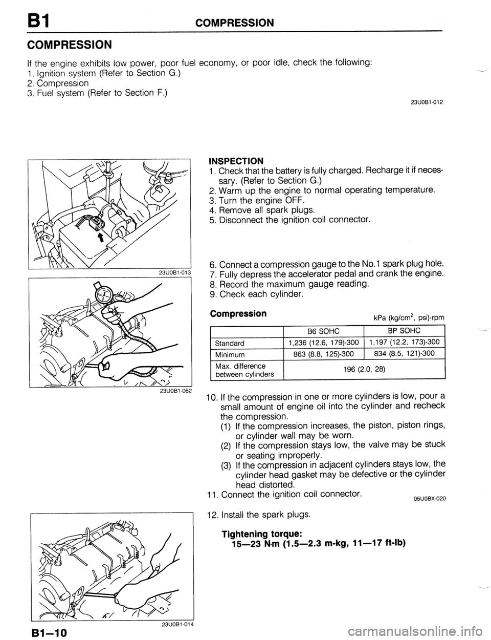
6. Connect a compression gauge to the No. 1 spark plug hole.
7. Fully depress the accelerator pedal and crank the engine.
8. Record the maximum gauge reading.
9. Check each cylinder.
Compression kPa (kg/cm*, psi)-rpm
10. If the compression in one or more cylinders is low, pour a
small amount of engine oil into the cylinder and recheck
the compression.
(1) If the compression increases, the piston, piston rings,
or cylinder wall may be worn.
(2) If the compression stays low, the valve may be stuck
or seating improperly.
(3) If the compression in adjacent cylinders stays low, the
cylinder head gasket may be defective or the cylinder
head distorted.
11. Connect the ignition coil connector.
12. Install the spark plugs.
05UOBX-020
Tightening torque:
15-23 N*m (1 S-2.3 m-kg, 11-17 ft-lb)
Bl-10
Page 41 of 1164
ON-VEHICLE MAINTENANCE Bl
ON-VEHICLE MAINTENANCE
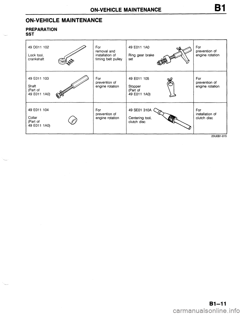
PREPARATION
SST
49 DO1 1 102
Lock tool,
crankshaft For
removal and
installation of
timing belt pulley 49 EOll 1AO
Ring gear brake
set For
prevention of
engine rotation
49 EOll 103
For
49 EOl 1 105
For
prevention of
prevention of
Shaft
engine rotation
Stopper
engine rotation
(Part of
(Part of
49 EOl 1 1AO)
49 EOI 1 1AO)
49 EOll 104
For
49 SE01 310A
For
prevention of
installation of
Collar
engine rotation
Centering tool,
clutch disc
(Part of
clutch disc
49 EOl 1 1 AO)
23UOBl-01
81-11
Page 45 of 1164
ON-VEHICLE MAINTENANCE Bl
Steps After Installation
1. Connect the negative battery cable.
2. Start the engine and check as follows:
l Ignition timing. (Refer to page 91-8.)
03UOBl-026
. .
81-15
Page 46 of 1164
Bl ON-VEHICLE MAINTENANCE
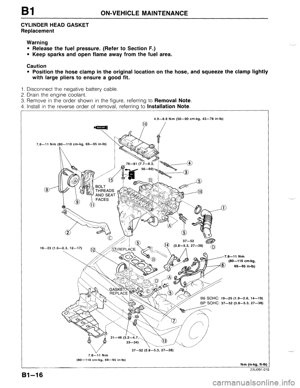
CYLINDER HEAD GASKET
Replacement
Warning
l Release the fuel pressure. (Refer to Section F.)
l Keep sparks and open flame away from the fuel area.
Caution
l Position the hose clamp in the original location on the hose, and squeeze the clamp lightly
with large pliers to ensure a good fit.
1. Disconnect the negative battery cable.
2. Drain the engine coolant.
3. Remove in the order shown in the figure, referring to Removal Note.
4. Install in the reverse order of removal, referring to Installation Note.
7.8-11 N.m
16-23 (1 4.9-8.8 N.m (50-90 cm-kg, 43-78 in-lb)
(80-l 10 cm-kg, 69-95 in-lb)
L
.8-11 N.m
(80-110 cm-kg,
69-95 in-lb)
-25 (1.9-2.6, 14-19)
BP SOHC: 37-52 (3.8-5.3, 27-38)
37-52 (3.8-5.3, 27-38)
7.8-11 N.m
(80-l 10 cm-kg, 89-95 in-lb)
N-m (m-kg, ft-lb)
23UOBl-01
81-16
Page 49 of 1164
.
ON-VEHICLE MAINTENANCE
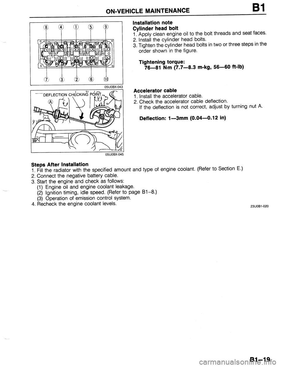
Installation note
Cylinder head bolt Bl
1. Apply clean engine oil to the bolt threads and seat faces.
2. Install the cylinder head bolts.
3. Tighten the cylinder head bolts in two or three steps in the
order shown in the figure.
Tightening torque:
76-61 N#m (7.7-6.3 m-kg, 56-60 f&lb)
Accelerator cable
1. Install the accelerator cable.
2. Check the accelerator cable deflection.
If the deflection is not correct, adjust by turning nut A.
Deflection: I-3mm (0.04-0.12 in)
Steps After Installation
1. Fill the radiator with the specified amount and type of engine coolant. (Refer to Section E.)
2. Connect the negative battery cable.
3. Start the engine and check as follows:
(1) Engine oil and engine coolant leakage.
(2) Ignition timing, idle speed. (Refer to page 81-8.)
(3) Operation of emission control system.
4. Recheck the engine coolant levels.
2311081-020
Bl-19
Page 51 of 1164

ON-VEHICLE MAINTENANCE Bl
Removal note
Rocker arm and rocker shaft assembly
1. Loosen the rocker arm bolts in two or three steps in the or-
der shown in the figure.
2. Remove the rocker arms and rocker shaft assembly.
3. Code all rocker arms and springs so that they can be rein-
stalled in the same places from which they were removed.
I
23UOBi-02 1
Installation note
HLA
1. Pour engine oil into the oil reservoir in the rocker arm.
2. Apply engine oil to the new HLA.
3. Install the HLA in the rocker arm.
Caution
l Be careful not to damage the O-ring when installing.
Oli RESERVOIR
o3uoB1-o?
Rocker arm and rocker shaft assembly
B6 SOHC
1. Assemble the rocker arm and rocker shaft assembly as
shown in the figure. No.1 CYLINDER No.4 CYLINDEF
[ ’ ” 0 D 0
0311081-034
Caution
l Be sure both rocker arm shaft oil holes face
downward.
l The installation bolt holes are different for the ex-
haust and intake sides as shown in the figure. No.1 CYLINDER
No.4 CYLINDER
INTAKE
l---A--l
0 = ‘, I I
Y Y
0 \L
.a Y
r Y)
/
6
EXHAUST
A>B
Note
l There are two types of rocker arms with different
offsets. One type for No.1 and No.2 cylinders ex-
haust and intake. And the other for cylinders No.3
and No.4.
No. 1.2 CYLINDERS No.3,4 CYLINDERS
(IN & EX) (IN & EX)
81-21
Page 52 of 1164

Bl ON-VEHICLE MAINTENANCE
8 e
93UOlA.08
EX
03UOBl-035
HEAD COVER
)
23UOBl-023
Steps After Installation
1, Connect the negative battery cable.
2. Start the engine and fully warm up.
3. Verify that there is no tappet noise. 2. Install the rocker arm and rocker shaft assembly.
Caution
l The bolts must be tightened gradually and in the or-
der shown in the figure.
Tightening torque:
22-28 N-m (2.2-2.9 m-kg, 18-21 ft-lb)
BP SOHC
1. Assemble the rocker arm and rocker shaft assembly as
shown in the figure.
Caution
l Face the rocker shaft identification mark upward.
l The installation bolt holes are different for the ex-
haust and intake sides.
Identification mark
IN . . . . . . . . . . White
EX . . . . . . . . . . . Blue
2. Install the rocker arm and rocker shaft assembly.
3. Tighten the rocker arm bolts in two or three steps in the or-
der shown in the figure.
Tightening torque:
22-28 Nsrn (2.2-2.9 m-kg, 16-21 ft-lb)
Cylinder head cover
1. Install the cylinder head cover.
Tightening torque
Bolt @:
4.9-8.8 N-m (50-90 cmikg, 43-78 in-lb)
Bolt @:
7.8-l 1 Nnrn (80-l 10 cm-kg, 69-95 in-lb)
Caution
l If the head cover gasket is reused, apply sealant in
the groove as shown.
03UOBl-038
.-
Bl-22