oil type MAZDA PROTEGE 1992 Owner's Manual
[x] Cancel search | Manufacturer: MAZDA, Model Year: 1992, Model line: PROTEGE, Model: MAZDA PROTEGE 1992Pages: 1164, PDF Size: 81.9 MB
Page 697 of 1164

PARKING BRAKE SYSTEM
PARKING BRAKE SYSTEM
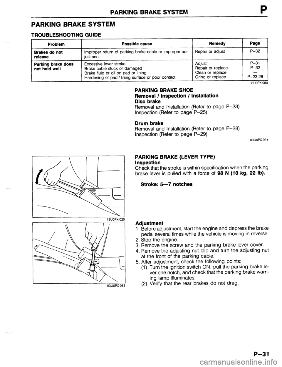
TROUBLESHOOTING GUIDE
Problem
Brakes do not
release
Parking brake does
not hold well Possible cause
Improper return of parking brake cable or improper ad-
justment
Excessive lever stroke
Brake cable stuck or damaged
Brake fluid or oil on pad or lining
Hardening of pad / lining surface or poor contact Remedy Repair or adjust
Adjust
Repair or replace
Clean or replace
Grind or replace Page P-32
P-31
P-32
P-i,28
ONOPX-080
PARKING BRAKE SHOE
Removal / Inspection / Installation
Disc brake
Removal and Installation (Refer to page P-23)
Inspection (Refer to page P-25)
Drum brake
Removal and Installation (Refer to page P-28)
Inspection (Refer to page P-29)
03u0Px-081
13UOPX-021
03UOPX-08
PARKING BRAKE (LEVER TYPE)
Inspection
Check that the stroke is within specification when the parking
brake lever is pulled with a force of 98 N (IO
kg, 22 lb).
Stroke: 5-7 notches
Adjustment
1. Before adjustment, start the engine and depress the brake
pedal several times while the vehicle is moving in reverse.
2. Stop the engine.
3. Remove the screw and the parking brake lever cover.
4. Remove the adjusting nut clip and turn the adjusting nut
at the front of the parking cable.
5. After adjustment, check the following points:
(1) Turn the ignition switch ON, pull the parking brake le
ver one notch, and check that the parking brake warn-
ing lamp illuminates.
(2) Verify that the rear brakes do not drag.
P-31
Page 703 of 1164

WHEELS AND TIRES
WHEELS AND TIRES
SPECIAL NOTES ABOUT WHEELS AND TIRES
1. Do not use wheels or tires other than the specified types.
2. Aluminum wheels are easily scratched. When washing them, use a soft cloth, never a wire brush. If the
vehicle is steam cleaned, do not allow boiling water to contact the wheels.
3. If alkaline compounds (such as saltwater or road salts) get on aluminum wheels, wash them as soon as
possible to prevent damage. Use only a neutral detergent.
9MUOQX-004
NOTES REGARDING TIRE REPLACEMENT
Note the following points when tires are to be removed from or mounted onto the wheels.
1. Be careful not to damage the tire bead, the rim bead, or the edge of the rim.
2. Use a wire brush, sandpaper, or cloth to clean and remove all rust and dirt from the rim edge and the
rim bead.
3. When cleaning aluminum wheels, use a soft cloth, never a wire brush or sandpaper.
4. Remove any pebbles, glass, nails, and other foreign items embedded in the tire tread.
5. Be sure the air valve is installed correctly.
6. Apply a soapy solution to the tire bead and the edge of the rim.
7. After mounting a tire onto a wheel, inflate the tire to 250-300 kPa (2.55-3.06 kg/cm2, 35.55-42.66
psi). Check to be sure that the bead is seated correctly onto the rim and that there are no air leaks. Then
reduce the pressure to the specified level.
8. If a tire iron is used to change a tire on an aluminum wheel, be sure to use a piece of rubber between
the iron lever and the wheel to avoid damage to the wheel. Work should be done on a rubber mat, not
on a hard or rough surface.
03UOQX-004
23UOOX-003
TIRE
I
AIR VALVE
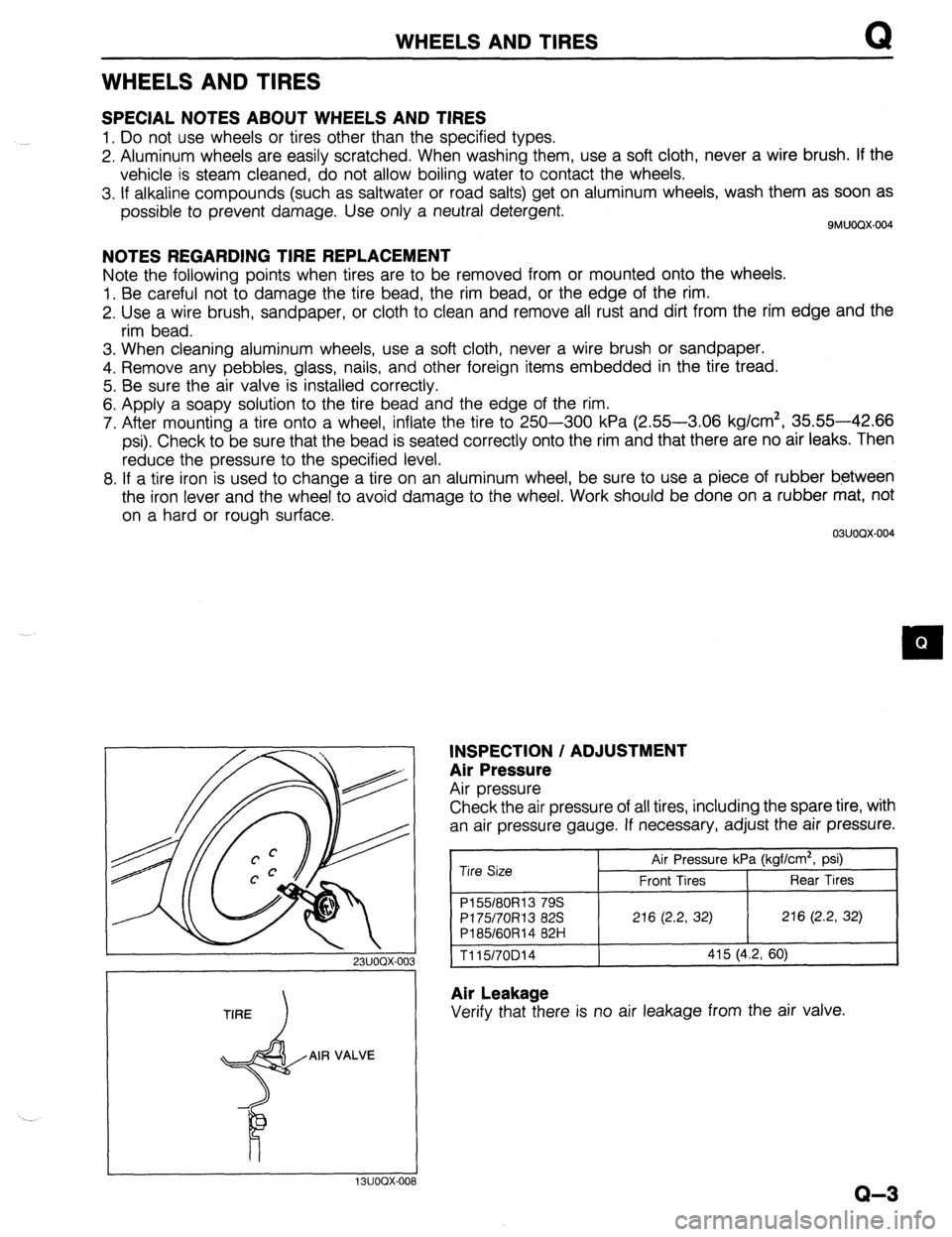
INSPECTION / ADJUSTMENT
Air Pressure
Air pressure
Check the air pressure of all tires, including the spare tire, with
an air pressure gauge. If necessary, adjust the air pressure.
Tire Size Air Pressure kPa (kgf/cm2, psi)
Front Tires Rear Tires
P155180R13 79s
PI 75/70R13 82s 216 (2.2, 32) 216 (2.2, 32)
P185/60R14 82H
1115/70D14 415 (4.2, 60)
Air Leakage
Verify that there is no air leakage from the air valve.
I I 13UOOX-008
Q-3
Page 710 of 1164

R OUTLINE
OUTLINE
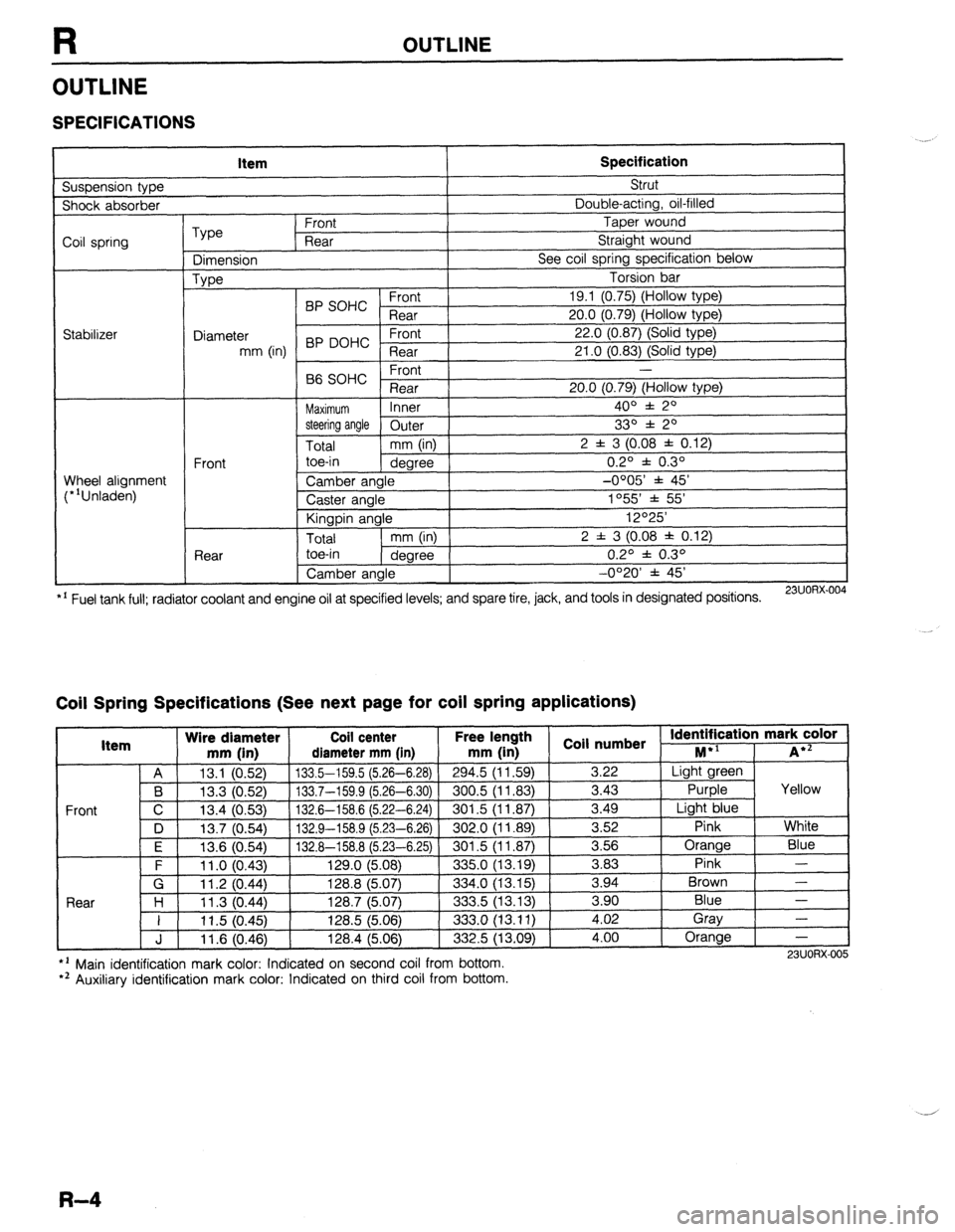
SPECIFICATIONS
Suspension type Item Specification Strut
Shock absorber Double-acting, oil-filled
Coil spring
Stabilizer Type Front Taper wound
Rear Straight wound
Dimension See coil spring specification below
Type Torsion bar
BP SOHC Front 19.1 (0.75) (Hollow type)
Rear 20.0 (0.79) (Hollow type)
Diameter 22.0 (0.87) (Solid type)
mm (in) BP DOHC ;eTrt
21 .O (0.83) (Solid type)
P ,
-
66 SOHC rronr
Rear 20.0 (0.79) (Hollow type)
Maximum Inner 400 f 20
steering angle
Outer 330 f 20
Total mm (in) 2 f 3 (0.08 f 0.12)
Front toe-in
degree 0.2O f 0.3O
Wheel alignment
(*‘Unladen) Camber angle -0005’ f 45’
Caster angle 1055 * 55’
Kingpin angle 12O25’
Total mm (in) 2 f 3 (0.08 * 0.12)
Rear toe-in
degree 0.2O f 0.3O
Camber angle -0°20’ f 45’
*’ Fuel tank full; radiator coolant and engine oil at specified levels; and spare tire, jack, and tools in designated positions.
23UORX.004
Coil Spring Specifications (See next page for coil spring applications)
I Item Wire diameter Coil center Free lel.=-. .
mm iin1 rliamotor mm [in mm (in 1 coil numbs
Front
nath
1 _ . . *St Identification mark color +l
., . . . . I...,
-*.....-.“, * . . . . . ,..-, -....- I--‘, M iA*=
A 13.1 (0.52) 133.5-159.5 (5.26-6.28)
294.5 (11.59) 3.22 Light green
B 13.3 (0.52) 133.7-159.9 (5.26-6.30) 300.5 (11.83)
3.43 Purple Yellow
C 13.4 (0.53)
132.6-158.6 (5.22-6.24) 301.5 (11.87) 3.49
Light blue
D 13.7 (0.54)
132.9-158.9 (5.23-6.26) 302.0 (11.89) 3.52
Pink White
I F I 12f3 Kl5Al I 1.17 A-l!% 8 f!i PR-Fi 751
I RrIl .5 II 1 6x71 I 3.56 Orange
Blue
3 83 Pink -
Brown - .“._ \“.- .,
. “W.., ~ - -. - \-. -- -. - -, -- .-
\’ .‘-‘I t
F 11 .o (0.43) 129.0 (5.08)
335.0 (13.19) -.--
G 11.2 (0.44) 128.8 (5.07)
334.0 (13.15) 3.94
Rnnr l-4
1 I ? 07 AA 1387 /5n7
.?m !i 113 1% 3 an Blue - I I I I .” \v.-7, I&V., \V.“., ---.., \.-. .-, I 11.5 (0.45) 128.5 (5.06)
333.0 (13.11) i:oi Gray
-
J 11.6 (0.46) 128.4 (5.06)
332.5 (13.09) 4.00 Orange
-
l ’ Main identification mark color: Indicated on second coil from bottom.
*’ Auxiliary identification mark color: Indicated on third coil from bottom. 23UORX-005
R-4
Page 866 of 1164

T
ELECTRICAL SYMBOLS
Switches and Relays OUTLINE
There is an NC (normally closed) and NO (normally open) indication for switches and relays which shows
when no change of operation conditions has occurred.
Relay Switch
NO type relay NC type relay NO switch NC switch
Not in operation
(No power supply) +E+ #Fig -o-- -da--
ax ax
STOP
FLOW STOP FLOW
In operation
(Power supply) * !jiij! kiig 6 dLe
cw r”X
FLOW STOP FLOW STOP
Other Electrical Symbols
BATTERY
THERMISTER DIODE CONDENSER
Q
M
MOTOR I
T-10
l-
BODY GROUND
COIL, SOLENOID i
0 8 HOLDER BOX
FUSE
RESISTOR
1
T
FUSIBLE LINK
1 i 1
VARIABLE RESISTOR
LIGHT
HEATER
69G15X-O(
Page 1019 of 1164

TECHNICAL DATA TD
r-
RP sm.lc: I Item
Crankpin bearing Engine
86 SOHC
I -. VW.._
Crankpin bearing oil clearance mm (in) Standard 0.028-0.068 (0.001 l-0.0027)
Maximum 0.10 (0.004)
Available undersized bearing mm (in)
0.25 (O.OlO), 0.50 (0.020) 0.75 (0.030) Thrust bearing
Crankshaft end play mm (in) Standard 0.080-0.282 (0.0031-0.0111)
Maximum 0.30 (0.012)
Standard size 2.500-2.550 (0.0984-0.1004)
Bearing width mm (in) 0.25 (0.010) oversize 2.625-2.675 (0.1033-0.1053)
0.50 (0.020) oversize 2.750-2.800 (0.1083-0.1102)
0.75 (0.030) oversize 2.875-2.925 (0.1132-0.1152)
1 Timing belt
Belt deflection mm (in)/98 N (10 kg, 22 lb) 1 11 .o-13.0 (0.43-0.51) 82.
ENGINE (BP DOHC) Item
Type
Cylinder arrangement and number BP DOHC
Gasoline, 4-cycle
In-line 4-cylinders
-. I
Combustion chamber
Valve svstem DOHC, belt-d
Bore x Stroke
Total piston displacement ventroot
riven
(3.2:
mm (in) 1 83.0 x 85.0
cc (cu in) ]
7x3.35)1 1,839 (112.2)
I 16 valves I 9.0
-300
mn Compression ratio
Standard 1,256 (12.8, 182)
Compression pressure Minimum 883 (9.0, 128)-Z kPa (kglcm2,
Psi)-rPm
Maximum dif
‘ference
between eat -, h cvlinder 196 (2.0, 28)
IN Open BTDC 5O
Valve timing Close ABDC 48’
EX Open BBDC 56O
Close ATDC .4 In
IY-
IN
mm (in) EX 0 Maintenance-l
Valve clearance
0 Maintenance-i ‘ree
‘me Cylinder head
Height mm (in)
Distortion mm (in)
Grinding mm (in)
Standard
Cylinder head-to-HLA clearance mm (in) Maximum Valve and valve guide 133.8-134.0 (5.268-5.276)
0.10 (0.004) max.
0.10 (0.004) max.
0.025-0.066 (0.0010-0.0026)
0.18 (0.0071)
Valve head diameter IN
mm (in) EX 32.9-33,l (1.295-l ,303)
27.85-28.15 (1.096-1.108)
Valve head margin thickness IN
mm On) Fx 0.9 (0.0354)
1 .o fO.0393)
1 Valve face angle . .
I
FX I I
Valve length IN
Standard 101.34 (3.9898)
mm (in) Minimum 100.84 (3.9701)
Standard 101.44 (3.9937) I -, .
I
Valve stem diameter EX
Minimum loo.94 i3.974oj
IN
mm (in) - EX 5.970-5.985 (0.2350-0.2356)
5.965-5.980 (0.2348-0.2354)
mm (in) I
. , , 6.01-6.03 (0.23 166-0.2374)
1 IN
I 0.025-0.060 (0.0010-0.0024)
3.0012-0.0026)
( Maximum 0.20 (0.008)
I
TD-5
Page 1022 of 1164

TECHNICAL DATA
D. LUBRICATION SYSTEM
Item I I bhricatinn mothnd
Engine
B6 SOHC BP SOHC
Force-fed BP DOHC 1
Requlated pressure kPa (kg/Cm”, p
Inner rotor tooth tip to outer rotor Standard
I-‘---- -.----,
clearance mm (in) Maximum 0.20 (0.0078)
Outer rotor to body clearance mm (in) Standard 0.09-0.18 (0.0035-0.0071)
Maximum 0.22 (0.0087)
Side clearance mm (in) Standard 0.03-0.11 (O.pniq n nnn=’
Maximum n4rl ‘-
“” I r-“.““+..I,
I “. I ‘t (U.0055)
I
1
Oil filter
_ Type
Relief pressure differential
Engine oil
I
Capacity
liters (US qt, Imp qt)
Grade
I Viscosity Full-flow, paper element
kPa (kg/cm’, psi) 1 78-l 18 (0.8-I .2, 1 l-l 7) Tntal /An, nnr*inol 3.4 (3.6, 3.0) 1 4.0 (4.2, 3.5)
3.0 (3.2, 2.6) 1 3.6 (3.8, 3.2)
VII 111Lb1 0.17 (0.18, 0.15)
API Service SG Energy Conserving II (ECQ
1
SA!f InW-Xl 1~ Above -25% (-13OF _ .-.. --
I
I
number
1 Below O’C (32OF) SAE 5W-30
1
E. COOLING SYSTEM
Cooling method EnginelTransaxle
MTX ] ATX 1 MTXl
Water-cooled, forced circulation
J B6 SOHC BP SOHC BP DOHC
, ATX 1 MTX ) ATX
LThermostat
Type Opening temperature
Full-open temperature
Full-open lift
Radiator
_ Type
Cap valve opening pressure
Cooling circuit checking pressure Wax, two-stage
“C (OF) Sub: 83.5-86.5 (182--188), Main: 86.5-89.5 (188-193)
OC (OF) 100 (212)
mm (in) Sub: 1.5 (0.06) min., Main: 8.0 (0.31) min.
Corrugated fin
kPa (kg/cm2, psi) 74-103 (0.75-1.05, 11-15)
kPa (kg/cm’, psi) 103 (1.05, 15)
~..
Cooling fan
Type Electric .-
Number of blades 4
_.---- _I___-
Outer diameter mm (in) 320 (12.6)
--_ ~~-
Capacity w-v 80-12 - 160-12 80-l 2 160-12
6.6 Hi : 13.3
6.6 Hi : 13.3
Current A
Low : 8.8 Low : 8.8
_------ ._____
Water thermoswitch
“c (OF) 1
OFF-ON 97 (207)
I--.
Radiator thermoswitch
__-I____-
OFF+ON “C (OF) 1 1105 (221)( - (105 (221)
TD-8
Page 1023 of 1164

TECHNICAL DATA TD
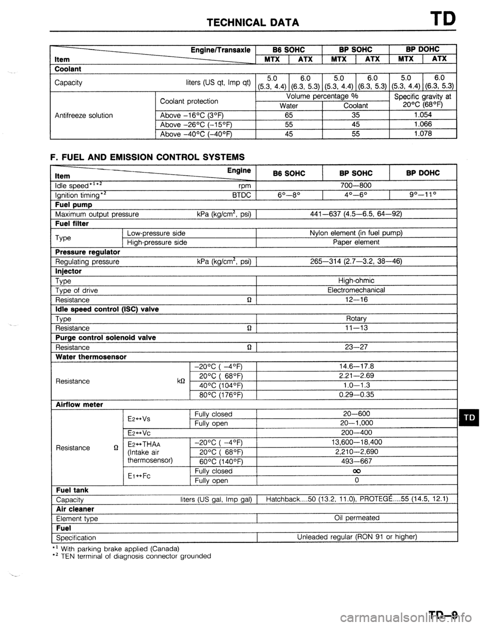
Item
Coolant Engine/Transaxle B6 SOHC BP SOHC BP DOHC
MTX 1 ATX 1 MTX 1 ATX 1 MTX 1 ATX
Capacity
liters tus qt, Imp qt) (5Z.4) (8.E.3) (5&4) (SE.3) (5.?i.4) (S.E.3)
Coolant protection Volume percentage %
Specific gravity at
Water Coolant 20% (68OF)
Antifreeze solution Above -16OC (3OF)
65 35 1.054
Above -26OC (-15OF) 55 45 1.066
I Above -4OOC (-40°F) 45 55
1.078
F. FUEL AND EMISSION CONTROL SYSTEMS Item
idle speed*‘**
Ignition timing** Fuel pump
Maximum output pressure Fuel filter Engine
B6 SOHC BP SOHC BP DOHC
vm 700-800
BTDC 6O--8O 4O---6O 90-l 10
kPa (kg/cm*, psi) 1 441-637 (4.5-6.5, 64-92) ‘Type
Low-pressure side Nylon element (in fuel pump)
High-pressure side Paper element Pressure regulator
Regulating pressure kPa (kg/cm*, psi) 1 265-314 (2.7-3.2, 38-46) Injector
Type
High-ohmic
Type of drive Electromechanical
Resistance n 12-16 Idle speed control (ISC) valve
Type
Rotary
Resistance n ] 11-13 Purge control solenoid valve
Resistance n 1 23-27 Water thermosensor
-20°C( -4OF) 14.6-17.8
Resistance k6 20°C( 68QF) 2.21-2.69
40% (104OF) 1.0-l .3
80°C(1760F) 0.29-0.35 Airflow meter
E2++Vs Fully closed 20-600 q D Fully open 20-l ,000
E~HVC 200-400
Resistance g Ez++THAA -2O%(-4OF) 13,600-18,400
(Intake air 20%( 68OF) 2,210-2,690
thermosensor)
60°C(1400F) 493-667
Eic*Fc Fully closed 00
Fully open 0 Fuel tank
Capacity liters (US gal, Imp gal) I
Hatchback 50 (13.2, 11.0) PROTEGE . . . . 55 (14.5, 12.1) Air cleaner
Element type Oil permeated Fuel
Specification Unleaded regular (RON 91 or higher)
*’ With parking brake applied (Canada)
*’ TEN terminal of diagnosis connector grounded
TD-9
Page 1024 of 1164

TD TECHNICAL DATA
G. ENGINE ELECTRICAL SYSTEM
3attery Dark
current*’
Alternator 86 SOHC BP SOHC
I BP DOHC
MTX 1 ATX 1 MTX 1 ATX
Voltage V 12
Type and capacity (20-hour rate) 55D23L (60AH) 1 55D23L (60AH)
mA Max. 20.0
Type A.C
output V-A 12-65
Regulator type Transistorized (built-in IC regulator)
Regulated voltage V 14.1-14.7
Brush length Standard 21.5 (0.846)
mm (in) Minimum 8.0 (0.315)
Drive belt deflection
New 8-Q (0.31-0.35)
;riL’F,i Used Q-10 (0.35-0.39)
Coaxial
Type Direct Direct Coaxial
reduction Direct
reductior
Starter output V-kW 12-0.85 12-0.95 12-1.4 12-0.95 12-1.4
Brush length Standard 17 (0.67) 17 (0.67) 17.5 (0.69) 17 (0.67) 17.5 (0.69
mm (in) Minimum 11.5 (0.453) 11.5 (0.453) 10.0 (0.39) 11.5 (0.453) 10.0 (0.39
Distributor Electronic spark advance (photo diode)
Ignition timing BTDC
(TEN terminal of diagnosis connector grounded) 6O-8O 4O-6O 9”-11 O
Ignition coil Resistance Primary coil winding 0.81 -O.QQg
(at 20% [68OF]) Secondary coil winding lo-16 kg
SK&E-1 1 BKR5E-11
NGK
BKRGE-11 BKRGE-11
BKR7E-11
Spark plug Type
NIPPONDENSO KlGPR-Ull
K20PRUll KlGPR-Ull
K20PRUll
K22PRUll *:
. Plug gap
Firing order mm (in) 1.0-l .l (0.039-0.043)
l-3-4-2
---
’ Dark current is the constant flow of current while the ignition switch IS UFF.
(i.e engine control unit, audio, etc.) ..-
._*
T&l 0
Page 1031 of 1164

TECHNICAL DATA TD
1 Throttle condition 1
nrllm pn-t
Mode Rr _ me/ flhrottle sensor 1 Shift 1 -.- -*r2d rpm
Vehicle speed I km/h (mohl , . ,
I
ioltage) 1 B6 sot
iC 1 BP SOHC 1 BP DOHC
66 SOHC 1 BP SOHC 1 BP
I I I
’ ni - n9 I’) 7nn-1 “50 2,500-3,05012,700-3.3001 I I DOHC
Fully opened 27-33 (17-201
3 D (4.0 volt) 50 2,050-2,55012,200-2,750]
40-50 i25-31 j
e I 300-500 1 450-650 / Q-15 16-9) 112-18 (7-111
00 3,250-3,45013,550-3.800~91-97 f56-60&G10’4 (61-64)hOO-106;62-&\I
s
i- f Fully closed
(0.5 volt)
YI -l&c
L, r vv-“,L
Dz + D3 2,150-2,7
D3 -+ DI 300--5O(
S3 -+ S2 3,200-3,4
’ L2 -+ LI 2,350-2,65012,200-2,50012,350-2.7001
43-49 ;27--3b1 ’ ‘I
M. FRONT AND REAR AXLES -
Item
Driveshaft Engine/Transaxle BP SOHC BP DOHC
Joint type
Length of shaft
Shaft diameter Front axle
Bearing play axial direction Rear axle
Bearing play axial direction Inside Tripod joint
Outside Ball joint
Right
919.3 (36.19) 918.7 (36.17) 630.7 (24.83)
mm (in) Left
637.8 (25.11) 640.2 (25.20) 621.2
637.1
(24.46) (25.08)
21.5 (0.85) 23.0 (0.91)
mm (in) 1 0.05 (0.002)
mm (in) I 0.05 (0.002)
N. STEERING SYSTEM Steering wheel
Outer diameter Item Specifications 370 (14.57)
Lock-to-lock I Steering gear
--
Type
Steering gear ratio
Backlash between rack and pinion mm (in)
N.r ’ ’ ” ’ n (cm-Kg, in-01
Preload measured by torque
*rrv~rrdl Rack and pinion
Infinite (00)
0 (0)
M/S : 0.9-l .3 (Q-13, 7.8-l 1.3)
P/S : 1.0-1.3 (10-14, 8.7-12)
Pinion preload ““l~jll~,,
9 (0.4
Preload measured by pull
scale with attachment
Limit of rack housing movement mm (in)
Distance between left and right brackets mm (in)
Rack stroke mm (in M/S : 900-l ,300 (31.8-45.9)
P/S : l,OOO-1,400 (35.3-49.4)
1.5 (0.06)
298.5 (11.75)
140 (5.511
Lubricant type (power steering)
Oil capacity (power steering) Drive belt
liter (US qt, Imp qt) I ATF: M-III or DexronW
0.8 (0.85, 0.70)
I New belt: 8-Q (0.31-0.35)
Deflection with force of 98 N (10 kg, 22 lb) mm (in) Used belt: 9-10 (0.35-0.39)
I imit: 11.5 (0.461
TD-17
Page 1033 of 1164

TECHNICAL DATA
Q. WHEELS AND TIRES
Item Specifications
Wheel
Size
Off set Standard: 13x5-J, 14x5 l/2-JJ
Temporary
mm (in) 1 _ spare: 14x4-T
45 (1.77)
I Diameter of oitch circle
mm (in) I 100 (3.94)
r I Pl
-
Inflation pressure kPa (kg/cm*, psi) Front 1 8
I 9
Runout limit
Unbalance limit mm (in) ;lii.raltLa’
a (02) ’
13 inch wheel: 11 (0.
R. SUSPENSION Item Specifications
Suspension type Strut
)e Double-acting, oil-filled
I Shock absorber tyf
Coil spring
Type
Dimension
Type Front Taper wound
Rear Straight wound
See next page
Torsion bar
I
I C.rrn,
19.1 (0.75)
20.0 (0.79)
22.0 (0.87)
21 .O f0.83)
Wheel alignment
(“‘Unladened) BP SOHC ;;a;
Diameter
mm (in) BP DOHC - ;la;t
Front -
B6 SOHC
Rear 20.0 (0.79)
Maximum Inner 4o” f 2O
steering angle Outer
Total mm (in) 2 f 3 (0.08 j
Front toe-in
dearee
.-.._
Rear
.--. I --- ~~
Camber angle
Caster angle
Kingpin angle
I Total
I mm OnI I I toe-in
1 dearee I , --U’-- 1
Camber angle
I 33O * 2O
: 0.12)
0.2O f 0.3O
-0OO5’ * 45’
1055’ * 55’
12O25’
2 f 3 (0.08 f 0.12)
0.2O f 0.3O
-0°20’ f 45’
l ’ Fuel tank full; radiator coolant and engine ail at specified level; and spare tire, jack, and tools in designated posmons.
TD-19