power steering MAZDA PROTEGE 1992 Workshop Manual
[x] Cancel search | Manufacturer: MAZDA, Model Year: 1992, Model line: PROTEGE, Model: MAZDA PROTEGE 1992Pages: 1164, PDF Size: 81.9 MB
Page 12 of 1164
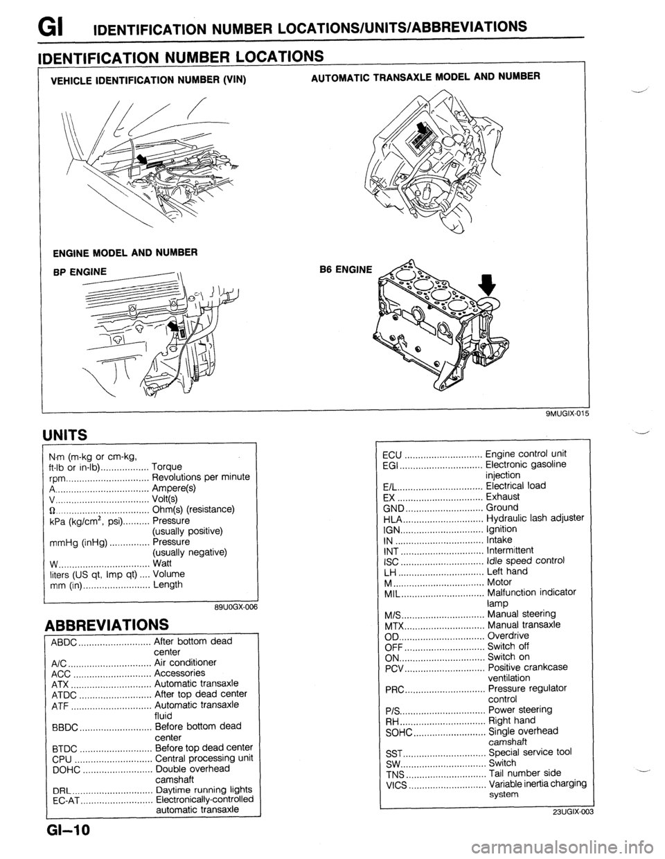
GI IDENTIFICATION NUMBER LOCATIONS/UNITS/ABBREVlATlONS
VEHICLE IDENTIFICATION NUMBER (VIN) AUTOMATIC TRANSAXLE MODEL AND NUMBER
ENGINE MODEL AND NUMBER
B6 ENGINE
IDENTIFICATION NUMBER LOCATIONS
UNITS
I
N.m (m-kg or cm-kg,
ft-lb or in-lb) . . . . . . . . . . . . . . . . . . Torque
rpm ._..,,,.............,.......... Revolutions per minute
A . . . . . . . . . . . . . . . . . Ampere(s)
v, . . . . . . . . . . . . . .
Volt(s)
$2 _....._..,......................... Ohm(s) (resistance)
kPa (kg/cm2,
psi) . . . . . . . . . . Pressure
(usually positive)
mmHg (inHg) . . . . . . . . . . . . . . . Pressure
(usually negative)
W.. . . . . . . . . . . .
Watt
liters (US qt, Imp qt) ,... Volume
mm (in) ..,......,...,........... Length
89UOGX-00
ABBREVIATIONS
ABDC . . . . . . . . . . . . . . . . . . . . .
After bottom dead
center
A/C . . . . . . . . . . . . . . . . . . . . . . . . . . . . . . .
Air conditioner
ACC ..,.,...... 3 . . . . . . . . . . . . . . . . . Accessories
ATX . . . . . . . . . . . . . . . . . . . . . . . . . . . . . . Automatic transaxle
ATDC ..,,...,...,............... After top dead center
ATF . . . . . . . . . . . . . . . . . Automatic transaxle
fluid
BBDC ,,..,.......,...,......,... Before bottom dead
center
BTDC .,......,...............,.. Before top dead center
CPU ..,,.......,...,..........,.. Central processing unit
DOHC ..,...,..,............,,.. Double overhead
camshaft
DRL ____.......................... Daytime running lights
EC-AT .,_.......,............,,.. Electronically-controlled
automatic transaxle
L
GI-10
ECU ............................. Engine control unit
EGI ............................... Electronic gasoline
injection
E/L.. .............................. Electrical load
EX ................................ Exhaust
GND.. ........................... Ground
HLA.. ............................ Hydraulic lash adjuster
IGN ............................... Ignition
IN ................................. Intake
INT ............................... Intermittent
ISC
............................... idle speed control
LH ................................ Left hand
M..
................................ Motor
MIL..
............................. Malfunction indicator
lamp
M/S..
............................. Manual steering
MTX.. ............................ Manual transaxle
OD ................................ Overdrive
OFF.. ............................ Switch off
ON.. .............................. Switch on
PCV.. ............................ Positive crankcase
ventilation
PRC..
............................ Pressure regulator
control
PIS ................................ Power steering
RH..
.............................. Right hand
SOHC.. .........................
z;;kiprhead
SST ............................... Special service tool
SW.. .............................. Switch
TNS
.............................. Tail number side
VICS
............................. Variable inertia charging
system
23UGIX-00
Page 20 of 1164
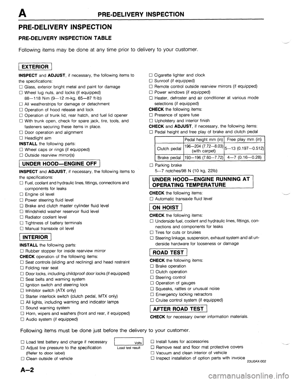
PRE-DELIVERY INSPECTION
PRE-DELIVERY INSPECTION
PRE-DELIVERY INSPECTION TABLE
Following items may be done at any time prior to delivery to your customer.
INSPECT and ADJUST, if necessary, the following items to
the specifications:
0 Glass, exterior bright metal and paint for damage
Cl Wheel lug nuts, and locks (if equipped)
88-118 N.m (9-12 m-kg, 65-87 ft-lb)
q All weatherstrips for damage or detachment
0 Operation of hood release and lock
0 Operation of trunk lid, rear hatch, and fuel lid opener
Cl With trunk open, check for spare jack, tire, tools, and
fasteners securing these items in place.
Cl Door operation and alignment
Cl Headlight aim
INSTALL the following parts:
Cl Wheel caps or rings (if equipped)
q Outside rearview mirror(s)
1 UNDER HOOD-ENGINE OFF )
INSPECT and ADJUST, if necessary, the following items to
the specifications:
0 Fuel, coolant and hydraulic lines, fittings, connections and
components for leaks
Cl Engine oil level
0 Power steering fluid level
0 Brake and clutch master cylinder fluid level
El Windshield washer reservoir fluid level
Cl Radiator coolant level
Cl Tightness of battery terminals
Cl Manual transaxle oil level
riizmiq
INSTALL the following parts:
Cl Rubber stopper for inside rearview mirror
CHECK operation of the following items:
0 Seat controls (sliding and reclining) and head restraint
Cl Folding rear seat
0 Door locks, including childproof door locks (if equipped)
Seat belts and warning system
Cl Ignition switch and steering lock
0 Inhibitor switch (ATX only)
U Starter interlock switch (clutch pedal, MTX only)
Cl All lights, including warning and indicator lamps
Cl Sound warning system
Cl Horn, wipers and washers (front and rear, if equipped)
0 Audio system (if equipped) 0 Cigarette lighter and clock
0 Sunroof (if equipped)
II Remote control outside rearview mirrors (if equipped)
Cl Power windows (if equipped)
q Heater, defroster and air conditioner at various mode
selections (if equipped)
CHECK the following items:
Cl Presence of spare fuse
0 Upholstery and interior finish
CHECK and ADJUST, if necessary, the following items:
0 Pedal height and free play of brake and clutch pedal
Pedal height mm (in) Free play mm (in)
0 Parking brake
5-7 notches/98 N (10 kg, 22lb)
UNDER HOOD-ENGINE RUNNING AT
OPERATING TEMPERATURE
CHECK the following items:
q Automatic transaxle fluid level
[I
CHECK the following items:
Cl Underside fuel, coolant and hydraulic lines, fittings, con-
nections and components for leaks
0 Tires for cuts or bruises
0 Steering linkage, suspension, exhaust system and all un-
derside hardware for looseness or damage
[I
CHECK the following items:
0 Brake operation
0 Clutch operation
Cl Steering control
Cl Operation of gauges
q Squeaks, rattles or unusual noise
Cl Emergency locking retractors
0 Cruise control system (if equipped)
1 AFTER ROAD TEST (
CHECK for necessary owner information materials.
Following items must be done just before the delivery to your customer.
q Load test battery and charge if necessary
1 Volts 1 0 Install fuses for accessories
i.. _
0 Adjust tire pressure to the specification
Load test result cl Remove seat and floor mat protective covers
(Refer to door label) 0 Vacuum and clean interior of vehicle
0 Clean outside of vehicle q Inspect installation of option parts with invoice
23UOAX-002
A-2
Page 28 of 1164
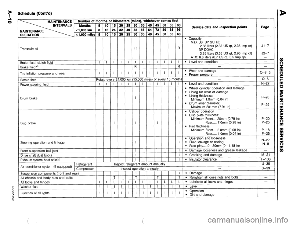
7 Schedule (Cont’d)
rile
iii
48
30
-
R
I
R !rs
25
40
25
-
-i- , whichever comes first
OPERATION MAINTENANCE Number of m
INTERVALS Months
x 1,000 km
x 1,000 miles
ii
is
G
-
i-
-
-
I
5-
T
-
-
-
-
-
-
- ii
z
ro
-
I-
-
-
I
- 45
72
45
-
-i-
-
-
I
-
ry 15 month:
I I I
A
t
A
j
milt Service data and inspection points Page
l Capacity
MTX B6, BP SOHC:
2.68 liters (2.83 US qt, 2.36 Imp qt)
BP DOHC
3.35 liters (3.55 US qt, 2.96 Imp qt)
ATX: 6.3 liters (6.7 US qt, 5.5 Imp qt)
l Level and condition
- Jl-7
J2-7
- Transaxle oil
l Wear and damaae -i- -i- -i- -
Brake fluid, clutch fluid
Brake fluid*3 -
Q-3, 5
Q-6
N-27
P-28
P-29 I I
- I
1,oo
-i
-
-
-
-
-
-
- I
G
T
-
-
-
-
-
-
- I
15,(
I Tire inflation pressure and wear l Proper pressure-
-
l Level and condition
l Wheel cylinder operation and leakage l Lining for wear or damage l Lining thickness:
Minimum 1 .Omm (0.04 in)
l Drum inner diameter. 3s) or f
I I
I
:t r
- Rotate tires
Power steering fluid
Drum brake ? every
I I
Disc brake I I
Maximum 201mm (7.91 in)
l Caliper operation l Disd plate thickness:
Minimum Front.... 20mm (0.79 in)
Rear . . . . . 7.0mm (0.28 in)
l Pad thickness:
Minimum Front.... 2.0mm (0.08 in) P-20
P-25
P-l 8
P-25
N-27
N-8 Rear . . . . . 1 .Omm (0.04 in)
l Operation and looseness l Fluid leakage or oozina
l Free play.... O--3OmmjO-1.18 in)
l Damage looseness and grease leakage
l Cracking and damage
l Insulator clearawp .-v
-
Steering operation and linkage
I
-i-
-I-
-i- Front suspension ball joint
Drive shaft dust boots
Exhaust system heat shield
Air conditioner system (if equipped) Refrigerant
Compressor
Suspension components (front and rear)
All chassis and body nuts and bolts
All locks and hinaes
Washer fluid -
M-21
F-136
u-35
u-39
-
- IY efrigerant amount ann
*. I# mspec
Inspect operation annualry -
l Damaae
l Retighten all loose nuts and bolts
l Lubricate all locks and hinges
l Level
l ODeration - Function of all lights l !%t and damage -
Page 267 of 1164
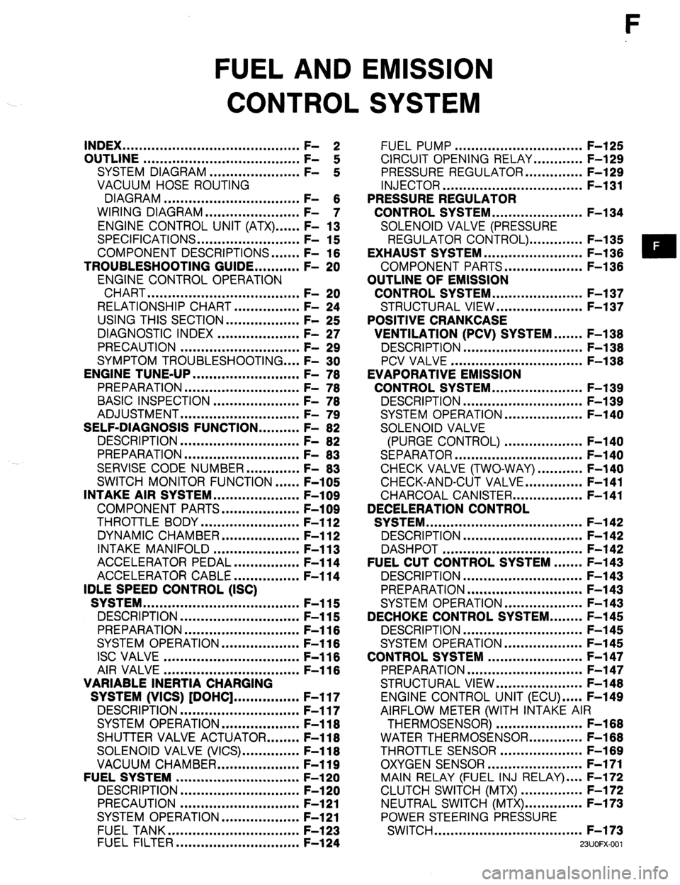
F
FUEL AND EMISSION
CONTROL SYSTEM
INDEX ...........................................
OUTLINE ...................................... ;: 2
SYSTEM DIAGRAM ...................... F-
:
VACUUM HOSE ROUTING
DIAGRAM .................................
WIRING DIAGRAM ....................... F- 6
- 7
ENGINE CONTROL UNIT (ATX) ...... F- 13
SPECIFICATIONS.. ....................... F- 15
COMPONENT DESCRIPTIONS.
...... F- 16
TROUBLESHOOTING GUIDE.. ......... F- 20
ENGINE CONTROL OPERATION
CHART
..................................... F- 20
RELATIONSHIP CHART.. .............. F- 24
USING THIS SECTION .................. F- 25
DIAGNOSTIC INDEX .................... F- 27
PRECAUTION ............................. F- 29
SYMPTOM TROUBLESHOOTING .... F- 30
ENGINE TUNE-UP
.......................... F- 76
PREPARATION ............................
F- 76
BASIC INSPECTION ..................... F- 78
ADJUSTMENT .............................
F- 79
SELF-DIAGNOSIS FUNCTION .......... F- 82
DESCRIPTION .............................
F- 82
PREPARATION
............................
F- 83
SERVISE CODE NUMBER.. ........... F- 83
SWITCH MONITOR FUNCTION ...... F-105
INTAKE AIR SYSTEM.. ................... F-109
COMPONENT PARTS.. ................. F-109
THROTTLE BODY ........................ F-l 12
DYNAMIC CHAMBER ................... F-l 12
INTAKE MANIFOLD ..................... F-l 13
ACCELERATOR PEDAL ................ F-l 14
ACCELERATOR CABLE ................ F-l 14
IDLE SPEED CONTROL (ISC)
SYSTEM ......................................
F-115
DESCRIPTION ............................. F-115
PREPARATION
............................ F-116
SYSTEM OPERATION.. ................. F-l 16
ISC VALVE ................................. F-116
AIR VALVE
................................. F-116
VARIABLE INERTIA CHARGING
SYSTEM (VICS) [DOHC] ................ F-l 17
DESCRIPTION ............................. F-117
SYSTEM OPERATION ................... F-l 18
SHUTTER VALVE ACTUATOR.. ...... F-l 18
SOLENOID VALVE (VICS). ............. F-118
VACUUM CHAMBER.. .................. F-119
FUELSYSTEM .............................. F-l 20
DESCRIPTION
............................. F-l 20
PRECAUTION ............................. F-121
SYSTEM OPERATION.. ................. F-121
FUEL TANK ................................
F-l 23
FUEL FILTER .............................. F-l 24 FUEL PUMP ............................... F-l 25
CIRCUIT OPENING RELAY.. .......... F-129
PRESSURE REGULATOR.. ............ F-129
INJECTOR .................................. F-l 31
PRESSURE REGULATOR
CONTROL SYSTEM.. .................... F-l 34
SOLENOID VALVE (PRESSURE
REGULATOR CONTROL). ............ F-l 35
EXHAUST SYSTEM ........................ F-l 36
COMPONENT PARTS.. ................. F-136
OUTLINE OF EMISSION
CONTROL SYSTEM.. .................... F-l 37
STRUCTURAL VIEW.. ................... F-l 37
POSITIVE CRANKCASE
VENTILATION (PCV) SYSTEM.. ..... F-138
DESCRIPTION .............................
F-l 38
PCV VALVE ................................ F-l 38
EVAPORATIVE EMISSION
CONTROL SYSTEM.. .................... F-l 39
DESCRIPTION ............................. F-l 39
SYSTEM OPERATION.. ................. F-140
SOLENOID VALVE
(PURGE CONTROL) ................... F-140
SEPARATOR ............................... F-l 40
CHECK VALVE (TWO-WAY) ........... F-140
CHECK-AND-CUT VALVE.. ............ F-141
CHARCOAL CANISTER.. ............... F-141
DECELERATION CONTROL
SYSTEM ...................................... F-l 42
DESCRIPTION ............................. F-l 42
DASHPOT .................................. F-142
FUEL CUT CONTROL SYSTEM ....... F-143
DESCRIPTION ............................. F-l 43
PREPARATION ............................ F-l 43
SYSTEM OPERATION.. ................. F-143
DECHOKE CONTROL SYSTEM.. ...... F-145
DESCRIPTION ............................. F-l 45
SYSTEM OPERATION ................... F-l 45
CONTROL SYSTEM ....................... F-l 47
PREPARATION ............................ F-147
STRUCTURAL VIEW.. ................... F-l 48
ENGINE CONTROL UNIT (ECU) ..... F-149
AIRFLOW METER (WITH INTAKE AIR
THERMOSENSOR) ..................... F-168
WATER THERMOSENSOR.. ........... F-168
THROTTLE SENSOR .................... F-l 69
OXYGEN SENSOR.. ..................... F-171
MAIN RELAY (FUEL INJ RELAY) .... F-172
CLUTCH SWITCH (MTX) ............... F-172
NEUTRAL SWITCH (MTX). ............. F-173
POWER STEERING PRESSURE
SWITCH .................................... F-173
WJOFX-001
Page 269 of 1164

INDEX F
1. Resonance duct
Inspection / Replacement.. ........ page F-l 09
2. Air cleaner element
Inspection ................................. page F- 79
Replacement.. ........................... page F-l 09
3. Airflow meter
(With intake air thermosensor)
Inspection
................................. page F-l 68
Replacement.. ........................... page F-l 09
4. Resonance chamber
Inspection I Replacement.. ........ page F-l 09
5. Throttle body
Inspection .................................
page F-l 12
Replacement.. ...........................
page F-l 09
6. Throttle sensor
inspection ................................. page F-l 69
Adjustment..
.............................. page F-l 69
Replacement.. ........................... page F-l 71
7. ISC valve
Inspection ................................. page F-l 16
Replacement..
........................... page F-l 09
8. Dashpot
Inspection ................................. page F-l 42
9. Dynamic chamber
Removal / Installation ................
page F-109
Inspection [DOHC] ................... page F-l 12
10. Air valve
Inspection
................................. page F-l 16
Removal / Installation ................ page F-109
11. Shutter valve actuator
Inspection ................................. page F-l 18
12. Vacuum chamber [DOHC]
Inspection ................................. page F-l 19
13. Intake manifold
Removal / Installation ................ page F-l 09
14. Injector
Inspection .................................
page F-l 31
Removal .................................... page F-131
Installation.. ............................... page F-l 33 15. Pressure regulator
Inspection ................................. page F-l 29
Replacement ............................. page F-l 30
16. Solenoid valve (Pressure regulator control)
[BP1
Inspection ................................. page F-l 35
17. Solenoid valve (VICS) [DOHC]
Inspection ................................. page F-l 18
18. Charcoal canister
Inspection ................................. page F-l 41
19. Solenoid valve (Purge control)
Inspection ................................. page F-l 40
20. Circuit opening relay
Inspection ................................. page F-l 29
Replacement ............................. page F-l 29
21. Engine control unit (ECU)
Removal / Installation ................ page F-l 49
Inspection ................................. page F-149
22. Clutch switch (MTX)
Inspection ................................. page F-l 72
Replacement.. ........................... page F-l 72
23. PCV valve
Inspection ................................. page F-l 38
24. Water thermosensor
Removal / Inspection /
Installation ............................... page F-l 68
25. Fuel filter (High-pressure side)
Replacement.. ........................... page F-l 24
26. Main relay (FUEL INJ relay)
Inspection ................................. page F-l 72
27. Neutral switch (MTX)
inspection ................................. page F-l 73
Replacement.. ........................... page F-l 73
28. Oxygen sensor
Inspection ................................. page F-l 71
Replacement ............................. page F-l 72
29. Power steering pressure switch
Inspection ................................. page F-l 73
Replacement.. ........................... page F-l 73
23UOFX-002
F-3
Page 274 of 1164

c>. .DOHC EGI MT wENGINE CONTROL SYSTEM (2/3) 0 _. .CANADA+11
ENGINE CONTROL UNIT
DOHC
2E @ 2w 2x 2s 2T 2U 2V
@
El-01te ________ _________--___---_-_--------
_--____- I _______--_----__------------
L/W
(EM)
1 1
OXSTRIEUTOR W/R (EM)
%T
A
w
l-01 ENGINE CONTROL UNITfEM) El-09 DISTRIEZJTOR IEM) 31-10 POWER STEERING
1U IS 10 10 It4 IK 11 IG iE IC 1A 2Y 2w au 2s 2Q 20 2M 2lc 21 26 2E PRESSURE SWITCH (F)
R/B O/L G/0 G * G/Y * G/W Y/B V L/R * L/O Y “rp L/W R * -G/
l-l 1 ISC VALVE (EM)
l-i8 WATER Tt+ERMOS~~;Sa~Bl-25 SOLENOID VALVE
wcs) (1~~1
pi&q te/klw/R[
Page 439 of 1164
CONTROL SYSTEM F
23UOFX-151
WASHER,
REPLACE
9MUOF2-24
05UOFX-25
9MUOF2-24
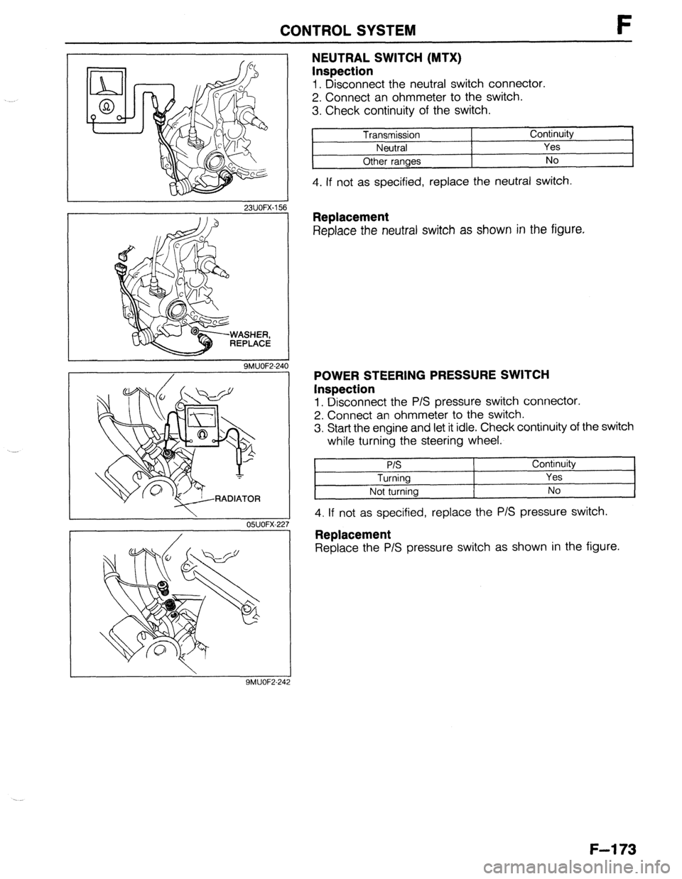
NEUTRAL SWITCH (MTX)
Inspection
1. Disconnect the neutral switch connector.
2. Connect an ohmmeter to the switch.
3. Check continuity of the switch.
Transmission Continuity
Neutral Yes
Other ranges No
4. If not as specified, replace the neutral switch.
Replacement
Replace the neutral switch as shown in the figure.
POWER STEERING PRESSURE SWITCH
Inspection
1. Disconnect the P/S pressure switch connector.
2. Connect an ohmmeter to the switch.
3. Start the engine and let it idle. Check continuity of the switch
while turning the steering wheel.
P/S
Turning
Not turning Continuity
Yes
No
4. If not as specified, replace the P/S pressure switch.
Replacement
Replace the P/S pressure switch as shown in the figure.
F-l 73
Page 625 of 1164

N
STEERING SYSTEM
INDEX ......................................................
MANUAL STEERING ............................... ;I g
ENGINE SPEED SENSING POWER
STEERING (ESPS) ................................. N- 3
OUTLINE ..................................................
SPECIFICATIONS .................................... ;I ::
MANUAL STEERING ..................................
PREPARATION ....................................... ;I ;
TROUBLESHOOTING GUIDE.. .................. N- 5
BOOT ................................................... N- 6
STEERING WHEEL AND COLUMN.. .......... N- 6
STEERING GEAR AND LINKAGE .............. N-13
ENGINE SPEED SENSING POWER
STEERING .............................................. N-23
PREPARATION ....................................... N-23
TROUBLESHOOTING GUIDE.. .................. N-25
AIR BLEEDING ....................................... N-26
STEERING WHEEL AND COLUMN.. .......... N-26
POWER STEERING FLUID.. ...................... N-27
STEERING GEAR AND LINKAGE .............. N-30
POWER STEERING OIL PUMP.. ................ N-37
DRIVE BELT ........................................... N-41
23UONX-001
Page 627 of 1164

INDEX
ENGINE SPEED SENSING POWER STEERING (ESPS)
FLUID
ATF M STEERING WHEEL PLAY
O-30mm (O-l .18 in)
SPECIFICATION
-IIt or Dexron@lI
I T nFFl FCTIC-IN
--. --w. .-.. NEW: 8.0-9.0mm (0.31-0.35 in)
USED: 9.0-lO.Omm (0.35-0.39 in)
LIMIT: 11.5mm (0.45 in)
23UONX-00
1. Boot
4. Drive belt
Removal / installation
.................. page N- 6 Inspection ................................... page N-41
2. Steering gear and linkage Adjustment .................................
page N-42
Removal / Installation.. ................ page N-30 Replacement .............................. page N-42
Disassembly / Inspection.. ..........
page N-31 5. Power steering fluid
Assembly..
.................................. page N-34 Air bleeding ................................ page N-26
3. Power steering oil pump Inspection.. .................................
page N-27
Removal I Installation
.................. page N-37 6. Steering wheel and column
Disassembly / Inspection I Inspection (On-vehicle).
.............. page N-26
Assembly ..................................
page N-38 Removal / Installation..
................ page N- 9
Disassembly / Assembly ............. page
N-l 0
Inspection ................................... page N-l 1
N-3
Page 628 of 1164

OUTLINE, MANUAL STEERING
OUTLINE
SPECIFICATIONS
Item
Steering wheel
Steering shaft and joint
Steering gear Outer diameter mm (in)
Lock-to-lock turns
Shaft
Joint
Power assist
Gear
Gear ratio
Rack stroke mm (in)
Power steering fluid
Fluid capacity liter (US qt, Imp qt) Manual steering Power steering 370 (14.6)
4.3 3.0
Collapsible
2cross joint
-
Engine speed sensing
Rack-and-pinion
a0 (infinite)
140 (5.51)
-
ATF Dexron@lI or M-III
-
0.8 (0.85, 0.70)
23UONX-00
MANUAL STEERING
PREPARATION
SST
49 0118 850C
Puller, ball joint For 49 1243 785
removal of tie rod
end Installer, dust
boot
49 0180 5108
Attachment,
steering worm
bearing preload
measuring For
measurement of
pinion preload 49 F032 308
Installer For
installation of dust
boot
For
installation of
oil seal
93GONX-OC
N-94