warning MAZDA PROTEGE 1992 Repair Manual
[x] Cancel search | Manufacturer: MAZDA, Model Year: 1992, Model line: PROTEGE, Model: MAZDA PROTEGE 1992Pages: 1164, PDF Size: 81.9 MB
Page 915 of 1164

WARNING SYSTEM
Light-off reminder alarm does not sound.
VB: Battery voltage
Terminal Connected to Test condition Specification To correct
C Headlight switch Headlight switch ON VB Check headlight switch and
wiring harness
(Refer to pages T-27, 28)
P Ignition switch Ignition switch ON VB Check ignition switch and
wiring harness
(Refer to page T-21)
N Door switch Any door open ov Check door switches and
All doors closed V0 wiring harness
(Refer to page T-51)
23UOTX-033
Seat belt alarm does not sound.
VB: Battery voltage
Terminal Connected to Test condition Specification To correct
P ignition switch Ignition switch ON
Vs Check ignition switch and
wiring harness
(Refer to page T-21)
D Seat belt buckle switch Seat belt buckled
00 Check seat belt buckle switch
Seat belt unbuckled
00 and wiring harness
(Refer to page S-102)
23UOTX-034
Seat belt timer does not operate.
VB: Battery voltage
Terminal Connected to Test condition Specification To correct
P Ignition switch Ignition switch ON VE Check ignition switch and
wiring harness
(Refer to page T-21)
23UOTX-035
Passive shoulder belt alarm does not sound.
VB: Battery voltage
Connected to Test condition
Ignition switch Ignition switch Specification
VB
Passive shoulder belt
control unit For 5 seconds after
ignition switch and belt
unbuckled
Other conditions 00
co
IG key illumination timer does not operate.
To correct
I
Check ignition switch and
wiring harness
(Refer to page T-21)
Check passive shoulder belt
control unit and wiring harness
(Refer to page S-104)
23UOTX-036
Ve: Battery voltage
Terminal Connected to Test condition Specification To correct
L IG key illumination Either door open
VB Check bulbs and wiring
harness
N Door switch Any door open ov Check door switches and
All doors closed
VB wiring harness
(Refer to page T-51)
23UOTX-037
T-59
Page 917 of 1164

WARNING SYSTEM T
13UOTX-07
63U15X-05
, I//
‘nF -
-
-
FUEL
13UOTX.08C
- CHARGE
13UOTX-08
13UOTX-08
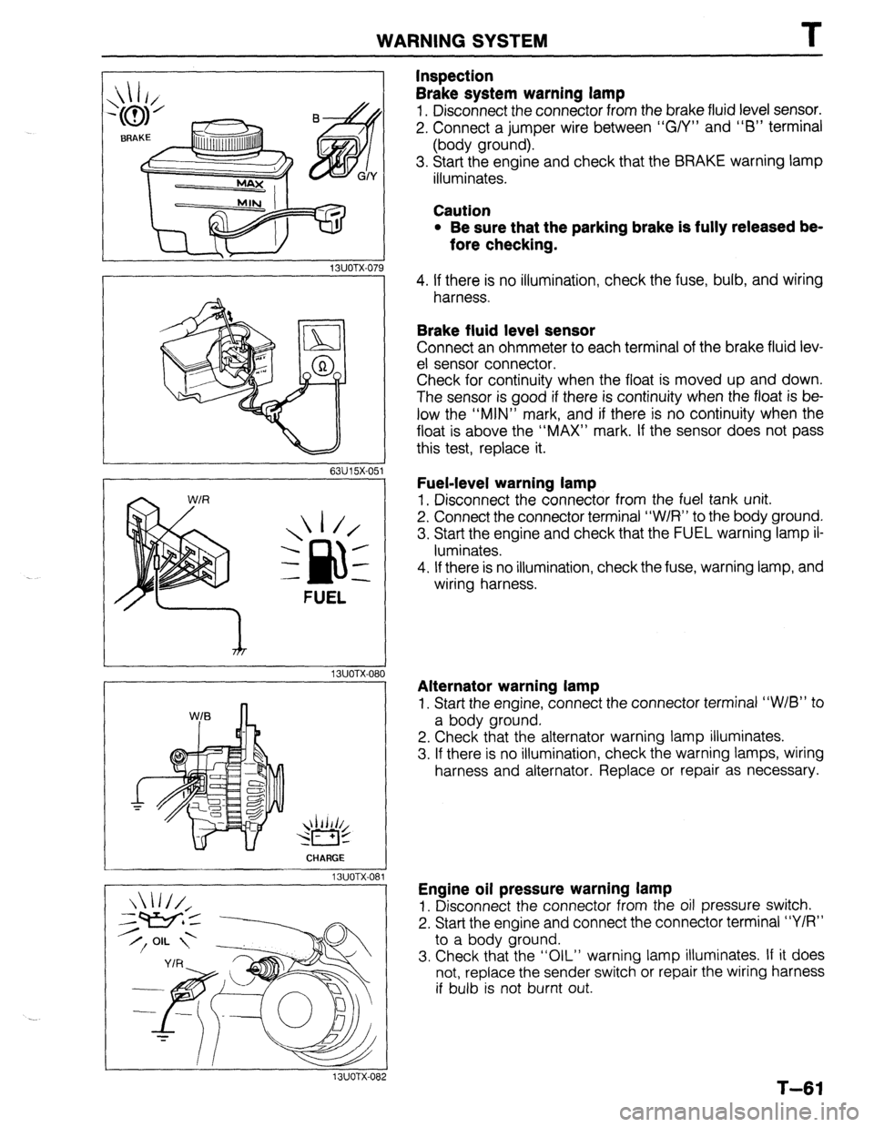
Inspection
Brake system warning lamp
1. Disconnect the connector from the brake fluid level sensor.
2. Connect a jumper wire between “G/Y” and “6” terminal
(body ground).
3. Start the engine and check that the BRAKE warning lamp
illuminates.
Caution
l Be sure that the parking brake is fully released be-
fore checking.
4. If there is no illumination, check the fuse, bulb, and wiring
harness.
Brake fluid level sensor
Connect an ohmmeter to each terminal of the brake fluid lev-
el sensor connector.
Check for continuity when the float is moved up and down.
The sensor is good if there is continuity when the float is be-
low the “MIN” mark, and if there is no continuity when the
float is above the “MAX” mark. If the sensor does not pass
this test, replace it.
Fuel-level warning lamp
1. Disconnect the connector from the fuel tank unit.
2. Connect the connector terminal “W/R” to the body ground.
3. Start the engine and check that the FUEL warning lamp il-
luminates.
4. If there is no illumination, check the fuse, warning lamp, and
wiring harness.
Alternator warning lamp
1. Start the engine, connect the connector terminal “W/B” to
a body ground.
2. Check that the alternator warning lamp illuminates.
3. If there is no illumination, check the warning lamps, wiring
harness and alternator. Replace or repair as necessary.
Engine oil pressure warning lamp
1. Disconnect the connector from the oil pressure switch.
2. Start the engine and connect the connector terminal “Y/R”
to a body ground.
3. Check that the “OIL” warning lamp illuminates. If it does
not, replace the sender switch or repair the wiring harness
if bulb is not burnt out.
T-61
Page 918 of 1164

T
I WARNING SYSTEM
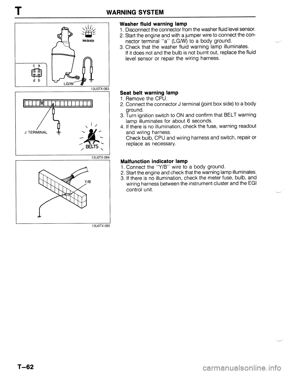
Washer fluid warning lamp
1. Disconnect the connector from the washer fluid level sensor.
2. Start the engine and with a jumper wire to connect the con-
nector terminal “a” (LGIW) to a body ground.
3. Check that the washer fluid warning lamp illuminates.
If it does not and the bulb is not burnt out, replace the fluid
level sensor or repair the wiring harness.
13UOTX-08
_-
1 /
J TERMINAL -
13UOTX-08
13UOTX-08
Seat belt warning lamp
1, Remove the CPU.
2. Connect the connector J terminal (joint box side) to a body
ground.
3. Turn ignition switch to ON and confirm that BELT warning
lamp illuminates for about 6 seconds.
4. If there is no illumination, check the fuse, warning readout
and wiring harness.
Check bulb, CPU and wiring harness and switch, repair or
replace as necessary.
Malfunction indicator lamp
1, Connect the “Y/B” wire to a body ground.
2. Start the engine and check that the warning lamp illuminates.
3. If there is no illumination, check the meter fuse, bulb, and
wiring harness between the instrument cluster and the EGI
control unit.
T-62
Page 919 of 1164

INSTRUMENT CLUSTER T
INSTRUMENT CLUSTER
PREPARATION
SST
I
I
49 0839 285
Checker, fuel
thermometer For
inspection of fuel
and water
temperature
gauge
I I
I
23UOTX-038
STRUCTURAL VIEW
WITH TACHOMETER (2WD)
WITHOUT TACHOMETER (2WD)
1. Speedometer 4. Fuel gauge
Troubleshooting . . . . . . . ..*................ page T-64 Troubleshooting . . . . . . . . . . . . . . . . . . . . . . . . . . page T-64
Inspection .,.......,,.......,,...,,.......... page T-71 Inspection . . . . . . . . . . . . . . . . . . . . . . . . . . . . . . . . . . . page T-71
2. Tachometer 5. Warning and indicator
Troubleshooting ..,....................... page T-64 Inspection ,.......,,......................... page T-61
inspection . . . . . . . . . . . . . . . . . . . . . . . . . . . . . . . . . . page T-71 6. Odometer
3. Water temperature gauge 7. Tripmeter
Troubleshooting . . . . . . . . . . . . . . . . . . . . . . . . . . page T-64
Inspection .,,........,,,,......,,............ page T-72
T-63
Page 973 of 1164

TROUBLESHOOTING GUIDE U
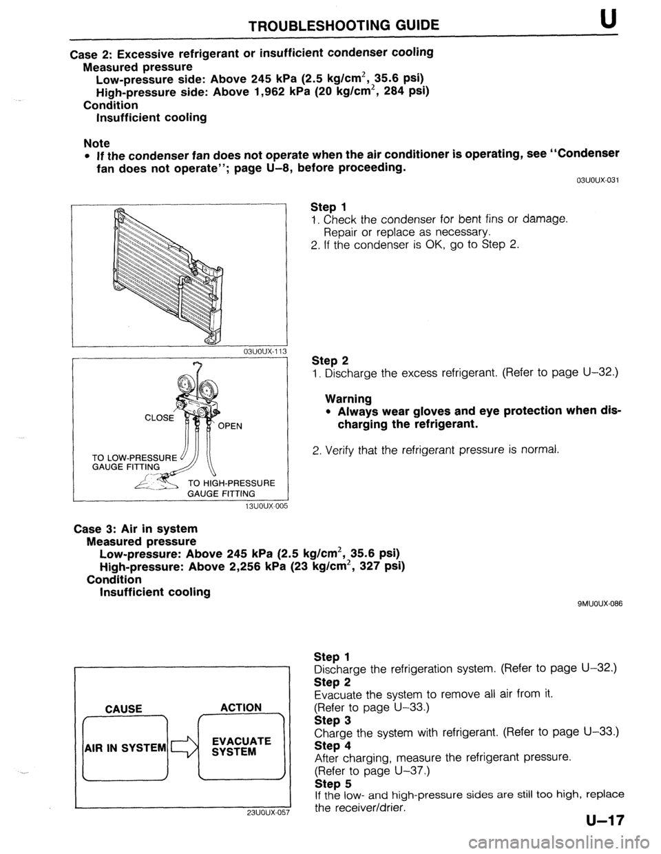
Case 2: Excessive refrigerant or insufficient condenser cooling
Measured pressure
Low-pressure side: Above 245 kPa (2.5 kg/cm2, 35.6 psi)
High-pressure side: Above 1,962 kPa (20 kg/cm2, 284 psi)
Condition
Insufficient cooling
Note
l If the condenser fan does not operate when the air conditioner is operating, see “Condenser
fan does not operate”; page U-8, before proceeding.
TO LOW
GAUGE
H-PRESSURE
GAUGE FITTING
13uoux-00 5 03uoux-031
Step 1
1. Check the condenser for bent fins or damage.
Repair or replace as necessary.
2. If the condenser is OK, go to Step 2.
Step 2
1. Discharge the excess refrigerant. (Refer to page U-32.)
Warning
l Always wear gloves and eye protection when dis-
charging the refrigerant.
2. Verify that the refrigerant pressure is normal.
Case 3: Air in system
Measured pressure
Low-pressure: Above 245 kPa (2.5 kg/cm2, 35.6 psi)
High-pressure: Above 2,256 kPa (23 kg/cm2, 327 psi)
Condition
Insufficient cooling
. . CAUSE ACTION
AIR IN SYSTEM EVACUATE
SYSTEM
9MUOUX-086
Step 1
Discharge the refrigeration system. (Refer to page U-32.)
Step 2
Evacuate the system to remove all air from it.
gFI;;r; page U-33.)
Charge the system with refrigerant. (Refer to page U-33.)
Step 4
After charging, measure the refrigerant pressure.
(Refer to page U-37.)
Step 5
If the low- and high-pressure sides are still too high, replace
I
23UOUX-057 the receiver/drier.
Page 1034 of 1164

TD TECHNICAL DATA
Coil Spring Specifications (See page R-5 for coil spring applications)
*’ Main identification mark color: Indicated on second coil from bottom. l * Auxiliary identification mark color: Indicated on third coil from bottom.
T. BODY ELECTRICAL SYSTEM
Item
Headlight
Frnnt tl wn sinnnl/Pnrkinn linht
Specification (W) (Bulb Trade number)
65145 (9004)
2718 II I 571
I
“‘VW, I u”“y’ 1. I” \’ ‘V’,
uinh mount stoplight 18.4 (1141)
turn single light 27 (1156)
Y-,-~p light 27 (1156)
Rear side marker light (Sedan) 3.8 (194)
License plate light 7.5 (89) [PROTEGE], 5 (168) [3HBl
Interior 10
Interior and spot lamp
spot 6
Interior lamp 10
‘i--” Spot lamp (in overhead console)
8 (67)
Cargo room lamp 5 (168)
Trunk room lamp 5 (168)
I I
ntminr Iamnc
I
Curtesy lamp
High beam
Turn light
Brake
Hold
) Charge 5 (168)
3.4
3.4
3
3 (158)
i
Oil pressure
Washer
Seat belt
Malfunction
Fuel
illumination 3 (158)
3 (158)
3 (158)
3 (158)
3 (158)
3 (158)
3.4 Indicator and
warning lamps
Check 3 (158)
Dif. lock
I 3 (158) .-
,
-.-’
I
I
TD-20
Page 1051 of 1164

PARTS
DIFFERENTIAL ..................................... Jl-52
SHIFT MECHANISM ............................. Jl-56
TRANSAXLE ............................................ Jl-8
TRANSAXLE OIL .................................... Jl-7
MANUAL TRANSAXLE (G5M-R) .................. J2-2
DIFFERENTIAL ..................................... J2-43
SHIFT MECHANISM ............................. J2-46
TRANSAXLE.. .......................................... J2-8
TRANSAXLE OIL .................................... J2-7
MOLDING, PROTECTOR, GARNISH ...........
S-42
BELTLINE MOLDING ............................. S-48
REAR WINDOW MOLDING.. ............. S-43,44
ROOF MOLDING.. .................................. S-46
SIDE PROTECTOR ................................. S-49
UPPER WINDSHIELD MOLDING,
A-PILLAR GARNISH ............................ S-42
NEUTRAL SWITCH (MTX) . . . . . . . . . . . . . . . . . . . . . . . . . . F-l 73
0
1
\_ OIL COOLER (ENGINE). ................................ D-8
OIL PAN (ENGINE) ........................................ D-9
OIL PUMP (ENGINE) ................................... D-l 3
..................................... F-l 71
OXYGEN SENSOR
P
PARKING BRAKE ......................................... P-31
PARKING BRAKE CABLE ............................ P-32
PARKING BRAKE LEVER ............................ P-33
PARKING BRAKE SHOE ............................. P-31
PASSIVE SHOULDER BELT SYSTEM.. ..... S-103
DOOR CATCH SWITCH ....................... S-l 07
LIMIT SWITCH ...................................... S-l 07
PASSIVE SHOULDER BELT MOTOR.. S-106
SPEED SENSOR ................................... S-l 07
WARNING SWITCH .............................. S-l 07
PCV VALVE ................................................
POWER BRAKE UNIT ‘;--=I;;
..................................
POWER DOOR LOCK SYSTEM ................... S-23
DOOR LOCK CONTROL.. ...................... S-26
DOOR LOCK SWITCH.. .......................... S-26
DOOR LOCK TIMER AND RELAY.. ....... S-26
POWER STEERING.. .................................... N-23
POWER STEERING FLUID .......................... N-27
POWER STEERING OIL PUMP.. ................. N-37
POWER STEERING PRESSURE SWITCH . . F-l 73
POWER WINDOW SYSTEM.. .......................
S-27
MAIN POWER WINDOW SWITCH.. .......
S-31
POWER WINDOW MOTOR.. ..................
S-32
POWER WINDOW SUB-SWITCH ........... S-32
PRESSURE REGULATOR (FUEL). ............. F-l 29 . . . . . . . . , . . . . . , . RADIATOR CAP .............................................
E-7
RADIATOR GRILLE,
I
LOWER GRILLE MOLDING ....................... S-51 fl
RADIATOR THERMOSWITCH ...................... E-17 t
REAR AXLE ................................................. M-10
REAR BRAKE (DISC) ................................... P-23
REAR BRAKE (DRUM) ................................. P-28
REAR BUMPER ............................................ s-40
REAR COMBINATION LIGHT.. ....
REAR CROSSMEMBER ............................... R-29
REAR DOOR ................................................ S-l 5
REAR DOOR LOCK AND OPENER.. .
REAR FINISHER ........................................... s-52
REAR HATCH ............................................... s-20
REAR HATCH LOCK AND OPENER.. ......... S-22
REAR SHOCK ABSORBER AND SPRING.. R-21
REAR SIDE MARKER LIGHT ....................... T-48
REAR SIDE WINDOW REGULATOR AND . . . . . . . . .
AI .,.n
INDEX
Q
QUARTER WINDOW GLASS . . . . . . . . . . . . ..a........ S-62
R
RADIATOR . . . . . . . . . . . . . . . . . . . . . . . . . . . . . . . . . . . . . . . . . . . . . . . . . . . . . .
kiLA33 ........................................................ a-- I I
REAR SPEAKER ........................................... T-99
REAR SPOILER ............................................ s-41
REAR STABILIZER.. ..................................... R-27
REAR SUSPENSION .................................... R-20
REAR WINDOW GLASS ............................... S-63
REAR WINDOW DEFROSTER.. .................... T-74
REAR WINDOW DEFROSTER SWITCH ....... T-77
REAR WIPER AND WASHER ...................... S-74
REAR WASHER MOTOF
REAR WIPER AND WASHER SWITCH . . S-77
REAR WIPER MOTOR ............................ s-77
RELEASE BEARING (CLUTCH). . . . . . . . . . ..s..... H-17 I . . . . . . . . ...*. .*......*..
SEAT BELT.. ........................................ S-100,102
BUCKLE SWITCH.. ............................... S-l 02
SEAT ........................................................... s-110
SEPARATOR (FUEL) .................................. F-l 40
SHUTTER VALVE ACTUATOR (VICS) ........ F-l 18
SLIDING SUNROOF ..................................... S-80
MOTOR ASSEMBLY ............................... S-81
SUNROOF RELAY.. ................................ S-82
SUNROOF SWITCH.. .............................. S-82
SOLENOID VALVE
(PRESSURE REGULATOR CONTROL) .... F-135
SOLENOID VALVE (PURGE CONTROL). .. F-140
SOLENOID VALVE (VICS) .......................... F-l 18
SPARK PLUGS ............................................ G-18
-II__
Page 1055 of 1164

Z
SYSTEM INDEX
System Section System Section
AUDIO SYSTEM ......................................................... J
BACK-UP LIGHTS ...................................................
F-3
CHARGING SYSTEM ............................................... A-2
CIGARETTE LIGHTER ............................................... I-1
COMMON CONNECTOR LIST ..................................... X
COOLING FAN SYSTEM ....................................... B-3.4
COURTESY LAMPS .................................................. l-3
CRUISE CONTROL SYSTEM ...................................... Q
DAYTIME RUNNING UGHTS .................................... E-3
DIAGNOSIS CONNECTOR .......................................... U
DIGITAL CLOCK ....................................................... l-l
ELECTRICAL WIRING SCHEMATIC ............................. W
ENGINE CONTROL SYSTEM (MT) ................. B-l a, 1 b, 1 c
ENGINE 8 EC-AT CONTROL
SYSTEM (EC-AT) ...................................... B-2a,2b,2c
GENERAL INFORMATION .......................................... GI
GROUND POINT ........................................................ Y
HEADLIGHTS ....................................................... E-l ,2
HEATER 8 AIR CONDITIONER .................................... G
HORN .................................................................... F-3
IGNITION KEY CYLINDER LAMP ............................... l-2
ILLUMINATION LAMPS .............................................
l-4
INSTRUMENT CLUSTER . WARNING LAMPS .............. C INTER CONNECTING OF JOINT BOX ......................... JB
INTERIOR LAMP ...................................................... l-2
JOINT BOX .............................................................. JB
LICENSE PLATE UGHTS ......................................... E-4
PARTS INDEX ........................................................... PI
PARTS LOCATION ................................................... PL
PASSIVE SHOULDER BELT CONTROL SYSTEM .......... S
POSITION LIGHTS ................................................... E-4
POWER DOOR LOCK ............................................. K-2
POWER OUTSIDE MIRROR ......................................... L
POWER WINDOW ................................................... K-l
REAR SIDE MARKER LIGHTS.. ................................. E-4
REAR WINDOW DEFROSTER .................................... I-1
REAR WIPER 8 WASHER ........................................ D-3
SHIFT-LOCK SYSTEM ................................................ H
SLIDING SUNROOF ................................................... M
SOUND WARNING SYSTEM ...................................... l-2
STARTING SYSTEM ................................................ A-l
STOPLIGHTS .......................................................... F-2
TAILLIGHTS ............................................................ E-4
TRUNK COMPARTMENT LAMP ................................. l-3
TURN 8 HAZARD FLASHER UGHTS ......................... F-l
WINDSHIELD WIPER 8 WASHER .......................... D-l ,2
Page 1077 of 1164

WIRINQ DIAQRAM 2
-CURRENT FROM BATTERY
W II f”‘l FCTRICAL WIRING SCHEMATIC _1_=;!:: %% :% I’*
BATTERY
P-
f
30A HEAD SYSTEM NAME
-a
c------
15A TAIL I
t-
BOA
MAIN
7 ST /;
(i
IG
:
:
1
:
I
20A ?--
AD FAN
_-. --
VW/B : I
I
I
I TRUNK COMPARTMENT
l LAMP I-3
:
I ( - n COURTESY LAMPS I-3
I
1OA
3EAR WIPER I
-- ---- L,G--/-~~-.=/zzI~~~
l REAR WIPER 6 WASHER D-3
20A WIPER
30A HEATER
,-w ---- L,w-l;c::::
I
INSTRUMENT CLUSTER
l & WARNING LAMPS C
15A METER
-----+yy _---
IOA ROOM
-1
t
----------.mBUCK-UP LIGHTS F-3
20A STOP
-G/W i - m HORN F-3
1
I
F-2
/--------%CRUISE CONTROL SYSTEM 0
. l SHIFT-LOCK SYSTEM
15A
HAZARD
I-- ------. H
--- _------
TURN 6 HAZARD
--o----B/R ; n FLASHER LIGHTS F-l
I
IPOWER DOOR LOCK K-;
’ PASSIVE SHOULDER BELT s
-mCONTROL SYSTEM
+-B/R--+-/ “Yr. I YV.LI, T.AI1a.A
---------B/W----~-i-t------. n P,-&,ER WINDOW
K-l
I
1
I I 15A ENGINE
- - I
:-,-..-L ----.- T -------- B,wl--‘-
; 30A FUEL INJ ’ a...
I- W/G ’ --------.=ENGINE CONTROL SYSTEM y-2
t ----------e--e-_ I--- ---_ .w-.w-.m-.
I
I t
: I 0
WDIGITAL CLOCK I-l
,
I 20A DEFOG I r-- WINDOW DEFROSTER 1-1
B/L I -- mCIGARETTE LIGHTER I-l
:
_ mAU’)IO SYSTEM
i----a,w-.--15A RAo1o -.-L,e-i~---i--mPOWER J
OUTSIDE MIRRIOR L
30A COOLING FAN L- ------------.
l COOLING FAN SYSTEM ;-4
B/R-p-
l STARTING SYSTEM A-l
Page 1102 of 1164

j Z WlRiNQ MAQRAM A.. .EC-AT 0 .CANACA
/
l NSTRUMENT CLUSTER & WARNING LAMPS *...WITH PASSIVE SHOULDER BELT
c
BATTERY
0 01 MAIN
BOA
0 0, B (E)
0 (F)
.-I
FLASHER UNIT
SECTION F-l
(SECTION E-3) HEADLIGHTS
(SECTION E-2) INSTRUMENT CLUSTER
ILLUMINATION LAMP
;REFER TO SECTION I-4
k,
JR-06 @
METER
15A
STARTING SYSTEM
(SECTION n-i)
E J&O4 0
WY
Fl
I
INSTRUMENT CLUSTER
OOHC SEYSOR
&
:-04 PARKING BRAKE C-07 WATER THERMOSENSOR
SWITCH (I?) (EMI
(INJI
DOHC