engine coolant MAZDA PROTEGE 1992 Service Manual
[x] Cancel search | Manufacturer: MAZDA, Model Year: 1992, Model line: PROTEGE, Model: MAZDA PROTEGE 1992Pages: 1164, PDF Size: 81.9 MB
Page 302 of 1164
F TROUBLESHOOTING GUIDE
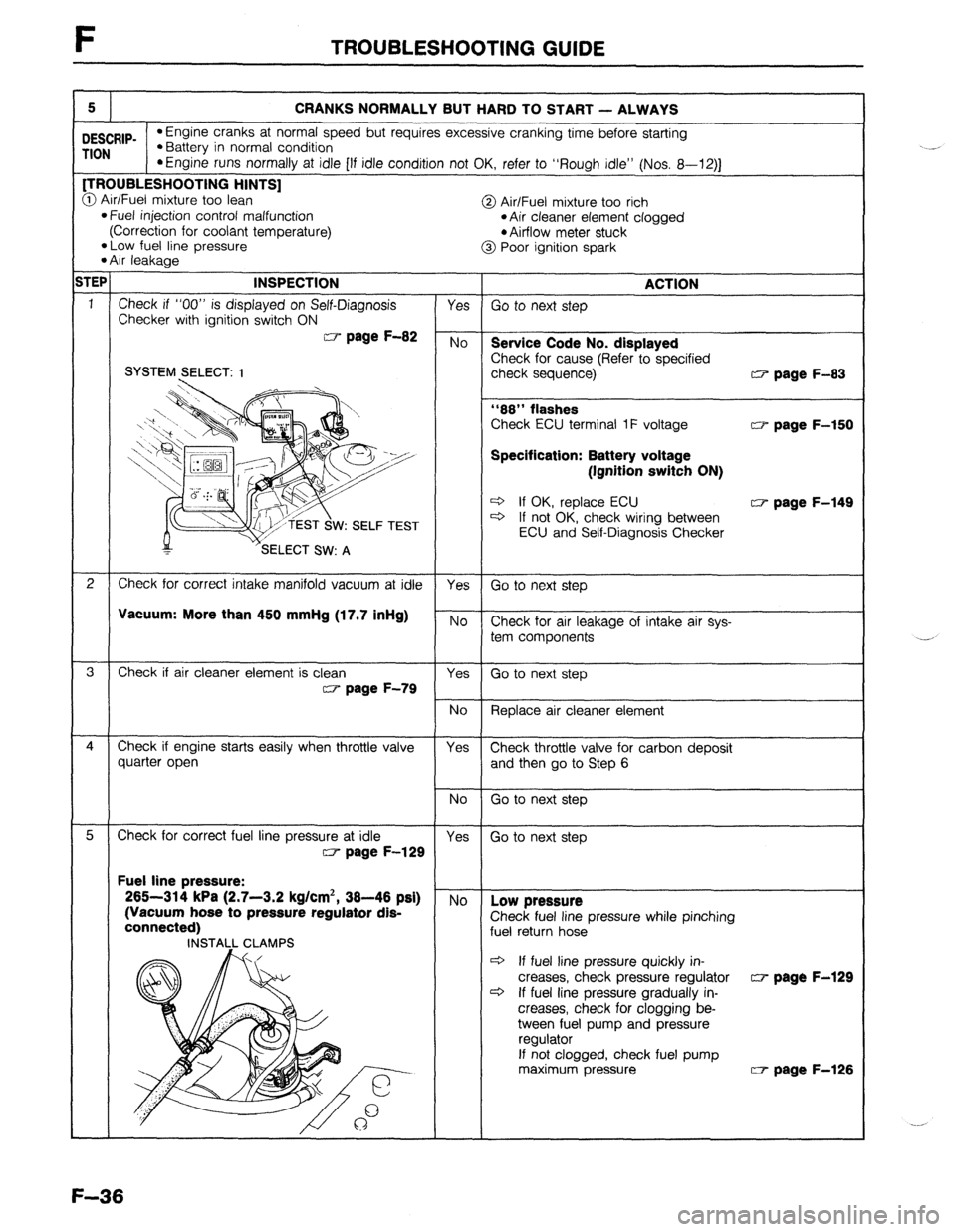
5
CRANKS NORMALLY BUT HARD TO START - ALWAYS
DESCRIP- l Engine cranks at normal speed but requires excessive cranking time before starting
TION l Battery in normal condition
*Engine runs normally at idle [If idle condition not OK, refer to “Rough idle” (Nos. 8-12)J [TROUBLESHOOTING HINTS]
@ Air/Fuel mixture too lean
@ Air/Fuel mixture too rich l Fuel injection control malfunction
(Correction for coolant temperature) *Air cleaner element clogged
l Airflow meter stuck
*Low fuel line pressure
l Air leakage @ Poor ignition spark
;TEP INSPECTION ACTION
1
Check if “00” is displayed on Self-Diagnosis Yes Go to next step
Checker with ignition switch ON W page F-82 No
Service Code No. displayed
Check for cause (Refer to specified SYSTEM SELECT: 1 check sequence) w page F-83
“88” flashes
Check ECU terminal 1F voltage w page F-150
Specification: Battery voltage
(Ignitlon switch ON)
* If OK, replace ECU w page F-149
W: SELF TEST c3 If not OK, check wiring between
ECU and Self-Diagnosis Checker
2 Check for correct intake manifold vacuum at idle
Yes Go to next step
VsCUUm: More than 450 mmHg (17.7 inHg) No Check for air leakage of intake air sys-
tem components
3 Check if air cleaner element is clean
Yes Go to next step w page F-79
No
Replace air cleaner element
4 Check if engine starts easily when throttle valve Yes Check throttle valve for carbon deposit
quarter open and then go to Step 6 Fuel line pressure:
265-314 kPa (2.7-3.2 kg/cm*, 38-46 psi)
(Vacuum hose to pressure regulator dis-
pressure while pinching
c3 If fuel line pressure quickly in-
creases, check pressure regulator w page F-129
c3 If fuel line pressure gradually in-
creases, check for clogging be-
tween fuel pump and pressure
If not clogged, check fuel pump
maximum pressure W- page F-126
F-36
Page 304 of 1164
F TROUBLESHOOTING GUIDE
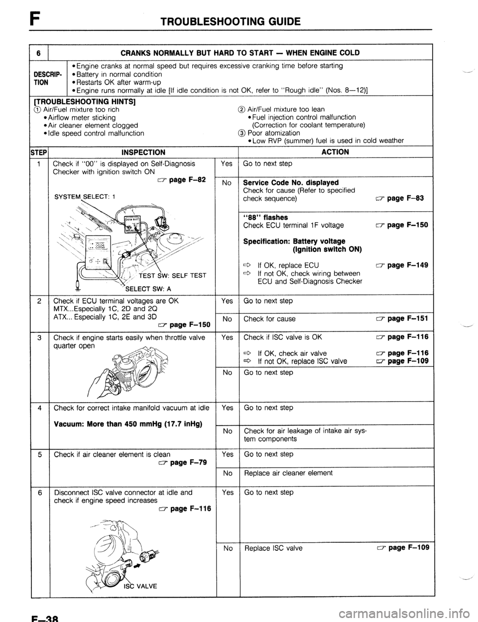
6 CRANKS NORMALLY BUT HARD TO START - WHEN ENGINE COLD
l Engine cranks at normal speed but requires excessive cranking time before starting )ESCRIP-
l Battery in normal condition UON
*Restarts OK after warm-up
*Engine runs normally at idle [If idle condition is not OK, refer to “Rough idle” (NOS. 8-124 [TROUBLESHOOTING HINTS]
3 Air/Fuel mixture too rich
@ Air/Fuel mixture too lean l Airflow meter sticking l Fuel injection control malfunction
*Air cleaner element clogged
(Correction for coolant temperature)
l Idle speed control malfunction
@ Poor atomization
*Low RVP (summer) fuel is used in cold weather
SYSTEM SELECT: 1
Check ECU terminal 1 F voltage CT- page F-150
Specification: Battery voltage
(Ignition switch ON)
c3 If OK, replace ECU CT page F-149 c3 If not OK, check wiring between
ECU and Self-Diagnosis Checker Vacuum: More than 450 mmHg (17.7 inHg)
.
No
Check for air leakage of intake air sys-
tem components
5 Check if air cleaner element is clean Yes
Go to next step
~7 page F-79
No
Replace air cleaner element
6 Disconnect ISC valve connector at idle and
Yes Go to next step
check if engine speed increases CT page F-l 16
No
Replace ISC valve CT page F-109
--’
F-38
Page 310 of 1164

F TROUBLESHOOTING GUIDE
9
ROUGH IDLE/ENGINE STALLS AT IDLE - BEFORE WARM-UP
DESCRIP-
*Engine speed low or engine stalls or vibrates excessively at idle during warm-up
TION
[TROUBLESHOOTING HINTS]
@ Low intake air amount
@ Low fuel injection control
l Airflow meter stuck
*Fuel injection control malfunction
*Air cleaner element clogged
(Correction for coolant temperature)
*Air valve
@ Poor atomization
*Low RVP (summer) fuel used in cold weather
w page F-83
W: SELF TEST Check ECU terminal 1F voltage
w page F-150
Specification: Battery voltage
(Ignition switch ON)
c3 If OK, replace ECU c3 page F-149
* If not OK, check wiring between
ECU and Self-Diagnosis Checker
Vacuum: More than 450 mmHg (17.7 inHg)
AX.. Especially 2B, 2E and 30
w page F-150
NO Check for cause CT page F-181
5 Disconnect ISC valve connector and check if en-
Yes Go to next step
gine speed increases after warm-up
CT page F-l 18
No Replace ISC valve c3 page F-109
F-44
Page 311 of 1164
TROUBLESHOOTING GUIDE F
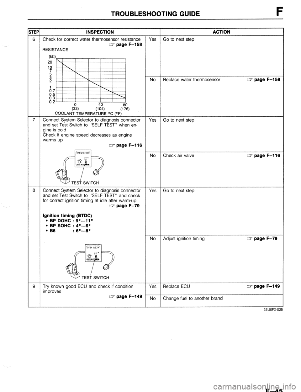
s TEP INSPECTION ACTION
6 Check for correct water thermosensor resistance
Yes Go to next step
w page F-158
RESISTANCE
WI
20
‘70
I No Replace water thermosensor w page F-158
A.7
0.5
lE 41
(1400,
(1%) COOLANT TEMPERATURE OC (OF)
Connect System Selector to diagnosis connector
Check if engine speed decreases as engine
Ignition timing (BTDC)
l BP DOHC : go-11 * l BP SOHC : 4*-6O
23UOFX-OS
F-45
Page 312 of 1164

F TROUBLESHOOTING GUIDE
10
ROUGH IDLE/ENGINE STALLS AT IDLE - AFTER WARM-UP
DESCRIP-
rlON
*Engine runs normally at idle during warm-up but engine stalls or vibrates excessively after warm-up [TROUBLESHOOTING HINTS]
3 Idle speed control system malfunction @ Air/Fuel mixture too rich
3 Air/Fuel mixture too lean l Fuel injection control malfunction l Air leakage (Correction for coolant temperature)
*Low fuel line pressure @ Poor ignition
@ Low engine compression CT= page F-83
Check ECU terminal 1F voltage CT page F-150
Specification: Battery voltage
(Ignition switch ON)
* If OK, replace ECU w page F-149 * If not OK, check wiring between
ECU and Self-Diagnosis Checker
Check for cause LY page F-151
Vacuum: More than 450 mmHg (17.7 inHg)
I.:.F page F-109
F-46
Page 316 of 1164
![MAZDA PROTEGE 1992 Service Manual F TROUBLESHOOTING GUIDE
13 HIGH IDLE SPEED AFTER WARM-UP
DESCRIP- l Idle speed excessive after warm-up
TION [TROUBLESHOOTING HINTS]
Excessive intake air supplied to engine
@I Throttle valve not f MAZDA PROTEGE 1992 Service Manual F TROUBLESHOOTING GUIDE
13 HIGH IDLE SPEED AFTER WARM-UP
DESCRIP- l Idle speed excessive after warm-up
TION [TROUBLESHOOTING HINTS]
Excessive intake air supplied to engine
@I Throttle valve not f](/img/28/57077/w960_57077-315.png)
F TROUBLESHOOTING GUIDE
13 HIGH IDLE SPEED AFTER WARM-UP
DESCRIP- l Idle speed excessive after warm-up
TION [TROUBLESHOOTING HINTS]
Excessive intake air supplied to engine
@I Throttle valve not fully closed
@ Idle speed control malfunction
l Air valve not closed l ISC valve stuck
l ISC valve connector disconnected l A/C, P/S, or E/L signal sent to ECU l Incorrect coolant temperature signal
stalled and operates freely w page F-l 14
@ If OK, go to Step 2
+ If not OK, clean, adjust or replace w page F-l 14
* If contaminated, clean throttle body Dashpot set speed: + If not contaminated, replace throttle
..*.............*..,........,... Approx. 3,000 rpm w page F-109
BP SOHC . . . . . . . . . . . . . . . . . . . . . . Approx. 2,700 rpm
BP DOHC . . . . . . . . . . . . . . . . . . . . . . Approx. 3,500 rpm
w page F-83
Check ECU terminal 1F voltage w page F-150
Specification: Battery voltage
(Ignition switch ON)
e If OK, replace ECU w page F-149
c3 If not OK, check wiring between
ECU and Self-Diagnosis Checker
Check for cause (Refer to specified
check sequence) w page F-108
W: SELF TEST
and Self-Diagnosis Checker
F-50
Page 344 of 1164

F ENGINE TUNE-UP
ENGINE TUNE-UP
PREPARATlON
SST
I
I I
49 BO19 9AO
System Selector For
inspection of igni-
tion timing and
idle speed
hA ‘I
03UOFX-04
03UOFX-04
03UOFX-04
NG POINT
03UOFX-04 03UOFX-045
BASIC INSPECTION
Engine Oil
1. Remove the engine oil level gauge and check the engine
oil level and oil condition.
2. Add or change the oil as necessary.
Coolant
Warning
l Never remove the radiator cap while the engine is
hot.
l Wrap a thick cloth around the cap before carefully
removing it.
1. Remove the coolant level gauge from the coolant reservoir.
2. Check that the coolant level is between the L and F marks
of the gauge.
3. Add coolant if necessary.
Battery
1. Check for corrosion on the terminals and for loose cable
connections. If necessary, clean the clamps and tighten
them firmly.
2. Check that the electrolyte level is between the UPPER LEV-
EL and LOWER LEVEL marks.
3. Add distilled water if necessary.
4. Check the specific gravity with a hydrometer.
Gravity: 1.27-l .29 (at 20% [68OF] )
Page 379 of 1164
INTAKE AIR SYSTEM F
I 23UOFX-096
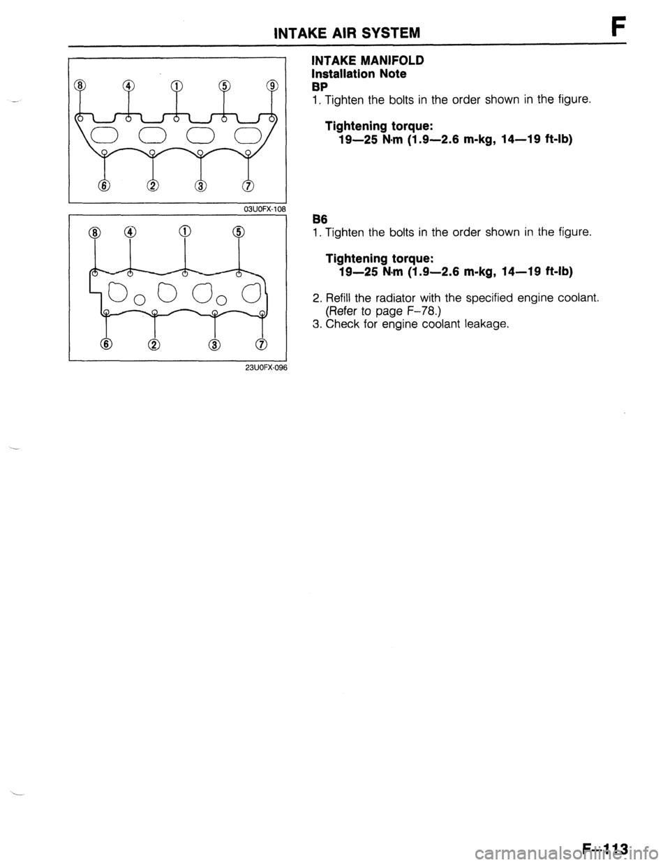
INTAKE MANIFOLD
Installation Note
BP
1, Tighten the bolts in the order shown in the figure.
Tightening torque:
19-25 N-m (1.9-2.6 m-kg, 14-19 ft-lb)
B6
1. Tighten the bolts in the order shown in the figure.
Tightening torque:
19-25 N-m (1.9-2.6 m-kg, 14-19 ft-lb)
2. Refill the radiator with the specified engine coolant.
(Refer to page F-78.)
3. Check for engine coolant leakage.
F-113
Page 382 of 1164
F IDLE SPEED CONTROL (ISC) SYSTEM
PREPARATION
SST
OBUOFX-113
OSUOFX-I 14
I
23UOFX-095
J 03UOFX-1 lf
23UOFX-101
F-116
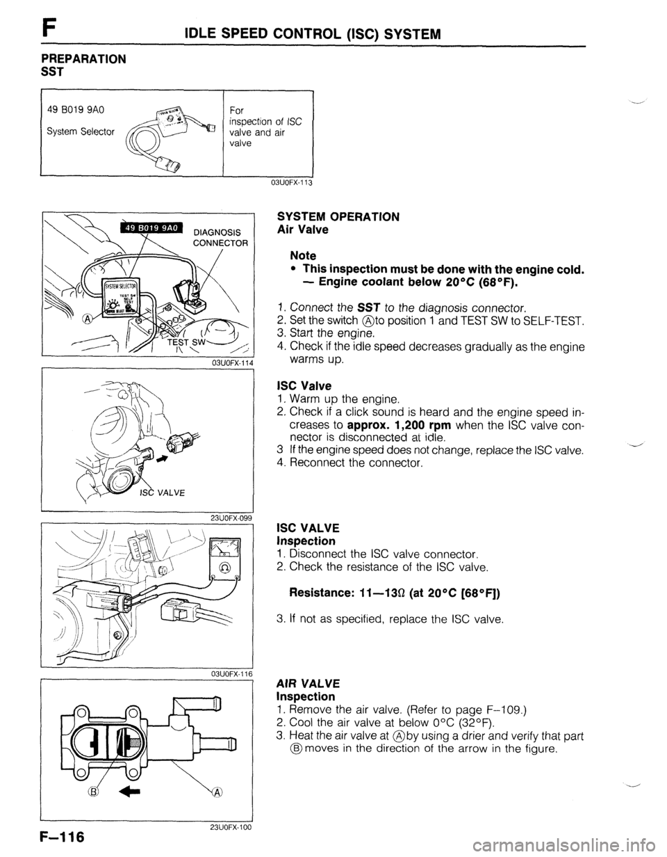
SYSTEM OPERATION
Air Valve
Note
l This inspection must be done with the engine cold.
- Engine coolant below 20°C (68°F).
1. Connect the SST to the diagnosis connector.
2. Set the switch @to position 1 and TEST SW to SELF-TEST.
3. Start the engine.
4. Check if the idle speed decreases gradually as the engine
warms up.
ISC Valve
1. Warm up the engine.
2. Check if a click sound is heard and the engine speed in-
creases to approx. 1,200 rpm when the ISC valve con-
nector is disconnected at idle.
3 If the engine speed does not change, replace the ISC valve.
4. Reconnect the connector.
ISC VALVE
Inspection
1. Disconnect the ISC valve connector.
2. Check the resistance of the ISC valve.
Resistance: 11-130 (at 20°C [68*F])
3. If not as specified, replace the ISC valve.
AIR VALVE
Inspection
1. Remove the air valve. (Refer to page F-109.)
2. Cool the air valve at below O°C (32OF).
3. Heat the air valve at @by using a drier and verify that part
@moves in the direction of the arrow in the figure.
Page 400 of 1164
F PRESSURE REGULATOR CONTROL SYSTEM
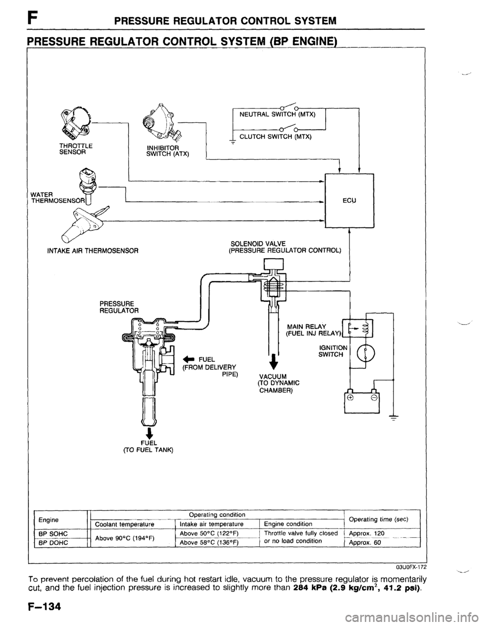
PRESSURE REGULATOR CONTROL SYSTEM (BP ENGINE)
THERMOSEN
SOLENOID VALVE
(PRESSURE REGULATOR CONTROL)
(FROM DELIVERY
FUEL
(TO FUEL TANK)
Engine
BP SOHC
BP DOHC Coolant temperature
Above 90% (194*F) Operating condition
Intake air temperature
Above 50°C (122OF)
Above 58OC (136OF) Engine condition . Operating time (set)
Throttle valve fully closed
Approx. 120
or no load condition
Approx. 60
#.nr IAt-%/ 4 7
To prevent percolation of the fuel during hot restart idle, vacuum to the pressure regulator is momentarily
cut, and the fuel injection pressure is increased to slightly more than 284 kPa (2.9 kg/cm2, 41.2 psi).
F-l 34