F-149 MAZDA PROTEGE 1992 Workshop Manual
[x] Cancel search | Manufacturer: MAZDA, Model Year: 1992, Model line: PROTEGE, Model: MAZDA PROTEGE 1992Pages: 1164, PDF Size: 81.9 MB
Page 267 of 1164
F
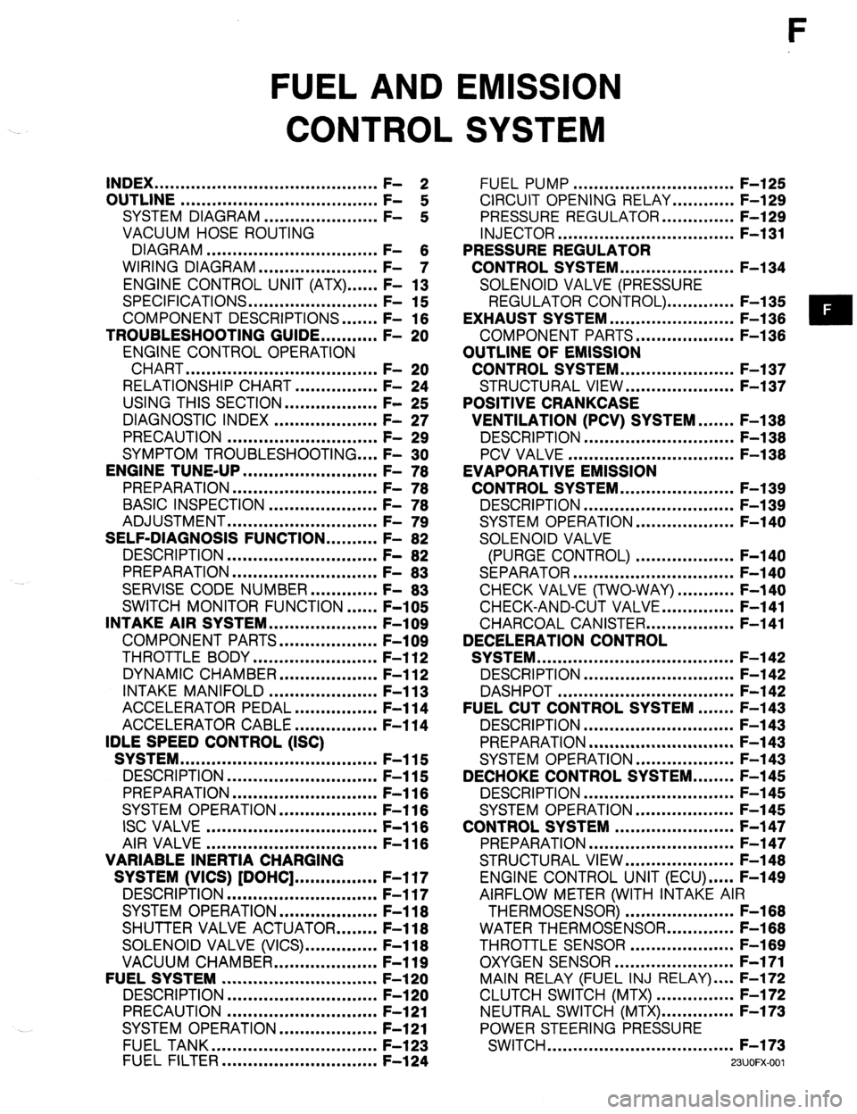
FUEL AND EMISSION
CONTROL SYSTEM
INDEX ...........................................
OUTLINE ...................................... ;: 2
SYSTEM DIAGRAM ...................... F-
:
VACUUM HOSE ROUTING
DIAGRAM .................................
WIRING DIAGRAM ....................... F- 6
- 7
ENGINE CONTROL UNIT (ATX) ...... F- 13
SPECIFICATIONS.. ....................... F- 15
COMPONENT DESCRIPTIONS.
...... F- 16
TROUBLESHOOTING GUIDE.. ......... F- 20
ENGINE CONTROL OPERATION
CHART
..................................... F- 20
RELATIONSHIP CHART.. .............. F- 24
USING THIS SECTION .................. F- 25
DIAGNOSTIC INDEX .................... F- 27
PRECAUTION ............................. F- 29
SYMPTOM TROUBLESHOOTING .... F- 30
ENGINE TUNE-UP
.......................... F- 76
PREPARATION ............................
F- 76
BASIC INSPECTION ..................... F- 78
ADJUSTMENT .............................
F- 79
SELF-DIAGNOSIS FUNCTION .......... F- 82
DESCRIPTION .............................
F- 82
PREPARATION
............................
F- 83
SERVISE CODE NUMBER.. ........... F- 83
SWITCH MONITOR FUNCTION ...... F-105
INTAKE AIR SYSTEM.. ................... F-109
COMPONENT PARTS.. ................. F-109
THROTTLE BODY ........................ F-l 12
DYNAMIC CHAMBER ................... F-l 12
INTAKE MANIFOLD ..................... F-l 13
ACCELERATOR PEDAL ................ F-l 14
ACCELERATOR CABLE ................ F-l 14
IDLE SPEED CONTROL (ISC)
SYSTEM ......................................
F-115
DESCRIPTION ............................. F-115
PREPARATION
............................ F-116
SYSTEM OPERATION.. ................. F-l 16
ISC VALVE ................................. F-116
AIR VALVE
................................. F-116
VARIABLE INERTIA CHARGING
SYSTEM (VICS) [DOHC] ................ F-l 17
DESCRIPTION ............................. F-117
SYSTEM OPERATION ................... F-l 18
SHUTTER VALVE ACTUATOR.. ...... F-l 18
SOLENOID VALVE (VICS). ............. F-118
VACUUM CHAMBER.. .................. F-119
FUELSYSTEM .............................. F-l 20
DESCRIPTION
............................. F-l 20
PRECAUTION ............................. F-121
SYSTEM OPERATION.. ................. F-121
FUEL TANK ................................
F-l 23
FUEL FILTER .............................. F-l 24 FUEL PUMP ............................... F-l 25
CIRCUIT OPENING RELAY.. .......... F-129
PRESSURE REGULATOR.. ............ F-129
INJECTOR .................................. F-l 31
PRESSURE REGULATOR
CONTROL SYSTEM.. .................... F-l 34
SOLENOID VALVE (PRESSURE
REGULATOR CONTROL). ............ F-l 35
EXHAUST SYSTEM ........................ F-l 36
COMPONENT PARTS.. ................. F-136
OUTLINE OF EMISSION
CONTROL SYSTEM.. .................... F-l 37
STRUCTURAL VIEW.. ................... F-l 37
POSITIVE CRANKCASE
VENTILATION (PCV) SYSTEM.. ..... F-138
DESCRIPTION .............................
F-l 38
PCV VALVE ................................ F-l 38
EVAPORATIVE EMISSION
CONTROL SYSTEM.. .................... F-l 39
DESCRIPTION ............................. F-l 39
SYSTEM OPERATION.. ................. F-140
SOLENOID VALVE
(PURGE CONTROL) ................... F-140
SEPARATOR ............................... F-l 40
CHECK VALVE (TWO-WAY) ........... F-140
CHECK-AND-CUT VALVE.. ............ F-141
CHARCOAL CANISTER.. ............... F-141
DECELERATION CONTROL
SYSTEM ...................................... F-l 42
DESCRIPTION ............................. F-l 42
DASHPOT .................................. F-142
FUEL CUT CONTROL SYSTEM ....... F-143
DESCRIPTION ............................. F-l 43
PREPARATION ............................ F-l 43
SYSTEM OPERATION.. ................. F-143
DECHOKE CONTROL SYSTEM.. ...... F-145
DESCRIPTION ............................. F-l 45
SYSTEM OPERATION ................... F-l 45
CONTROL SYSTEM ....................... F-l 47
PREPARATION ............................ F-147
STRUCTURAL VIEW.. ................... F-l 48
ENGINE CONTROL UNIT (ECU) ..... F-149
AIRFLOW METER (WITH INTAKE AIR
THERMOSENSOR) ..................... F-168
WATER THERMOSENSOR.. ........... F-168
THROTTLE SENSOR .................... F-l 69
OXYGEN SENSOR.. ..................... F-171
MAIN RELAY (FUEL INJ RELAY) .... F-172
CLUTCH SWITCH (MTX) ............... F-172
NEUTRAL SWITCH (MTX). ............. F-173
POWER STEERING PRESSURE
SWITCH .................................... F-173
WJOFX-001
Page 269 of 1164

INDEX F
1. Resonance duct
Inspection / Replacement.. ........ page F-l 09
2. Air cleaner element
Inspection ................................. page F- 79
Replacement.. ........................... page F-l 09
3. Airflow meter
(With intake air thermosensor)
Inspection
................................. page F-l 68
Replacement.. ........................... page F-l 09
4. Resonance chamber
Inspection I Replacement.. ........ page F-l 09
5. Throttle body
Inspection .................................
page F-l 12
Replacement.. ...........................
page F-l 09
6. Throttle sensor
inspection ................................. page F-l 69
Adjustment..
.............................. page F-l 69
Replacement.. ........................... page F-l 71
7. ISC valve
Inspection ................................. page F-l 16
Replacement..
........................... page F-l 09
8. Dashpot
Inspection ................................. page F-l 42
9. Dynamic chamber
Removal / Installation ................
page F-109
Inspection [DOHC] ................... page F-l 12
10. Air valve
Inspection
................................. page F-l 16
Removal / Installation ................ page F-109
11. Shutter valve actuator
Inspection ................................. page F-l 18
12. Vacuum chamber [DOHC]
Inspection ................................. page F-l 19
13. Intake manifold
Removal / Installation ................ page F-l 09
14. Injector
Inspection .................................
page F-l 31
Removal .................................... page F-131
Installation.. ............................... page F-l 33 15. Pressure regulator
Inspection ................................. page F-l 29
Replacement ............................. page F-l 30
16. Solenoid valve (Pressure regulator control)
[BP1
Inspection ................................. page F-l 35
17. Solenoid valve (VICS) [DOHC]
Inspection ................................. page F-l 18
18. Charcoal canister
Inspection ................................. page F-l 41
19. Solenoid valve (Purge control)
Inspection ................................. page F-l 40
20. Circuit opening relay
Inspection ................................. page F-l 29
Replacement ............................. page F-l 29
21. Engine control unit (ECU)
Removal / Installation ................ page F-l 49
Inspection ................................. page F-149
22. Clutch switch (MTX)
Inspection ................................. page F-l 72
Replacement.. ........................... page F-l 72
23. PCV valve
Inspection ................................. page F-l 38
24. Water thermosensor
Removal / Inspection /
Installation ............................... page F-l 68
25. Fuel filter (High-pressure side)
Replacement.. ........................... page F-l 24
26. Main relay (FUEL INJ relay)
Inspection ................................. page F-l 72
27. Neutral switch (MTX)
inspection ................................. page F-l 73
Replacement.. ........................... page F-l 73
28. Oxygen sensor
Inspection ................................. page F-l 71
Replacement ............................. page F-l 72
29. Power steering pressure switch
Inspection ................................. page F-l 73
Replacement.. ........................... page F-l 73
23UOFX-002
F-3
Page 296 of 1164
F TROUBLESHOOTING GUIDE
SYMPTOM TROUBLESHOOTING
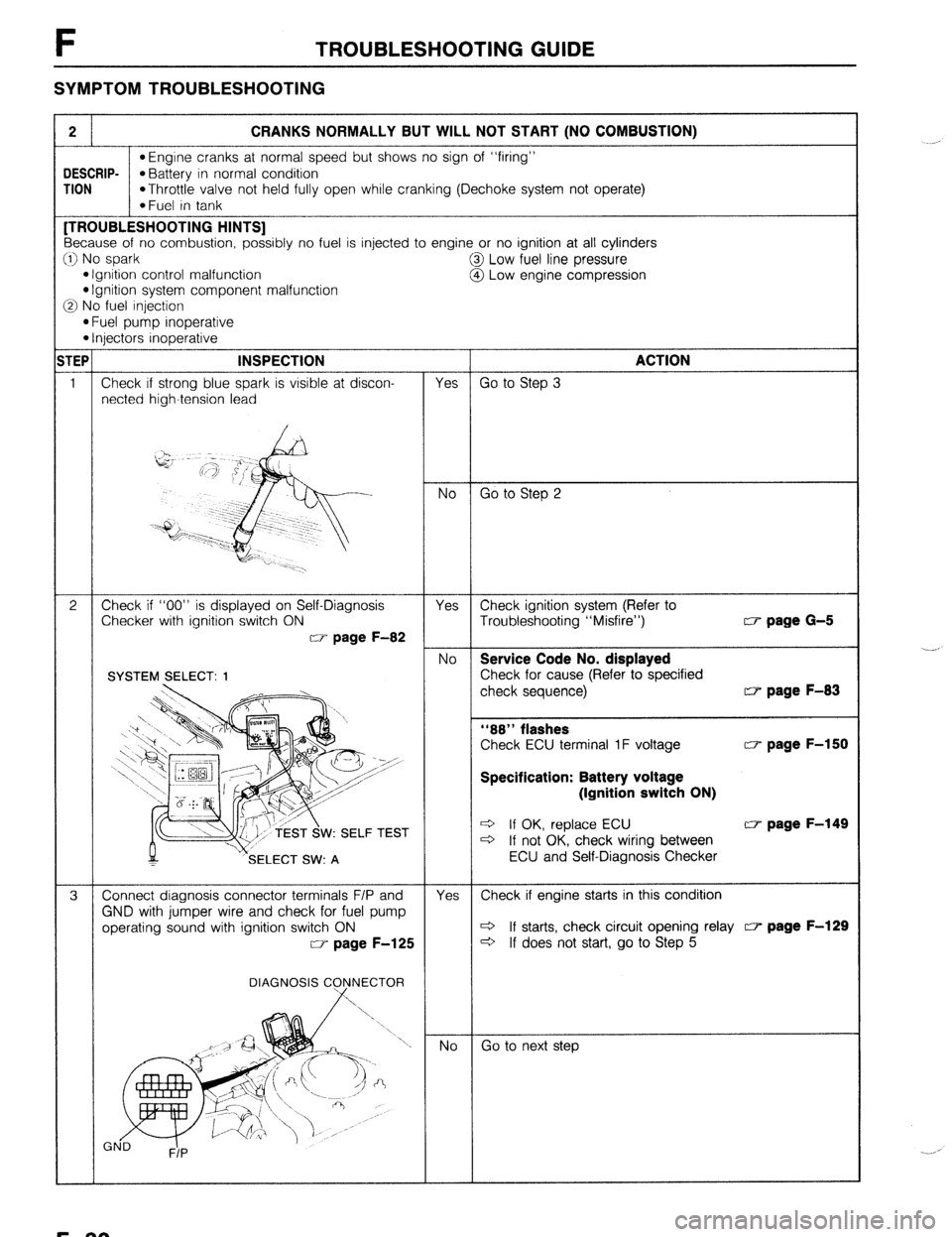
2 CRANKS NORMALLY BUT WILL NOT START (NO COMBUSTION)
l Engine cranks at normal speed but shows no sign of “firing”
DESCRIP-
*Battery in normal condition
TION
*Throttle valve not held fully open while cranking (Dechoke system not operate)
*Fuel in tank [TROUBLESHOOTING HINTS]
Because of no combustion, possibly no fuel is injected to engine or no ignition at all cylinders
:I) No spark
@I Low fuel line pressure
l Ignition control malfunction
@ Low engine compression l Ignition system component malfunction
3 No fuel injection
l Fuel pump inoperative l Injectors inoperative
TEP INSPECTION
ACTION
1 Check if strong blue spark is visible at discon-
Yes Go to Step 3
netted high-tension lead
No Go to Step 2
2 Check if “00” is displayed on Self-Diagnosis
Yes Check ignition system (Refer to
Checker with ignition switch ON
Troubleshooting “Misfire”) w page G-5
w page F-82
No Service Code No. displayed
Check for cause (Refer to specified
check sequence) w page F-83
“88” flashes
Check ECU terminal 1F voltage w page F-150
Specification: Battery voltage
(Ignition switch ON)
W: SELF TEST e If OK, replace ECU w page F-149 c3 If not OK, check wiring between
SELECT SW: A ECU and Self-Diagnosis Checker
3 Connect diagnosis connector terminals F/P and
Yes Check if engine starts in this condition
GND with jumper wire and check for fuel pump
operating sound with ignition switch ON c3 If starts, check circuit opening relay c7 page F-129
w page F-125
c3 If does not start, go to Step 5
DIAGNOSIS C
Go to next step ._-,
._. ,
F-30
Page 297 of 1164

TROUBLESHOOTING GUIDE F
w page F-125
tor (W/R) wire with ignition switch ON
MTX...lN, 2A, 2U, 2V
ATX... IT, 3A, 3U, 3V w page F-150
w page F-172
Fuel Line pressure:
265-314 kPa (2.7-3.2 kg/cm2, 36-46 psi)
fuel return hose w page F-129
fuel return hose is clogged or w page F-120
CT page F-130
(6.5 kg/cm2, 121 psi)-300 rpm
(9.0 kg/cm2, 128 psi)300 rpm
l Defective cylinder head gasket l Distorted cylinder head
WEAR AND C
AMAGE AND
ETERIORATION CT- page F-149
F-31
Page 298 of 1164

F TROUBLESHOOTING GUIDE
3 CRANKS NORMALLY BUT WILL NOT START (PARTIAL COMBUSTION) - WHEN ENGINE COLD
DESCRIP- *Engine cranks at normal speed but shows only partial combustion and will not continue to run
TION
l Battery in normal condition
*Fuel in tank
[TROUBLESHOOTING HINTS]
0 Air/Fuel mixture too rich
*Air cleaner element clogged
l Airflow meter stuck @ Low engine compression
@ Air/Fuel mixture too lean
l Fuel injection control malfunction
(Correction for coolant temperature)
*Low fuel line pressure
*Air leakage of intake air system
Checker with ignition switch ON
CT page F-83
w page F-150
Specification: Battery voltage
(Ignition switch ON)
W: SELF TEST w page F-149
Fuel line pressure:
285-314 kPa (2.7-3.2 kg/cm’, 38-48 psi) If fuel line pressure quickly in-
creases, check pressure regulator CF- page F-129
d If fuel line pressure gradually in-
creases check for clogging be-
I pump and pressure
Check if fuel return hose is clogged or
F-32
Page 299 of 1164

TROUBLESHOOTING GUIDE
TEP INSPECTION ACTION
4 Check if ECU terminal voltages are OK Yes Go to next step
MTX...Especially IC, 20 and 2Q
ATX... Especially lC, 2E and 3D v page F-150
No Check for cause ~3‘ page F-151
5
Check for air leakage of intake air system com- Yes Repair or replace
ponents
No Go to next step
6 Check if engine starts when water thermosensor Yes Check water thermosensor c7 page F-158 is disconnected
Check for correct engine compression 82-10 ’ No
Check engine condition CIP page Bl-10
Engine compression: 82-10
l BP SOHC l Worn piston, piston rings or cylinder 834 kPa (8.5 kg/cm*, 121 psi)300 rpm
wall
l BP DOHC l Defective cylinder head gasket 883 kPa (9.0 kg/cm*, 128 psi)-300 rpm l Distorted cylinder head
l B8 l Improper valve seating 932 kPa (9.5 kg/cm*, 135 psi)300 rpm *Valve sticking in guide
9 Check if spark plugs are OK Yes Go to next step CT- page G-18
1.0-l .l mm
(0.039-0.043 in) DAMAGE AND
DETERIORATION No Clean, or replace c7 page G-18
10 Try known good ECU and check if condition
improves CT- page F-149
23UOFX-01 I
F-33
Page 301 of 1164
TROUBLESHOOTING GUIDE F
TEPt INSPECTION ACTION
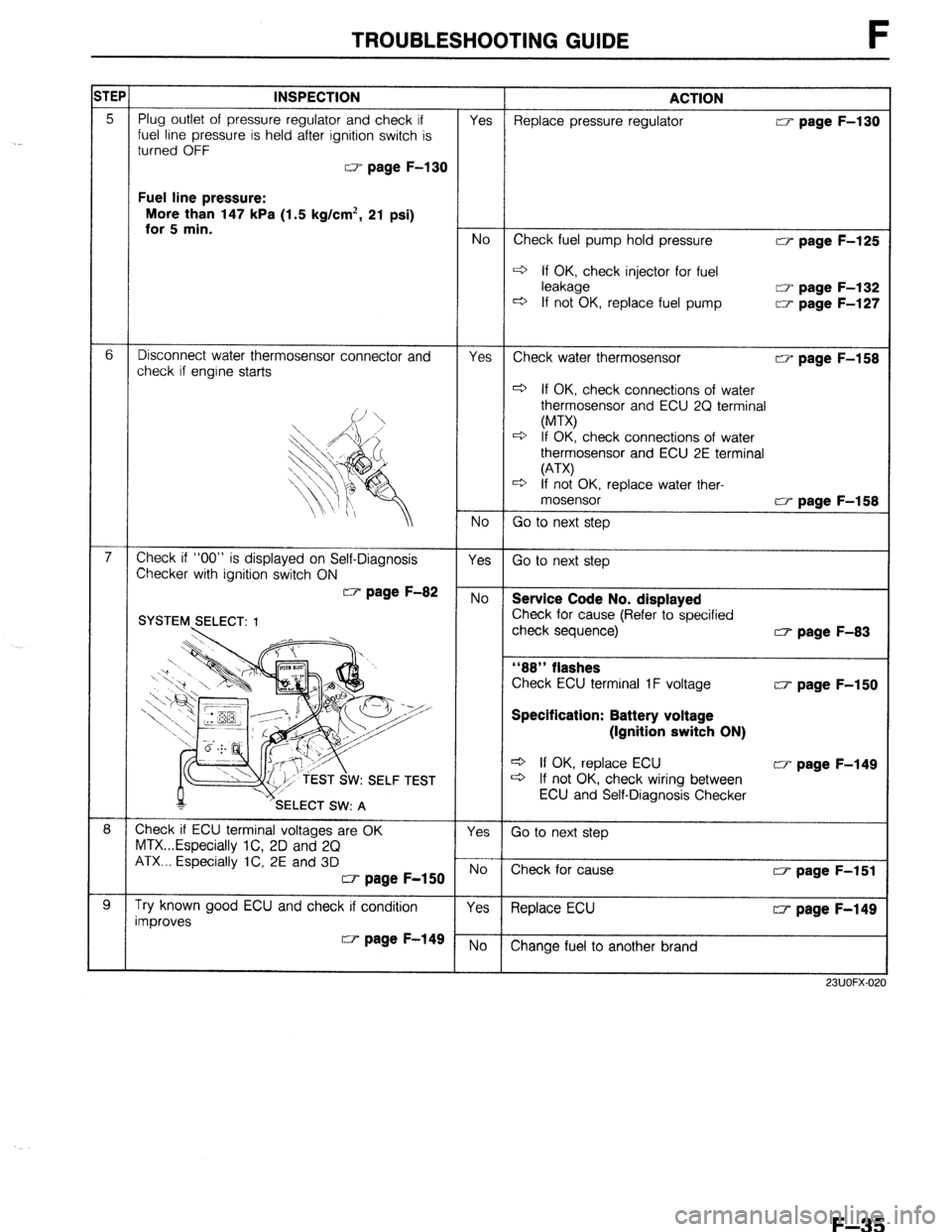
Fuel line pressure:
More than 147 kPa (1.5 kg/cm*, 21 psi)
w page F-125
4 If OK, check injector for fuel
w page F-132
w page F-127
w page F-158
+ If OK check connections of water
osensor and ECU 2Q terminal
check connections of water
osensor and ECU 2E terminal
K, replace water ther-
w page F-83
w page F-150
Specification: Battery voltage
(Ignition switch ON)
Q If OK, replace ECU CT page F-149
+ If not OK, check wiring between
ECU and Self-Diagnosis Checker
23UOFX-0:
F-35
Page 302 of 1164
F TROUBLESHOOTING GUIDE
5
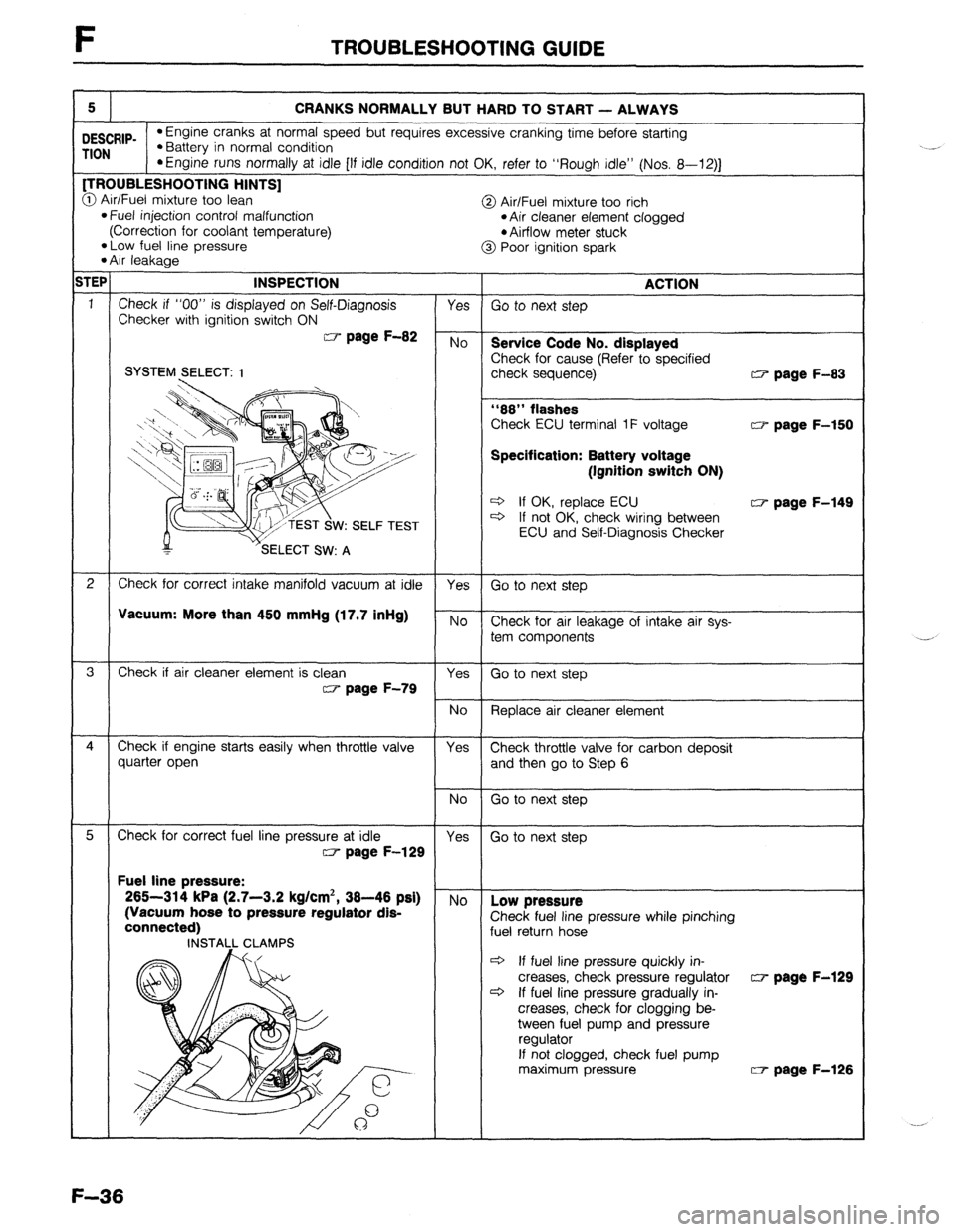
CRANKS NORMALLY BUT HARD TO START - ALWAYS
DESCRIP- l Engine cranks at normal speed but requires excessive cranking time before starting
TION l Battery in normal condition
*Engine runs normally at idle [If idle condition not OK, refer to “Rough idle” (Nos. 8-12)J [TROUBLESHOOTING HINTS]
@ Air/Fuel mixture too lean
@ Air/Fuel mixture too rich l Fuel injection control malfunction
(Correction for coolant temperature) *Air cleaner element clogged
l Airflow meter stuck
*Low fuel line pressure
l Air leakage @ Poor ignition spark
;TEP INSPECTION ACTION
1
Check if “00” is displayed on Self-Diagnosis Yes Go to next step
Checker with ignition switch ON W page F-82 No
Service Code No. displayed
Check for cause (Refer to specified SYSTEM SELECT: 1 check sequence) w page F-83
“88” flashes
Check ECU terminal 1F voltage w page F-150
Specification: Battery voltage
(Ignitlon switch ON)
* If OK, replace ECU w page F-149
W: SELF TEST c3 If not OK, check wiring between
ECU and Self-Diagnosis Checker
2 Check for correct intake manifold vacuum at idle
Yes Go to next step
VsCUUm: More than 450 mmHg (17.7 inHg) No Check for air leakage of intake air sys-
tem components
3 Check if air cleaner element is clean
Yes Go to next step w page F-79
No
Replace air cleaner element
4 Check if engine starts easily when throttle valve Yes Check throttle valve for carbon deposit
quarter open and then go to Step 6 Fuel line pressure:
265-314 kPa (2.7-3.2 kg/cm*, 38-46 psi)
(Vacuum hose to pressure regulator dis-
pressure while pinching
c3 If fuel line pressure quickly in-
creases, check pressure regulator w page F-129
c3 If fuel line pressure gradually in-
creases, check for clogging be-
tween fuel pump and pressure
If not clogged, check fuel pump
maximum pressure W- page F-126
F-36
Page 304 of 1164
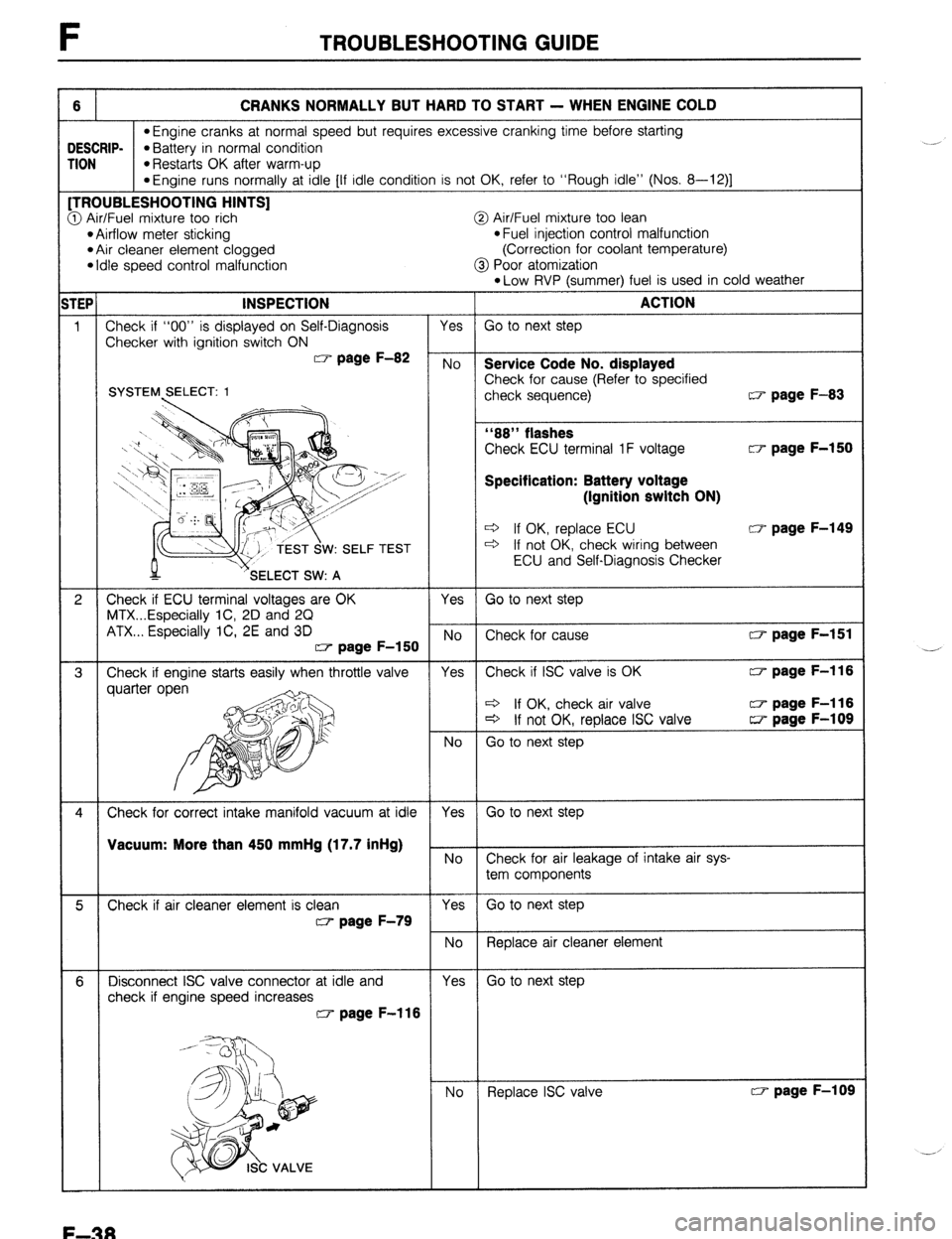
F TROUBLESHOOTING GUIDE
6 CRANKS NORMALLY BUT HARD TO START - WHEN ENGINE COLD
l Engine cranks at normal speed but requires excessive cranking time before starting )ESCRIP-
l Battery in normal condition UON
*Restarts OK after warm-up
*Engine runs normally at idle [If idle condition is not OK, refer to “Rough idle” (NOS. 8-124 [TROUBLESHOOTING HINTS]
3 Air/Fuel mixture too rich
@ Air/Fuel mixture too lean l Airflow meter sticking l Fuel injection control malfunction
*Air cleaner element clogged
(Correction for coolant temperature)
l Idle speed control malfunction
@ Poor atomization
*Low RVP (summer) fuel is used in cold weather
SYSTEM SELECT: 1
Check ECU terminal 1 F voltage CT- page F-150
Specification: Battery voltage
(Ignition switch ON)
c3 If OK, replace ECU CT page F-149 c3 If not OK, check wiring between
ECU and Self-Diagnosis Checker Vacuum: More than 450 mmHg (17.7 inHg)
.
No
Check for air leakage of intake air sys-
tem components
5 Check if air cleaner element is clean Yes
Go to next step
~7 page F-79
No
Replace air cleaner element
6 Disconnect ISC valve connector at idle and
Yes Go to next step
check if engine speed increases CT page F-l 16
No
Replace ISC valve CT page F-109
--’
F-38
Page 305 of 1164

TROUBLESHOOTING GUIDE F
1TEP INSPECTION
ACTION
7 Connect diagnosis connector terminals F/P and Yes
Go to next step
GND with jumper wire and check for correct fuel
line pressure with ignition switch ON w page F-122
No Low pressure
Check fuel line pressure while pinching Fuel line pressure:
265-314 kPa (2.7-3.2 kg/cm*, 38-46 psi) fuel return hose
c3 If fuel line pressure quickly in-
creases, check pressure regulator w page F-129
+ If fuel line pressure gradually in-
creases, check fuel line for clog-
ging between fuel pump and
pressure regulator
If not clogged, check fuel pump
maximum pressure High pressure w page F-126
Check if fuel return hose is clogged or
restricted
INSTALL CLAMPS c3 If OK, replace pressure regulator w page F-130 c3 If not OK, repair or replace hose
8
Try known good ECU and check if condition
Yes Replace ECU w page F-149
improves w page F-149 No
Change fuel to another brand
23UOFX-02
F-39