battery location MAZDA PROTEGE 1992 Workshop Manual
[x] Cancel search | Manufacturer: MAZDA, Model Year: 1992, Model line: PROTEGE, Model: MAZDA PROTEGE 1992Pages: 1164, PDF Size: 81.9 MB
Page 46 of 1164
Bl ON-VEHICLE MAINTENANCE
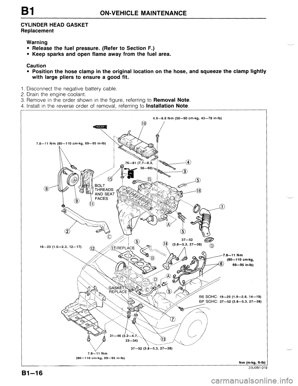
CYLINDER HEAD GASKET
Replacement
Warning
l Release the fuel pressure. (Refer to Section F.)
l Keep sparks and open flame away from the fuel area.
Caution
l Position the hose clamp in the original location on the hose, and squeeze the clamp lightly
with large pliers to ensure a good fit.
1. Disconnect the negative battery cable.
2. Drain the engine coolant.
3. Remove in the order shown in the figure, referring to Removal Note.
4. Install in the reverse order of removal, referring to Installation Note.
7.8-11 N.m
16-23 (1 4.9-8.8 N.m (50-90 cm-kg, 43-78 in-lb)
(80-l 10 cm-kg, 69-95 in-lb)
L
.8-11 N.m
(80-110 cm-kg,
69-95 in-lb)
-25 (1.9-2.6, 14-19)
BP SOHC: 37-52 (3.8-5.3, 27-38)
37-52 (3.8-5.3, 27-38)
7.8-11 N.m
(80-l 10 cm-kg, 89-95 in-lb)
N-m (m-kg, ft-lb)
23UOBl-01
81-16
Page 148 of 1164
82 ON-VEHICLE MAINTENANCE
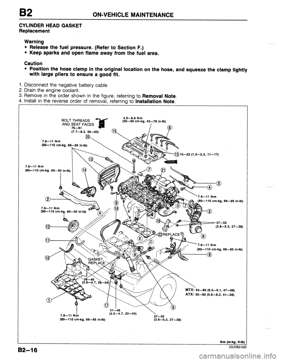
CYLINDER HEAD GASKET
Replacement
Warning
l Release the fuel pressure. (Refer to Section F.)
l Keep sparks and open flame away from the fuel area.
Caution
l Position the hose clamp in the original location on the hose, and squeeze the clamp lightly
with large pliers to ensure a good fit.
1. Disconnect the negative battery cable.
2. Drain the engine coolant.
3. Remove in the order shown in the figure, referring to
Removal Note.
4. install in the reverse order of removal, referrina to Installation Note.
BOLT THREADS ?&d 4.9-8.8 N.m
fsn-an om.h 41-‘71( ir
AND SEAT FACES ,-- -- -... ..=, _” . _ ..I-lb)
78-81 - /
(7.7-8.3, 58-60)
7.8-11 N.m
(80-l 10 cm-ka, 69-95
, . . . . . . (80-l 10 cm-kg, 69-9: in-lb) (j-$15-23 (1.5-2.3, 11-17)
82-l 6
7.8-11 N.m
(80-110 cm-k?, 69-95 In-lb) 180-110 cm-ka. 69-95 in-lb
-37-52
(3.8-5.3, 27-38)
’
nl MTX:?64-69 (6.6-9.1,
PTX: 55-60 (6.6-8.2, 69-95 in. .Ib)
47-86)
41-69)
7.8-11 N./n (3.2-4.7, 23-34)
37-52
(80-110 cm-kg, 69-95 in-lb) (3.8-5.3, 27-38)
N-m (m-kg, N-lb)
^^. .^_^ __
Page 256 of 1164

E RADIATOR
RADIATOR
REMOVAL / INSTALLATION
Caution
l Position the hose clamp in the original location on the hose, and squeeze the clamp lightly
with large pliers to ensure a good fit.
1. Disconnect the negative battery cable.
2. Drain the engine coolant.
3. Remove in the order shown in the figure.
4. Install in the reverse order of removal.
7.8-11 N.m (80-110 cm-kg, 69-95 in-lb)
-...__--- --- i
771 InFu.nnc; cvyILII ..,.,..
6. Oil cooler hose (ATX)
7. Radiator bracket
8. Radiator
Inspection . . . . . . . . . . . . . . . . . . . . . . . . . . . . . . . . . . . . . page E-9
9. Cooling fan and radiator cowling assembly 1. Resonance chamber
2. Cooling fan connector
3. Radiator thermoswitch connector (BP ATX)
4. Coolant reservoir hose
5. Radiator hose i
Y’
E-8
Page 257 of 1164
RADIATOR, THERMOSTAT t
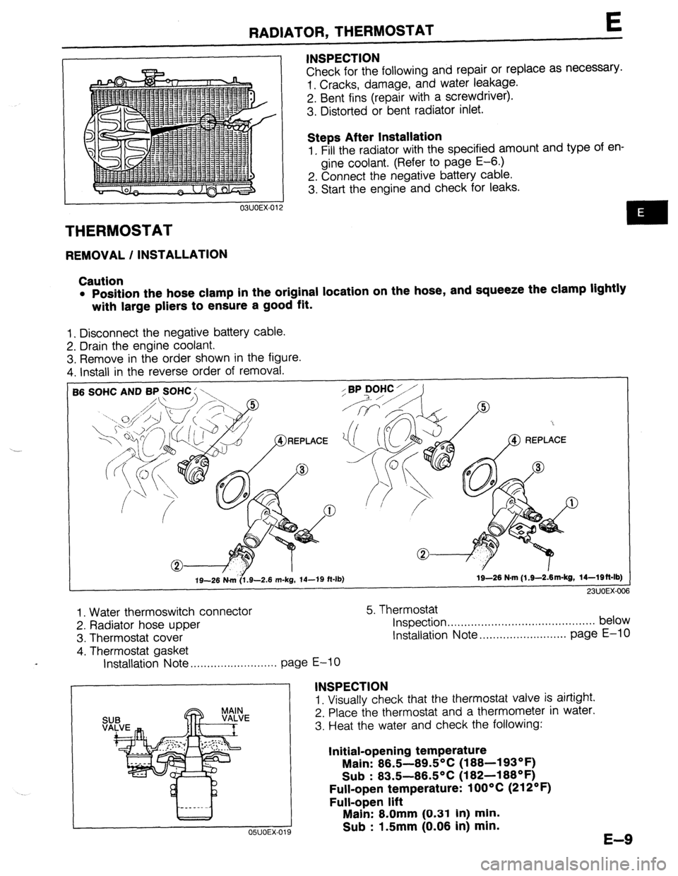
THERMOSTAT
REMOVAL / INSTALLATION INSPECTION
Check for the following and repair or replace as necessary.
1. Cracks, damage, and water leakage.
2. Bent fins (repair with a screwdriver).
3. Distorted or bent radiator inlet.
Steps After Installation
1. Fill the radiator with the specified amount and type of en-
gine coolant. (Refer to page E-6.)
2. Connect the negative battery cable.
3. Start the engine and check for leaks.
Caution
l Position the hose clamp in the original location on the hose, and squeeze the clamp lightly
with large pliers to ensure a good fit.
1. Disconnect the negative battery cable.
2. Drain the engine coolant.
3. Remove in the order shown in the figure.
4. Install in the reverse order of removal.
SOHC AND BP SOHC : \,
19-26 N&6.9-2.6 m-kg, 14-19 ft-lb) 19-26 N-m (l.S--2&m-kg, 14-Wft-lb)
23UOEX-006
1. Water thermoswitch connector
2. Radiator hose upper
3. Thermostat cover
4. Thermostat gasket 5. Thermostat
Inspection . . . . .., .., ,.. ,.. . . . ,.. . . . . . . . . . . . . . . . . . . . . . . below
Installation Note ..,....................... page E-10
Installation Note . . . . . . . . . . . . . . . . . . . . . . . . . .
page E-10
INSPECTION
1. Visually check that the thermostat valve is airtight.
2. Place the thermostat and a thermometer in water.
3. Heat the water and check the following:
Initial-opening temperature
Main: 86.5-89.5°C (188-193OF)
Sub : 83.5-86.5OC (182-188OF)
Full-open temperature: 1 OOOC (212OF)
Full-open lift
OSUOEX-019
Main: 8.0mm (0.31 In) min.
Sub : 1.5mm (0.06 in) min.
E-9
Page 263 of 1164

FAN MOTOR E
I-
i.- 5. Connect the battery, an ammeter, and switch to the fan mo-
tor connectors for high-speed inspection.
6. Verify that the fan motor operates smoothly at the standard
current or less with the switch ON.
Current (A): 13.3 + 10% MAX
7. If the fan motor is faulty, replace it.
---“-. --
REPLACEMENT
Caution
l Position the hose clamp in the original location on the hose, and squeeze the clamp lightly
with large pliers to ensure a good fit.
1. Disconnect the negative battery cable.
2. Drain the engine coolant.
3. Remove in the order shown in the figure.
4. Install in the reverse order of removal.
7.8-11 N.m
7.8-11 N.m
(80-110 cm-kg,
1. Resonance chamber
4. Radiator cowling
2. Cooling fan connector
5.
Cooling fan
3. Radiator hose upper
6. Fan motor
E-l 5
Page 351 of 1164

SELF-DIAGNOSIS FUNCTION F
:ODE LOCATION OF
NO.
MALFUNCTION
26 Solenoid valve ON
(purge control)
OFF OUTPUT SIGNAL PATTERN nnnnnll 1 SELF4IAGNOSIS
Open or
short circuit FAIL-SAFE
-
ON
34
ISC valve
OFF u 1 llllJlll r -
41 Solenoid valve ON
(WCS)
[DOHC]
OFF -
Pulse ON No input signal Shifting performed in
55*
i nnnnn
from pulse accordance with signals
generator
OFF generator from vehicle speed
sensor
Open or Solenoid valve(s)
60* 1-2 shift ON
short circuit
solenoid valve
uuuuul performs the shifting with
as little interference as
OFF
possible with driving
performance
2-3 shift ON Lockup not provided
61*
solenoid valve
OFF
UUUI n
3-4 shift ON
62’
solenoid valve
OFF u u u u inn
1.6 sec. 4 sec.
63* Lockup solenoid
valve
u u&m I- Shifting performed
normally
Lockup not provided
0.4 sec.
0.4 sec.
*If the marked code numbers appeor, refer to Section K
Note
l The HOLD indicator does not flash the service code numbers.
l If there is more than one failure present, the code numbers will be indicated in numerical or-
der, lowest number first.
* After repairing a problem, turn the ignition switch OFF and disconnect the negative battery
cable at least 20 seconds to erase the service code numbers from the engine control unit (ECU)
memory.
23UOFX-051
F-85
Page 962 of 1164
U TROUBLESHOOTING GUIDE
Symptom: Blower motor does not operate.
Normal operation of blower motor
Blower motor speed is controlled by the blower switch and a resistor assembly in the blower unit.
When the blower switch is in the OFF position, the motor ground circuit is open and the blower motor does
not operate. When the switch is in the first (Low) position, current flow from the blower motor is restricted
by the three resistors in the resistor assembly, and the blower motor turns at low speed.
Changing the blower switch to the second (Mid), third (High), or fourth (Super-high) positions causes the
circuit resistance to decrease, and the blower motor speed to become correspondingly faster.
03uoux-005
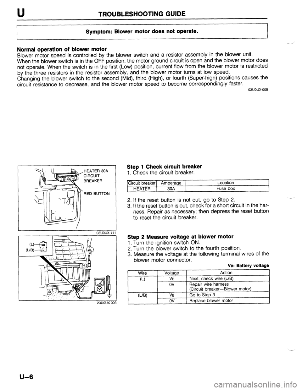
. HEATER 30A
CIRCUIT
BREAKER
RED BUTTON
23UOUX-01
Step 1 Check circuit breaker
1. Check the circuit breaker.
ircuit breaker] Amperage ( Location
HEATER 1 30A Fuse box
2. If the reset button is not out, go to Step 2.
3. If the reset button is out, check for a short circuit in the har-
ness. Repair as necessary; then depress the reset button
to reset the circuit breaker.
Step 2 Measure voltage at blower motor
1. Turn the ignition switch ON.
2. Turn the blower switch to the fourth position.
3. Measure the voltage at the following terminal wires of the
blower motor connector.
VB: Battery voltage
Wire
Voltage Action
a-) VB Next, check wire (L/B)
ov ReDair wire harness
(Ciicuit breaker-Blower motor)
U-W VB Go to Step 3
ov Replace blower motor
U-6
Page 968 of 1164
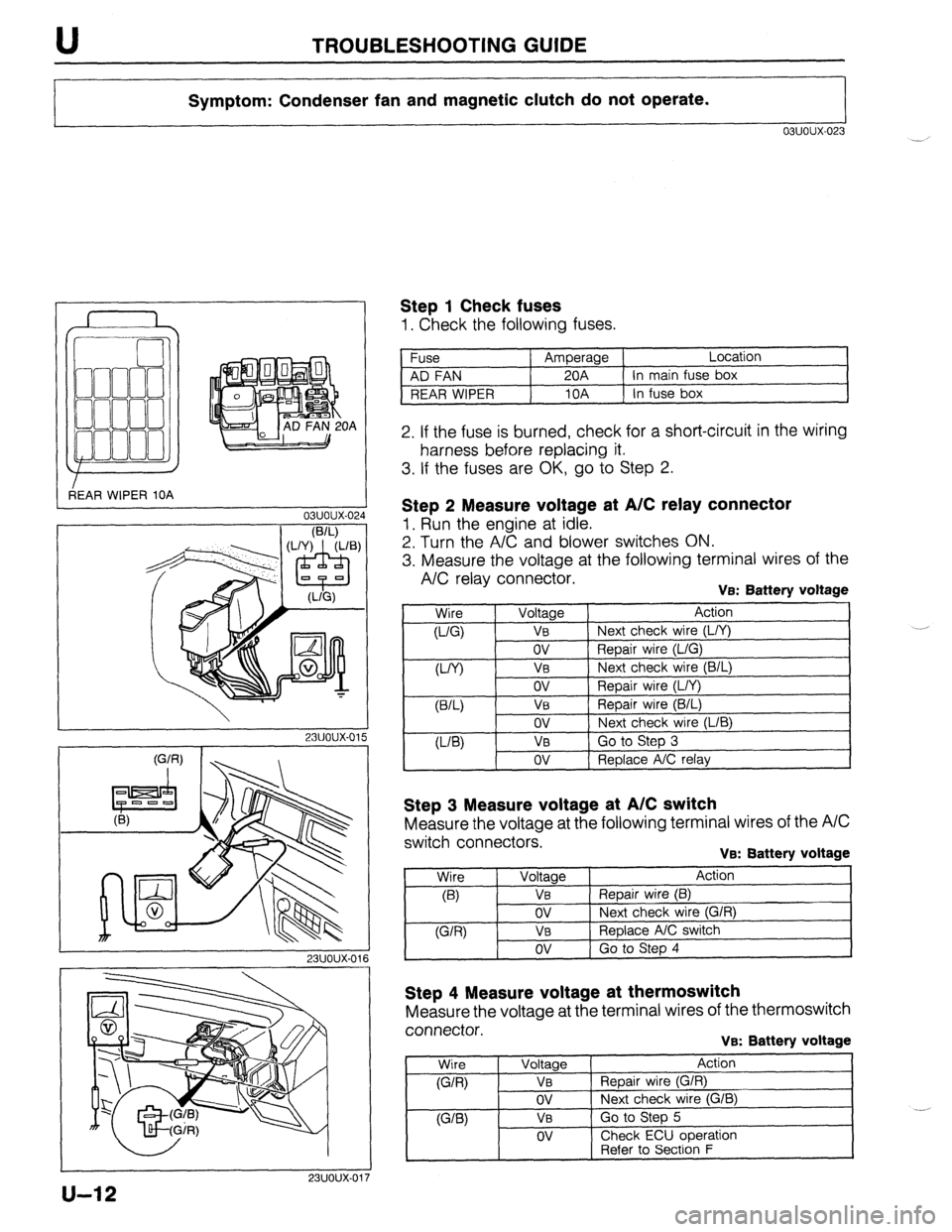
TROUBLESHOOTING GUIDE
Symptom: Condenser fan and magnetic clutch do not operate.
03uoux-023
r
3EAR WIPER 10A OA
L
03uoux-02.
I
1 Step 1 Check fuses
1. Check the following fuses.
Fuse Amperage Location
AD FAN 20A In main fuse box
REAR WIPER 10A In fuse box
2. If the fuse is burned, check for a short-circuit in the wiring
harness before replacing it.
3. If the fuses are OK, go to Step 2.
I
23uoux-011
Step 2 Measure voltage at A/C relay connector
1. Run the engine at idle.
2. Turn the A/C and blower switches ON.
3. Measure the voltage at the following terminal wires of the
A/C relay connector. VEX Battery voltage
,
Wire
0-Q
W) Voltage Action
VB Next check wire (L/Y)
ov Repair wire (L/G)
V0 Next check wire (B/L)
ov
VB
ov
VB
ov Repair wire (L/Y)
Repair wire (B/L)
Next check wire (LIB)
Go to Step 3
Replace A/C relay
Step 3 Measure voltage at A/C switch
Measure the voltage at the following terminal wires of the A/C
switch connectors.
VB: Battery voltage
Step 4 Measure voltage at thermoswitch
Measure the voltage at the terminal wires of the thermoswitch
connector.
VB: Battery voltage
Wire
(G/R)
WB)
Voltage
VB
ov
VB
OV
Action
Repair wire (G/R)
Next check wire (G/B)
Go to Step 5
Check ECU ooeration
1 -. [ Refer to Secti6n F
u-12
Page 1058 of 1164
Z-Gl-2 Contents of and Using Electrical Wiring Diagrams
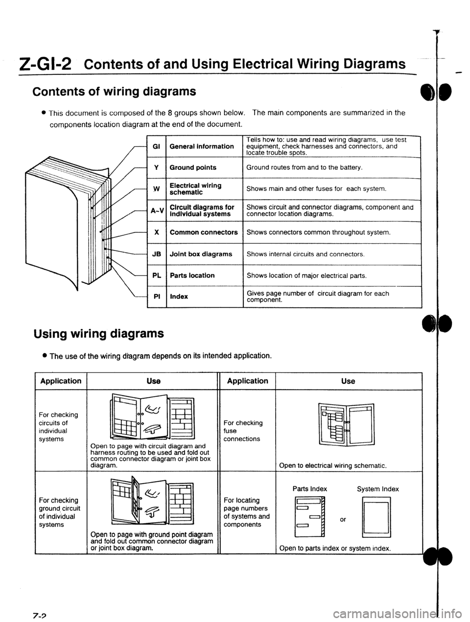
Contents of wiring diagrams
l This document is composed of the 8 groups shown below. The main components are summarized in the
components location diagram at the end of the document.
Tells how to: use and read wiring dragrams, use test
GI General information equipment, check harnesses and connectors, and
locate trouble spots.
Y Ground points Ground routes from and to the battery.
I
w
I Electrical wiring
schematic
I Shows main and other fuses for each system.
lndlvidual systems
I Shows circuit and connector diagrams, component and
connector location diagrams.
1
X
I Common connectors
I Shows connectors common throughout system.
I
JB Joint box diagrams Shows internal circuits and connectors.
PL Parts location Shows location of major electrical parts.
PI Index
I
I
Gives page number of circuit diagram for each
component.
Using wiring diagrams
l The use of the wiring diagram depends on its intended application. Application
For checking
circuits of
individual
systems
For checking
ground circuit
of individual
systems 7-3 Use
II Application
Open to page with circuit diagram and
harness routing to be used and fold out
common connector diagram or joint box
diagram. For checking
fuse
connections Use
Open to electrical wiring schematic.
Open to page with ground point diagram
and fold out common connector diagram
or joint box diagram. For locating
page numbers
of systems and
components Parts Index
H
Open to parts index or system index.
Page 1072 of 1164
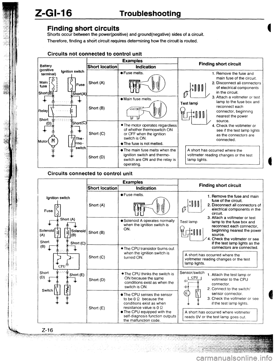
II-GM6 Troubleshooting
Finding short circuits
Shorts occur between the power(positive) and ground(negative) sides of a circuit.
Therefore, finding a shdit circuit requires determining how the circuit is routed.
Circuits not connected to control unit
Examples
Indication
0 Fuse melts. Finding short circuit
0
Test lamp 1. Remove the fuse and
main fuse of the circurt.
2. Disconnect all connectors
of electrical components
in the circuit.
3. Attach a voltmeter or test
lamp to the fuse box and
reconnect each
connector, beginning
nearest the power
source.
4. Check the voltmeter or
see if the test lamp lights
as the connectors are
connected. Finding short circuit
,,{:““o
1. Remove the fuse and main
fuse of the circuit.
2. Disconnect all connectors of
/ electrical components in the
circuit.
Test lamp 3. Attach a voltmeter or test
lamp to the fuse box and
reconnect each connector,
beginning nearest the power
4. Check the voltmeter or see
if the test lamp lights as the
connectors are connected.
Sensor/switch
1. Attach the test lamp or
voltmeter to the CPU
connector.
2. Connect to the swrtch/
sensor connector.
3. Check the voltmeter or see
if the test lamp lights.
A short has occurred where voltmeter
reads OV or the test lamp goes out,
- Short location
Battery Short (A)
l Main fuse melts.
L* Short(B)
0 The motor operates regardless
of whether thermoswitch ON
or OFF when the ignition
switch is ON. Short (C)
lotor
M
P The-
tmo-
switc *The fuse is not melted.
@The main fuse melts when the
ignition switch and thermo-
switch are ON and the relay is
operating. Short (D)
Circuits connected to control unit
-T Examples
Indication
l Fuse melts.
- Short locatior
I
ignition switch
I
Fuse R-l Short (A)
J+L--l
Short (A) l Solenoid A operates normally
when the ignition switch is
ON.
9enold m rfr solenok
;<
A) u a(B) ’ Short (6)
l The CPU transistor burns out
when the ignition switch is
turned ON. Short (C)
l The CPU thinks the switch is
ON because the same
conditions exist as when the
switch is ON.
*The CPU senses the sensor
to be 0 R because the
conditions exist as when
resistance value is 0 R
*The CPU equipped with the
self-diagnosis function output
the malfunctron code. Short (0)
Swltcl1 ml
Short (E) Z-16