weight MAZDA PROTEGE 1992 Workshop Manual
[x] Cancel search | Manufacturer: MAZDA, Model Year: 1992, Model line: PROTEGE, Model: MAZDA PROTEGE 1992Pages: 1164, PDF Size: 81.9 MB
Page 81 of 1164

DISASSEMBLY Bl
23UOBl-03
05UOBX-1’ 9
23UOBl-040
03UOBl-08 5
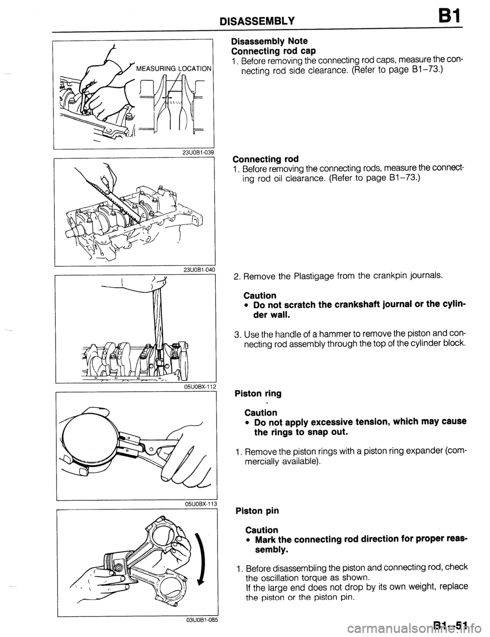
Disassembly Note
Connecting rod cap
1. Before removing the connecting rod caps, measure the con-
necting rod side clearance. (Refer to page Bl-73.)
Connecting rod
1. Before removing the connecting rods, measure the connect-
ing rod oil clearance. (Refer to page Bl-73.)
2. Remove the Plastigage from the crankpin journals.
Caution
l Do not scratch the crankshaft journal or the cylin-
der wall.
3. Use the handle of a hammer to remove the piston and con-
necting rod assembly through the top of the cylinder block.
Piston ring
Caution
l Do not apply excessive tension, which may cause
the rings to snap out.
1. Remove the piston rings with a piston ring expander (com-
mercially available).
Piston pin
Caution
l Mark the connecting rod direction for proper reas-
sembly.
1. Before disassembling the piston and connecting rod, check
the oscillation torque as shown.
If the large end does not drop by its own weight, replace
the piston or the piston pin.
81-51
Page 201 of 1164

ASSEMBLY
2311082-04
05UOBX-17
OSUOBX-17
SPACER TANG
OIL RING
SPACER ENDS
-I
a
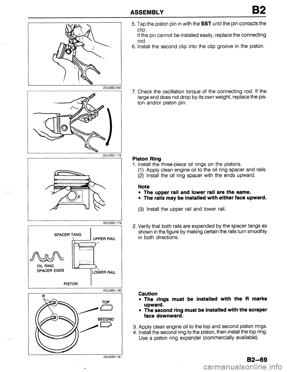
5. Tap the piston pin in with the SST until the pin contacts the
clip.
If the pin cannot be installed easily, replace the connecting
rod.
6. Install the second clip into the clip groove in the piston.
7. Check the oscillation torque of the connecting rod. If the
large end does not drop by its own weight, replace the pis-
ton and/or piston pin.
Piston Ring
1. Install the three-piece oil rings on the pistons.
(1) Apply clean engine oil to the oil ring spacer and rails.
(2) Install the oil ring spacer with the ends upward.
Note
l The upper rail and lower rail are the same.
l The rails may be installed with either face upward.
(3) Install the upper rail and lower rail.
2. Verify that both rails are expanded by the spacer tangs as
shown in the figure by making certain the rails turn smoothly
in both directions.
Caution
l The rings must be installed with the Fl marks
upward.
l The second ring must be installed with the scraper
face downward.
3. Apply clean engine oil to the top and second piston rings.
4. install the second ring to the piston; then install the top ring.
Use a piston ring expander (commercially available).
132-69
Page 706 of 1164

WHEELS AND TIRES
L 13UOQX-005
FRONT
13UOQX-006
G=a I) OUTSIDE
BALANC
WEIGHT
REMOVAL / INSTALLATION
1. The wheel-to-hub contact surfaces must be clean.
2. Tighten the lug nuts to the specified torque.
Tightening torque:
88-l 18 N-m (9-12 m-kg, 85-87 ft-lb)
Caution
l When reinstalling a wheel, retighten the lug nuts to
the specified torque after about 1,000 km (820 miles)
driving.
TIRE ROTATION
To prolong tire life and assure uniform tire wear, rotate the tires
from every 3,000 km (1,860 miles) to every 6,000 km (3,720
miles).
Caution
l Do not include “TEMPORARY USE ONLY” spare tire
in rotation.
l Use the best tires on the front axle.
l After rotating the tires, adjust each tire to the speci-
fied air pressure. (Refer to page Q-3.)
WHEEL BALANCE ADJUSTMENT
If a wheel becomes unbalanced or if a tire is replaced or
repaired, the wheel must be rebalanced to within specification.
Maximum unbalance (at rim edge)
13 inch wheel: 11 g (0.39 oz)
14 inch wheel: 10 g (0.35 or)
Caution
l Do not use more than two balance weights on the
inner or outer side of the wheel.
l If the total weight exceeds 1OOg (3.5 oz) perslde,
rebalance after moving the tire around on the rim.
l Attach the balance weights tightly on the wheel.
l Select suitable balance weights for steel or alumi-
num alloy wheels.
l Do not use an on-car balancer on automatic trans-
axle models; it may cause transaxle damage.
.__’
Q-6