towing MERCEDES-BENZ C-CLASS COUPE 2015 Owner's Guide
[x] Cancel search | Manufacturer: MERCEDES-BENZ, Model Year: 2015, Model line: C-CLASS COUPE, Model: MERCEDES-BENZ C-CLASS COUPE 2015Pages: 385, PDF Size: 13.12 MB
Page 318 of 385
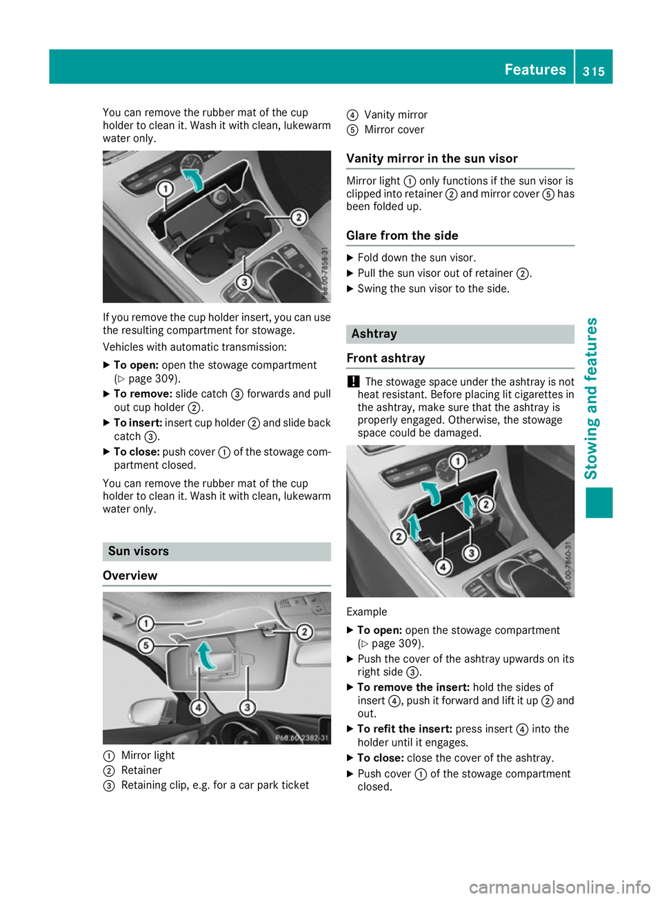
You can remove the rubber mat of the cup
holder to clean it. Wash it with clean ,lukewarm
water only. If you remove the cup holder insert, you can use
the resulting compartmen tfor stowage.
Vehicles with automatic transmission:
X To open: open the stowage compartment
(Y page 309).
X To remove: slide catch=forwards and pull
out cup holder ;.
X To insert: insertcup holder ;and slide back
catch =.
X To close: push cover :of the stowage com-
partmen tclosed.
You can remove the rubber mat of the cup
holder to clean it. Wash it with clean ,lukewarm
water only. Sun visors
Overview :
Mirro rlight
; Retainer
= Retaining clip, e.g. for acar park ticket ?
Vanit ymirror
A Mirro rcover
Vanity mirror in th esun visor Mirro
rlight :only function sifthe sun visor is
clipped int oretainer ;and mirror cover Ahas
been folded up.
Glar efromt heside X
Fold down the sun visor.
X Pull the sun visor out of retainer ;.
X Swin gthe sun visor to the side. Ashtray
Front ashtray !
The stowage space under the ashtray is not
heat resistant .Before placin glit cigarettes in
the ashtray, make sure that the ashtray is
properly engaged. Otherwise, the stowage
space could be damaged. Example
X To open: open the stowage compartment
(Y page 309).
X Push the cover of the ashtray upwards on its
right side =.
X To remove th einsert: hold the sides of
insert ?,push it forwar dand lift it up ;and
out.
X To refit th einsert: press insert ?intot he
holder until it engages.
X To close: close the cover of the ashtray.
X Push cover :of the stowage compartment
closed. Features
315Stowing and features Z
Page 319 of 385
i
You can remove the ashtray inser
tand use
the resulting compartmen tfor stowage.
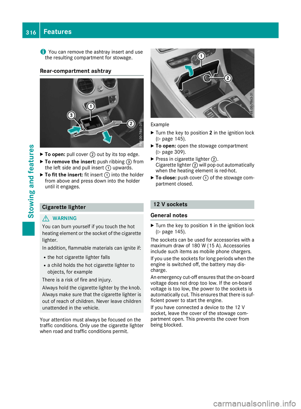
Rear-compartment ashtray X
To open: pull cover ;out by its top edge.
X To remove th einsert: push ribbing =from
the left side and pull insert :upwards.
X To fit th einsert: fit insert :intot he holder
from above and press down int othe holder
until it engages. Cigarett
elighter G
WARNING
You can burn yourself if you touc hthe hot
heatin gelemen torthe socket of the cigarette
lighter.
In addition ,flammable materials can ignit eif:
R the hot cigarett elighter falls
R ac hild holds the hot cigarett elighter to
objects, for example
There is arisk of fire and injury.
Always hold the cigarett elighter by the knob.
Always make sure that the cigarett elighter is
out of reach of children. Never leave children unattended in the vehicle.
Your attention must always be focused on the
traffic conditions. Only use the cigarett elighter
when road and traffic condition spermit. Example
X Turn the key to position 2in the ignition lock
(Y page 145).
X To open: open the stowage compartment
(Y page 309).
X Press in cigarett elighter ;.
Cigarette lighter ;will pop out automatically
when the heatin gelemen tisred-hot.
X To close: push cover :of the stowage com-
partmen tclosed. 12
Vsockets
Genera lnotes X
Turn the key to position 1in the ignition lock
(Y page 145).
The sockets can be used for accessories with a
maximum draw of 180 W(15 A). Accessories
include such item sasmobile phon echargers.
If you use the sockets for long periods when the engin eisswitched off, the battery may dis-
charge.
An emergenc ycut-of fensures that the on-board
voltage does not drop too low. If the on-board
voltage is too low, the power to the sockets is
automatically cut .This ensures that there is suf-
ficient power to star tthe engine.
If you have connected adevic etot he 12 V
socket, leave the cover of the stowage com-
partmen topen. This prevent sthe cover from
being blocked. 316
FeaturesStowing and features
Page 320 of 385

Socket in the front centre console
X
To open: open the stowage compartment
(Y page 309).
X Lift up the cover of the socket.
X To close: push the cover of the stowage com-
partment closed.
Socket in the rear-compartment centre
console X
Pull the cover out by the top of its handle
edge.
X Lift up the cover of the socket. 230
Vsocket
Important safety notes G
DANGER
When asuitable device is connected, the
230 Vpower socket will be carrying ahigh
voltage. You could receive an electric shock if the connector cable or the 230 Vpower
socket is pulled out of the trim or is damaged
or wet. There is arisk of fatal injury.
R Use only connector cables that are dry and
free of damage.
R When the ignition is off, make sure that the
230 Vpower socket is dry.
R Immediately have the 230 Vpower socket
checked or replaced at aqualified special-
ised workshop if it is damaged or has been
pulled out of the trim.
R Never plug the connector cable into a230 V
power socket that is damaged or has been pulled out of the trim. G
DANGER
If you reach into the power socket or plug
inappropriate devices into the power socket,
you could receive an electric shock. There is a risk of fatal injury.
Only attach appropriate objectstot he power
socket. !
Note that work and repairs on the 230 V
power socket should only be carried out by
qualified specialist personnel.
General notes The 230
Vpower socket provides an alternating
voltage of 230 Vsothat small electronic devices
can be connected. These devices, such as
games consoles, chargers and laptops, must not
consume more than amaximum of 150 watts
altogether.
Do not connect any multiple socket outlets to
the 230 Vpower socket.
Requirements for operating these devices:
R the electronic device that you connect has a
suitable connector and conforms to stand-
ards specific to the country you are in
R the electronic device connector is plugged
into the 230 Vpower socket
R the maximum wattage of the device to be
connected must not exceed 150 watts
R the on-board voltage is within apermissible
voltage range
R the 12 Vsocket in the front centre console is
working properly (Y page 317)
Using the 230 Vpower socket X
To switch on: switch the ignition on.
X Open flap =.
X Insert the electronic device connector into
230 Vpower socket :.
Indicator lamp ;lights up.
X To switch off: remove the connector from
230 Vpower socket :.
Make sure that you do not pull on the cable. Features
317Stowing and features Z
Page 321 of 385
Problems with the 230
Vpower socket Problem
Possible causes/consequences and
M
MSolutions The warning lamp on the
230 Vpower socket is
not lit. The on-board voltage is too low because the battery is too weak.
X Start the engine.
or X Charge the battery (Y page 343).
If the indicator lamp still does not light up: X Consult aqualified specialist workshop. The temperature of the DC/AC converter is temporarily too high.
X Remove the electronic device connector from the 230 Vsocket.
X Let the DC/AC converter cool down.
If the indicator lamp still does not light up after the converter cools
down:
X Consult aqualified specialist workshop. You have connected an electronic device that has
aconstant nominal
power of less than 150 watts, but has avery high switch-on current.
This device will not work. If you connect such adevice, the 230 V
power socket will not supply it with power.
X Connect asuitable electronic device. Mercedes-Benz emergency call sys-
tem
Information on these requirements can be found in the separate multimedia system operating
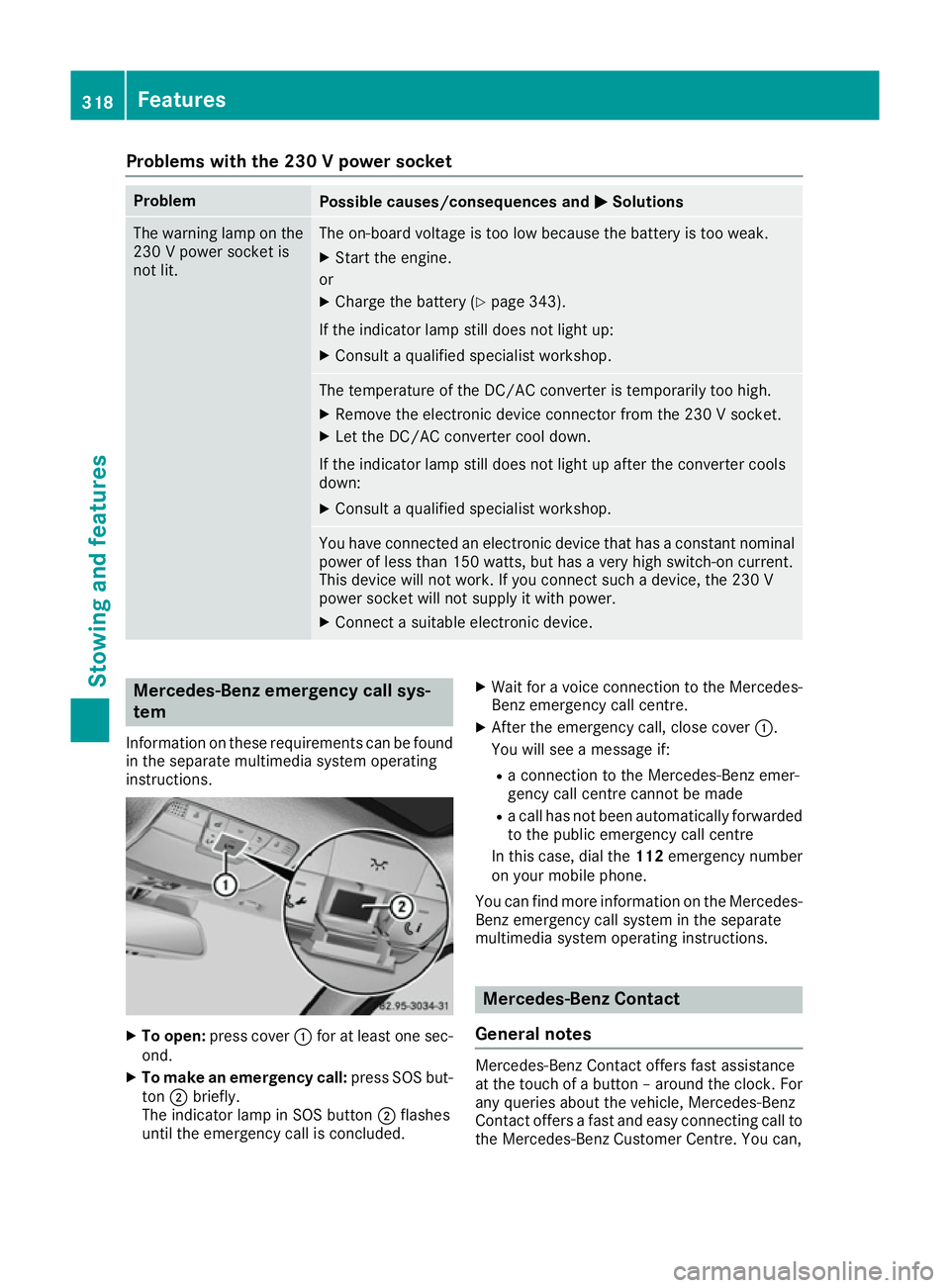
instructions. X
To open: press cover :for at least one sec-
ond.
X To make an emergency call: press SOS but-
ton ;briefly.
The indicator lamp in SOS button ;flashes
until the emergency call is concluded. X
Wait for avoice connection to the Mercedes-
Benz emergency call centre.
X After the emergency call, close cover :.
You will see amessage if:
R ac onnection to the Mercedes-Benz emer-
gency call centre cannot be made
R ac all has not been automatically forwarded
to the public emergency call centre
In this case, dial the 112emergency number
on your mobile phone.
You can find more information on the Mercedes- Benz emergency call system in the separate
multimedia system operating instructions. Mercedes-Benz Contact
General notes Mercedes-Benz Contact offers fast assistance
at the touch of
abutton –around the clock. For
any queries about the vehicle, Mercedes-Benz
Contact offers afast and easy connecting call to
the Mercedes-Benz Customer Centre. You can, 318
FeaturesStowing and features
Page 322 of 385
for example, request an appointment or call for
help in the event of abreakdown.
The Audi o20/COMAND Online display indi-
cates that acall is active. During the call ,you
can change to the navigation menu by pressing
the NAVI button on the multimedi asystem ,for
example.
Voice outpu tisnot available in this case.
You can find more information on Mercedes-
Benz Contact in the separate multimedi asys-
tem operating instructions.
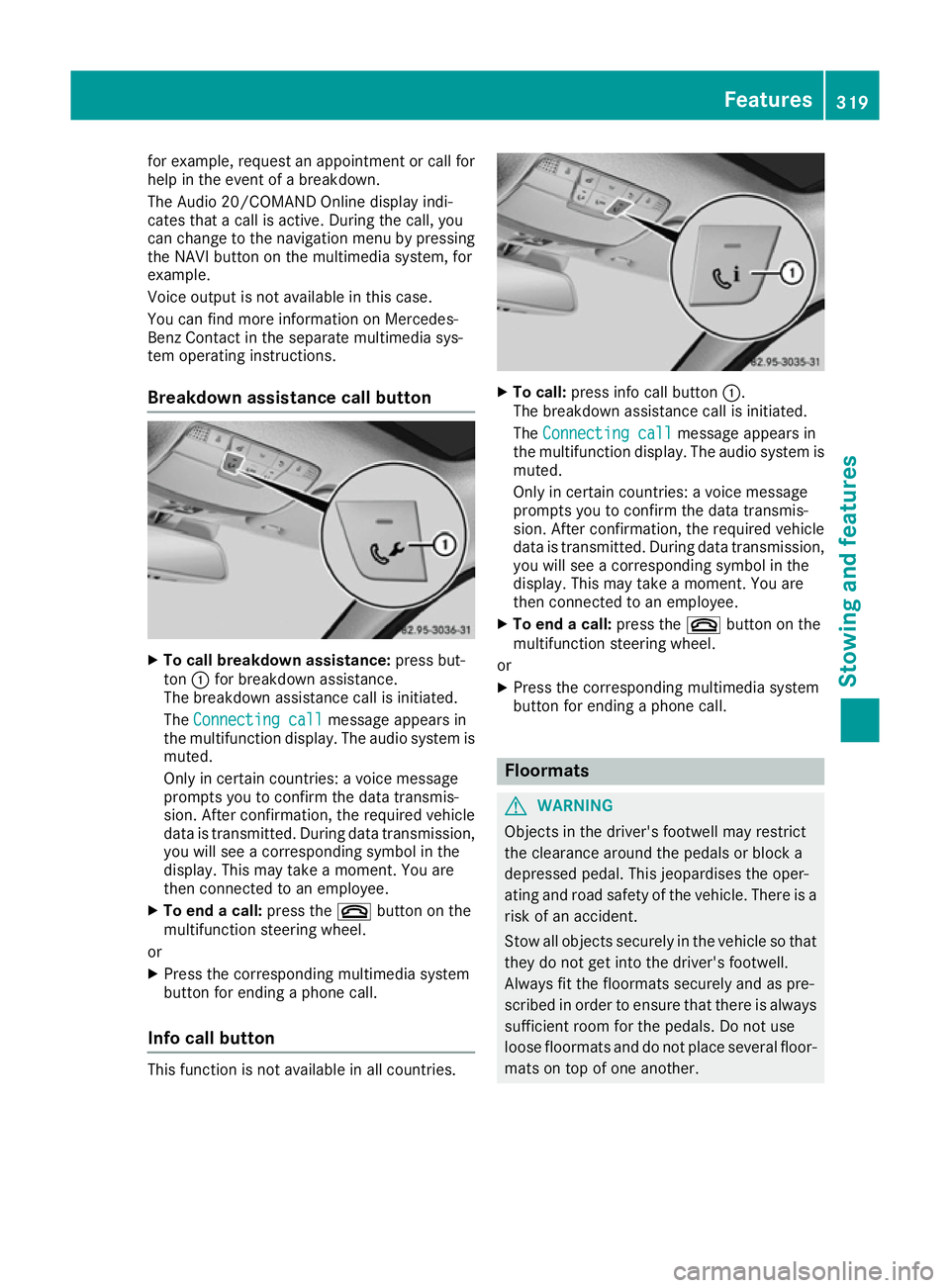
Breakdown assistance call button X
To call breakdow nassistance: press but-
ton :for breakdown assistance.
The breakdown assistance call is initiated.
The Connecting call
Connecting call message appears in
the multifunction display .The audio system is
muted.
Only in certain countries :avoice message
prompts you to confirm the data transmis-
sion. After confirmation, the required vehicle
data is transmitted. During data transmission, you wil lsee acorresponding symbol in the
display .This may take amoment. You are
then connected to an employee.
X To end acall: press the ~button on the
multifunction steering wheel.
or X Press the corresponding multimedi asystem
button for ending aphone call.
Info call button This function is not available in all countries. X
To call: press info call button :.
The breakdown assistance call is initiated.
The Connecting call Connecting call message appears in
the multifunction display .The audio syste mis
muted.
Only in certain countries :avoice message
prompts you to confirm the data transmis-
sion. After confirmation, the required vehicle
data is transmitted. During data transmission,
you wil lsee acorresponding symbol in the
display .This may take amoment. You are
then connected to an employee.
X To end acall: press the ~button on the
multifunction steering wheel.
or
X Press the corresponding multimedi asystem
button for ending aphone call. Floormats
G
WARNING
Objects in the driver's footwell may restrict
the clearance around the pedals or block a
depressed pedal. This jeopardise sthe oper-
ating and road safety of the vehicle. There is a risk of an accident.
Stow all objects securely in the vehicl esothat
they do not get into the driver's footwell.
Always fit the floormats securely and as pre-
scribe dinorder to ensure that there is always
sufficient room for the pedals. Do not use
loos efloormats and do not place severa lfloor-
mats on top of one another. Features
319Stowing and features Z
Page 330 of 385
Washing the vehiclea
nd cleaning the
paintwork
Automatic car wash G
WARNING
Braking efficiency is reduced after the vehicle has been washed .There is arisk of an acci-
dent.
After washing the vehicle, brake carefully
while paying attention to the traffic conditions in order to restore full braking efficiency.
! When DISTRONIC PLUS or the HOLD func-
tion is activated, the vehicl ebrakes automat-
ically in certain situations.
To avoi ddamage to the vehicle, deactivate
DISTRONIC PLUS and the HOLD function in
the following or similar situations:
R when towing away
R in ac ar wash
! Make sure:
R the side windows and sliding sunroo fare
close dcompletely.
R the blower for the ventilation/heating is
switched off (OFF button is depressed).
R the windscreen wiper switch is at position
0
R the 360° camera or reversing camera is
switched off.
The vehicl ecouldo therwise be damaged.
! If the key is withi
nthe rear detection range
of KEYLESS-GO, the following situations, for
example, coul dleadtot he boot lid opening
unintentionally:
R using acar wash
R using ahigh-pressure cleaner
Make sure that the key is at least 3maway
from the vehicle.
! Make sure that the automatic transmission
is in neutral position Nwhen washing your
vehicl einat ow-through car wash. The vehicle
may otherwise be damaged.
R Operating with the key:
Do not remove the key from the ignition
lock. Do not open the driver's door when
the engine is switched off or at very low
speeds. Otherwise, whe nintransmission position
Dor Rthe automatic transmission
wil lautomatically switch to park position P
and block the wheels.
R Operating with the Start/Stop button:
Do not open the driver's door whe nthe
engine is switched off or at very low
speeds. Otherwise, whe nintransmission
position Dor Rthe automatic transmission
wil lautomatically switch to park position P
and block the wheels.
Observe the following to make sure that the
automatic transmission stay sinneutral position
N:
Operating with the key and Start/Stop button:
X Make sure the ignition is switched on.
X Make sure that the vehicl eisstationary.
X Depress the brake peda land keep it
depressed.
Operating with the Start/Stop button only: X Engage park position P.
X Releas ethe brake pedal.
X Remove the Start/Stop button from the igni-
tion lock (Y page145).
X Insert the key into the ignition lock.
X Switch on the ignition.
X Depress the brake peda land keep it
depressed.
Operating with the key and Start/Stop button:
X Select neutral N.
X Releas ethe brake pedal.
X Releas ethe electric parking brake, if neces-
sary.
X Switch off the ignition and leave the key in the
ignition lock.
You can wash the vehicl einanautomatic car
wash from the very start.
Was hoff excess dirt before cleaning the vehicle
in an automatic car wash.
After using an automatic car wash, wip eoff wax
from the windscreen and the wiper blades. This
wil lprevent smears and reduce wiping noises
caused by residue on the windscreen.
Washing by hand In some countries
,washing by hand is only
allowe datspeciall yequipped washing bays. Care
327Maintenance and care Z
Page 339 of 385
Vehicl
etoolkit
General notes The towing ey
eislocate dint he stowag ewell
under the boot floor.
On vehicles with MOExtende dtyres (tyres with
run-fla tcharacteristics) the towing ey eisina
bracket under the parcel shelf.
Apart from som ecountry-specifi cvariants, vehi-
cle sare not equipped with tyre-changing tools.
if your vehicl eisequippe dwithat yre-change
tool kit, it is locate dinthe stowag ewellu nder
the boot floor.
Some tool sfor changing awheel are specifi cto
the vehicle. For more informatio nonwhich tyre
changing tool sare required and approved to
perfor mawheelchange on your vehicle, consult
aq uali fied specialist workshop.
Necessary tyre-changing tool scan include, for
example:
R Jack
R Wheel chock
R Wheel wrench
R Ratchet ring spanner
R Centring pin
i The jack weighs approximatel
y2.1 kg.
The maximu mloadb earing capacity of the
jack can be found on the adhesive labe lonthe
jack.
The jack is maintenance-free .Ifthereisa
malfunction, please contact aquali fied spe-
cialist workshop.
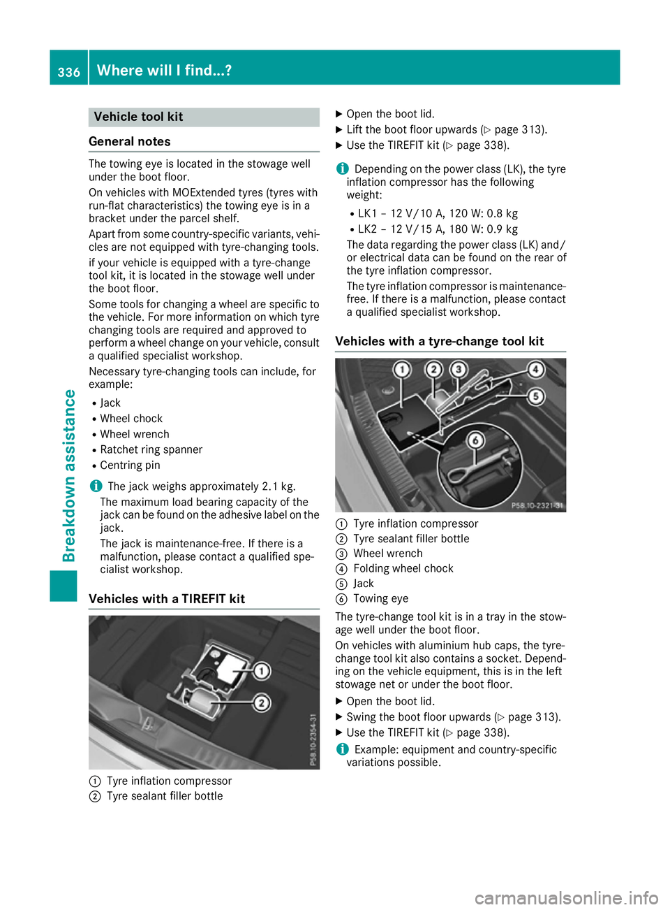
Vehicles with aTIREFI Tkit :
Tyre inflation compressor
; Tyre sealant fille rbottle X
Ope nthe boot lid.
X Lif tthe boot floor upwards (Y page 313).
X Use the TIREFIT kit (Y page 338).
i Depending on the powe rclass (LK), the tyre
inflation compressor ha sthe following
weight:
R LK1 –12V /10 A, 120 W: 0.8 kg
R LK2 –12V /15A,1 80W:0.9 kg
The data regarding the power clas s(LK) and/
or electrical data can be found on the rear of
the tyre inflation compressor.
The tyre inflation compressor is maintenance-
free. If there is amalfunction, please contact
aq ualified specialist workshop.
Vehicles with atyre-change tool kit :
Tyre inflation compressor
; Tyre sealant filler bottle
= Whee lwrench
? Folding wheel chock
A Jack
B Towing eye
The tyre-change tool kit is in atray in the stow-
age wel lunde rthe boot floor.
On vehicles with aluminium hub caps, the tyre-
change tool kit also contains asocket. Depend-
ing on the vehicle equipment, this is in the left
stowage net or unde rthe boot floor.
X Open the boot lid.
X Swing the boot floo rupwards (Y page313).
X Use the TIREFIT kit (Y page338).
i Example: equipment and country-specific
variations possible. 336
Where will
Ifind...?Breakdow nassistance
Page 340 of 385
Vehicles with MOExtende
dtyres (tyres
with run-flat characteristics) X
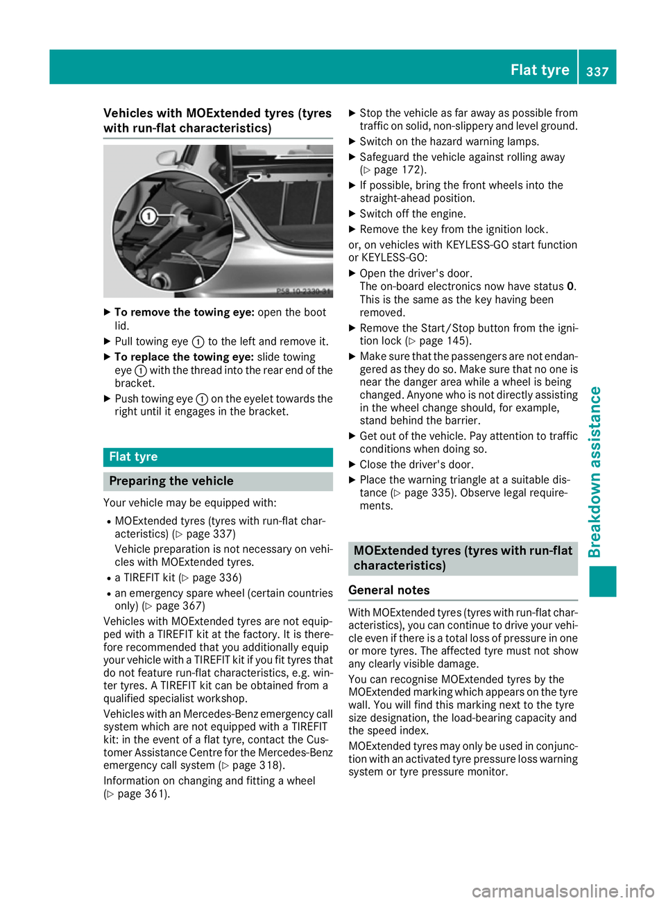
To remove the towin geye: open the boot
lid.
X Pull towing eye :to the left and remove it.
X To replace the towin geye: slidetowing
eye :with the thread into the rea rend of the
bracket.
X Push towing eye :on the eyelet toward sthe
right unti litengages in the bracket. Flat tyre
Preparin
gthe vehicle
Your vehicl emay be equipped with:
R MOExtende dtyres (tyres with run-fla tchar-
acteristics )(Ypage 337)
Vehicl epreparation is not necessary on vehi-
cle sw ithM OExtende dtyres.
R aT IREFIT kit (Y page 336)
R an emergency spare whee l(certai ncountries
only) (Y page 367)
Vehicles with MOExtende dtyres are not equip-
pe dw ithaT IREFIT kit at the factory .Itisthere-
fore recommende dthaty ou additionally equip
your vehicl ewithaT IREFIT kit if yo ufit tyres that
do not feature run-fla tcharacteristics, e.g .win-
ter tyres. ATIREFIT kit can be obtained from a
qualified specialist workshop.
Vehicles with an Mercedes-Benz emergency call
system which are not equipped with aTIREFIT
kit: in the event of aflatt yre, contact the Cus-
tome rAssistance Centre for the Mercedes-Benz
emergency cal lsystem (Y page 318).
Informatio nonchanging and fitting awheel
( Y page 361). X
Stop the vehicl easfar away as possibl efrom
traffic on solid ,non-slippery and level ground.
X Switch on the hazard warning lamps.
X Safeguard the vehicl eagain st rolling away
(Y page 172).
X If possible, bring the front wheels into the
straight-ahea dposition.
X Switch off the engine.
X Remove the key from the ignition lock.
or, on vehicles with KEYLESS-GO start function
or KEYLESS ‑GO:
X Ope nthe driver' sdoor.
The on-board electronics now have status 0.
Thi sist he same as the key having been
removed.
X Remove the Start/Stop button from the igni-
tio nlock( Ypage 145).
X Make sure tha tthe passenger sare not endan-
gered as they do so. Make sure tha tnoone is
nea rthe danger are awhile awheel is being
changed .Anyone wh oisnot directl yassis ting
in the whee lchange should, for example,
stand behind the barrier.
X Ge toutof the vehicle. Pa yattentio ntotraffic
conditions when doing so.
X Close the driver' sdoor.
X Place the warning triangl eatasuitabl edis-
tance (Y page 335). Observe lega lrequire-
ments. MOExtende
dtyres (tyres with run-flat
characteristics)
General notes With MOExtende
dtyres (tyres with run-fla tchar-
acteristics), yo ucan continue to drive your vehi-
cle eve nifthereisat otallos sofp ressure in one
or more tyres. The affecte dtyrem ustn ot show
any clearl yvisible damage.
Yo uc an recognise MOExtende dtyres by the
MOExtende dmarking which appears on the tyre
wall .You will find thi smarking next to the tyre
size designation, the load-bearing capacity and
the speed index.
MOExtende dtyres ma yonlybeu sedinc onjunc-
tio nw ithana ctivate dtyrep ressure loss warning
system or tyr epressure monitor. Flat tyre
337Breakdown assis tance
Page 350 of 385
X
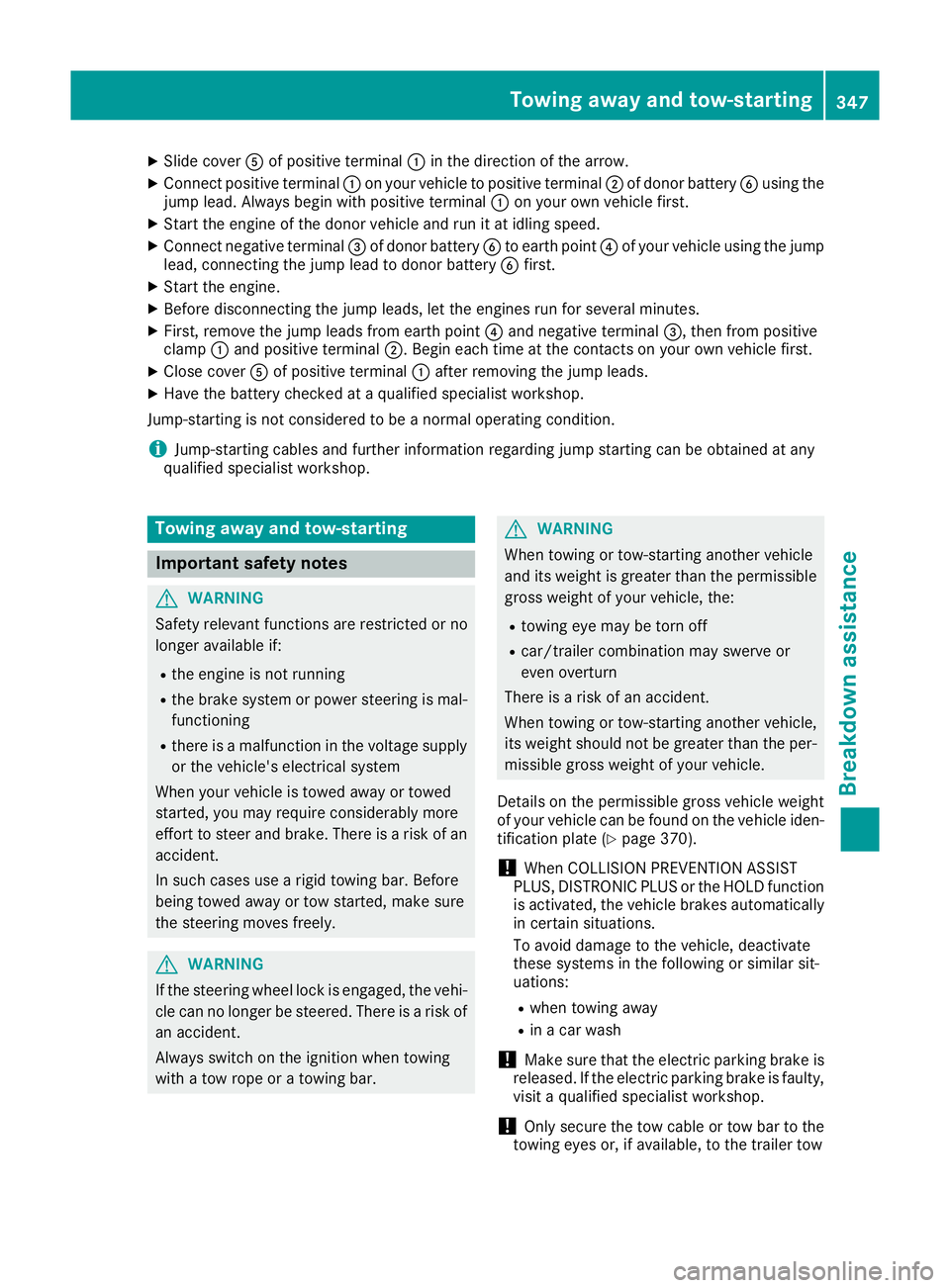
Slide cover Aof positive terminal :in the direction of the arrow.
X Connect positive terminal :on your vehicl etopositive terminal ;of dono rbattery Busing the
jump lead .Alway sbegin with positive terminal :on your ow nvehicl efirst.
X Start the engine of the dono rvehicl eand run it at idling speed.
X Connect negative terminal =of dono rbattery Bto earth point ?of your vehicl eusing the jump
lead ,connecting the jump lead to dono rbattery Bfirst.
X Start the engine.
X Before disconnecting the jump leads, le tthe engines run for several minutes.
X First, remove the jump lead sfrom earth point ?and negative terminal =,then from positive
clamp :and positive terminal ;.Begine acht ime at the contacts on your ow nvehicl efirst.
X Close cover Aof positive terminal :afte rremoving the jump leads.
X Have the battery checke dataqualified specialist workshop.
Jump-starting is not considered to be anorma loperating condition.
i Jump-starting cable
sand further information regarding jump starting can be obtaine datany
qualified specialist workshop. Towin
gawayand tow-starting Important safety notes
G
WARNING
Safety relevant functions are restricted or no
longer available if:
R the engine is not running
R the brake system or power steering is mal-
functioning
R there is amalfunction in the voltag esupply
or the vehicle's electrical system
Whe nyourv ehicl eist owedawayort owed
started, yo umay require considerably more
effort to stee rand brake. There is ariskofan
accident.
In such cases us earigid towing bar. Before
being towe dawayort ow started, make sure
the steering move sfreely. G
WARNING
If the steering wheel lock is engaged ,the vehi-
cle can no longer be steered .There is ariskof
an accident.
Alway sswitch on the ignition when towing
with atow rop eorat owing bar. G
WARNING
Whe ntowing or tow-starting another vehicle
and its weigh tisg reate rthan the permissible
gross weight of your vehicle, the:
R towing ey emay be torn off
R car/traile rcombination may swerve or
eve noverturn
There is ariskofana ccident.
Whe ntowing or tow-starting another vehicle,
its weight shoul dnot be greate rthan the per-
missible gross weight of your vehicle.
Details on the permissible gross vehicl eweight
of your vehicl ecan be found on the vehicl eide n-
tification plate (Y page 370).
! Whe
nCOLLISIO NPREVENTION ASSIST
PLUS, DISTRONIC PLU Sorthe HOLD function
is activated, the vehicl ebrakes automatically
in certain situations.
To avoid damag etothe vehicle, deactivate
thes esystems in the following or similar sit-
uations:
R when towing away
R in ac ar wash
! Make sure that the electri
cparking brake is
released .Ifthe electri cparking brake is faulty,
visit aquali fied specialist workshop.
! Only secure the tow cable or tow ba
rtothe
towing eyes or, if available ,tothe traile rtow Towin
gawayand tow-starting
347Breakdown assistance Z
Page 351 of 385
hitch. You could otherwise damage the vehi-
cle.
! Observe the following points when towing
with atow rope:
R Secure the tow rope on the same side on
both vehicles.
R Make sure that the tow rope is not longer
than legallyp ermitted. Mark the tow rope in
the middle, e.g. with awhite cloth
(30 x30c m).This will make other road
users aware that avehicle is being towed.
R Only secure the tow cable to the towing
eyes or, if available, to the trailer tow hitch.
R Observe the brake lamps of the towing
vehicle while driving. Always maintain adis-
tance adistance so that the tow rope does
not sag.
R Do not use steel cables or chains to tow
your vehicle. You could otherwise damage
the vehicle.
! Do not use the trailer tow hitch for recovery
or towing. Do not use the towing eye for
recovery. This could damage the vehicle. If in doubt, have the vehicle recovered using a
crane.
! Pull away smoothly when towing away or
tow-starting avehicle. If the tractive power is
too high, the vehicles could be damaged.
! Shift the automatic transmission to
Nand
do not open the driver's or front passenger's
door during towing. The automatic transmis-
sion may otherwise shift to position P,which
could damage the transmission.
! You may tow the vehicle for
amaximum of
50km.At owing speed of 50 km/h must not
be exceeded.
For towing distances over 50 km, the entire
vehicle must be lifted up and transported.
Observe the legal requirements for the relevant countries when towing.
It is better to have the vehicle transported than
to have it towed.
If the vehicle has suffered transmission damage,
have it transported on atransporter or trailer.
Vehicles with automatic transmission: when
towing avehicle, the automatic transmission
must be in position N.Ifthe automatic trans-
mission cannot be shifted to position N,have the vehicle transported on
atransporter or
trailer.
The battery must be connected and charged.
Otherwise, you:
R cannot turn the key to position 2in the igni-
tion lock
R cannot release the electric parking brake
R cannot shift the transmission to position Non
vehicles with automatic transmission
Deactivate the automatic locking feature before towing the vehicle (Y page 88). You could oth-
erwise be locked out when pushing or towing
the vehicle.
Deactivate tow-away protection before the vehi- cle is towed away (Y page 79). Fitting/removing the towing eye
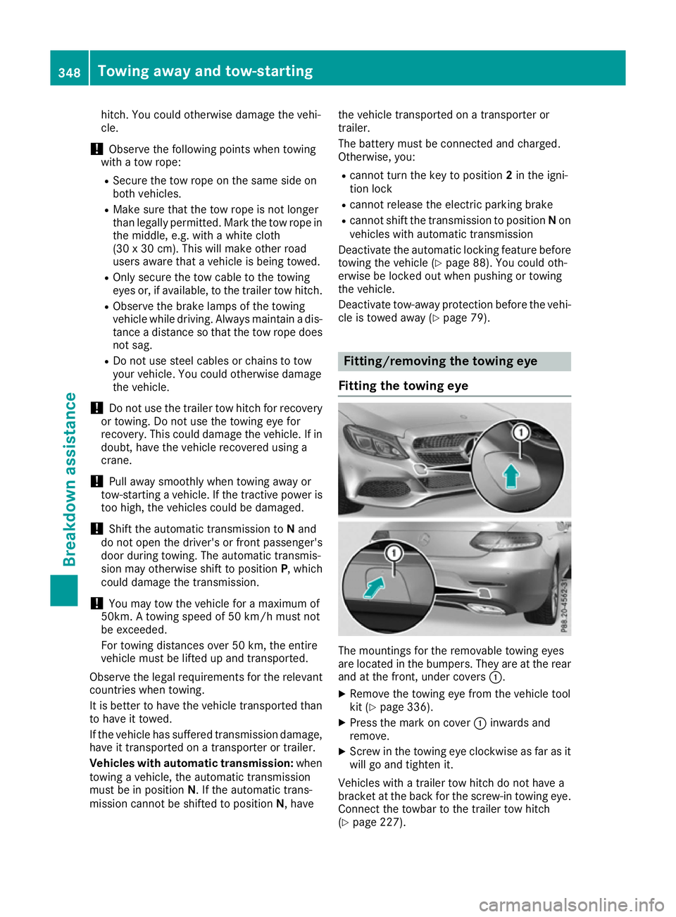
Fitting the towing eye The mountings for the removable towing eyes
are located in the bumpers. They are at the rear
and at the front,u nder covers:.
X Remove the towing eye from the vehicle tool
kit (Y page 336).
X Press the mark on cover :inwards and
remove.
X Screw in the towing eye clockwise as far as it
will go and tighten it.
Vehicles with atrailer tow hitch do not have a
bracket at the back for the screw-in towing eye. Connect the towbar to the trailer tow hitch
(Y page 227). 348
Towing away and tow-startingBreakdown assistance