lock MERCEDES-BENZ C-CLASS SALOON 2007 Owners Manual
[x] Cancel search | Manufacturer: MERCEDES-BENZ, Model Year: 2007, Model line: C-CLASS SALOON, Model: MERCEDES-BENZ C-CLASS SALOON 2007Pages: 377, PDF Size: 6.19 MB
Page 224 of 377

Trailer towing*
22
1 Saloon
1
Handl e
2 Cove r Estate
1
Handl e
2 Cove r X
To open: turn handle 1anti-clockwise.
X Fold cover 2down. 1
Indicator lamp
2 Release wheel for the trailer tow hitch
X Pull out release wheel 2.
X Turn release wheel 2anti-clockwise.
The ball coupling disengages and folds out
from under the rear bumper. Indicator lamp
1 flashes. X
Press the ball coupling in the direction of
the arrow by hand until it engages in a ver-
tical position.
Indicator lamp 1goes out. The power
socket folds away automatically.
Vehicles with a 4-button multi-function
steering wheel: the messageTrailer
hitch Check lock mech. is shown in the
multi-function display until the ball cou-
pling has engaged.
Vehicles with a luxury multi-function
steering wheel* (12 buttons): the mes-
sage Trailer hitch Check lock
mech. is shown in the multi-function dis-
play until the ball coupling is engaged.
X Make sure that the ball of the ball coupling
is clean and that, depending on the trailer Operation
* optional
204_AKB; 2; 3, en-GB
mkalafa,
2007-06-26T23:11:51+02:00 - Seite 221 Z
Page 227 of 377
Trailer towing*
22
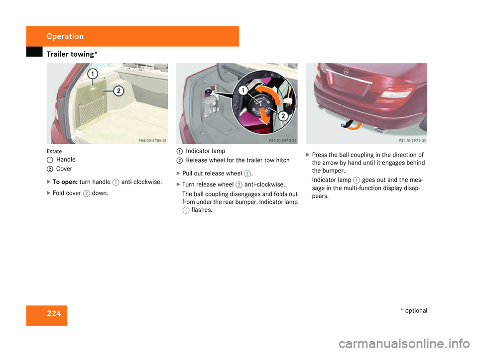
4 Estate
1
Handl e
2 Cove r
X To open: turn handle 1anti-clockwise.
X Fold cover 2down. 1
Indicator lamp
2 Release wheel for the trailer tow hitch
X Pull out release wheel 2.
X Turn release wheel 2anti-clockwise.
The ball coupling disengages and folds out
from under the rear bumper. Indicator lamp
1 flashes. X
Press the ball coupling in the direction of
the arrow by hand until it engages behind
the bumper.
Indicator lamp 1goes out and the mes-
sage in the multi-function display disap-
pears. Operation
* optional
204_AKB; 2; 3, en-GB
mkalafa,
2007-06-26T23:11:51+02:00 - Seite 224
Page 228 of 377
Trailer towing*
22
5 Trailer power suppl
y
When delivered from the factory, your vehi-
cle's trailer socket outlet is equipped with a
permanent power supply and a power supply
that is switched on via the ignition lock .
The permanent power supply is supplied via
trailer socket pin 9.
The power supply that is switched on via the
ignition lock is supplied via trailer socket pin
10.
! You can connect consumers with a power
rating of up to 240 W to the permanen t
power supply and up to 180 W to the power
supply that is switched on via the ignition
lock .
You must not charge a trailer battery using
the power supply.
You can obtain further information about
installing the trailer electrics from a qualified
specialist workshop, e.g. a Mercedes-Ben z
Service Centre.
X To switch the switched power supply on
or off: turn the key in the ignition lock to
position 2or 0, respectively. Trailer with 7-pin connector
If your trailer has a 7-pin connector, you can
connect it to the 13-pin socket on the ball
coupling using an adapter or, if necessary, an
adapter cable. Both of these can be obtained
at a qualified specialist workshop, e.g. at a
Mercedes-Benz Service Centre.
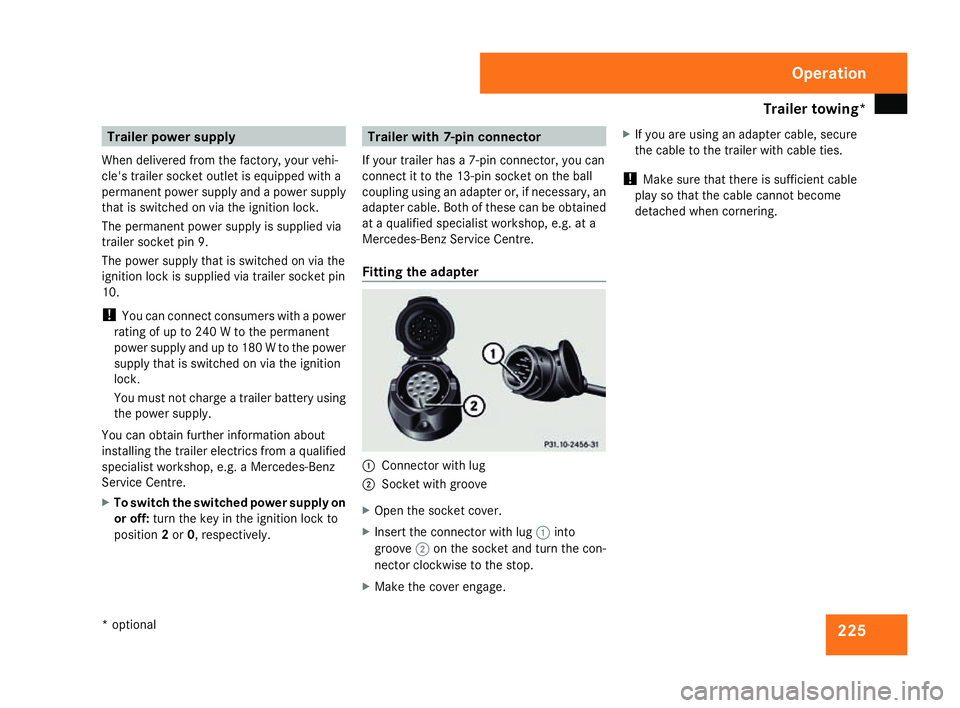
Fitting the adapter 1
Connector with lug
2 Socket with groove
X Open the socket cover.
X Insert the connector with lug 1into
groove 2on the socket and turn the con-
nector clockwise to the stop.
X Make the cover engage. X
If you are using an adapter cable, secure
the cable to the trailer with cable ties.
! Make sure that there is sufficient cable
play so that the cable cannot become
detached when cornering. Operation
* optional
204_AKB; 2; 3, en-GB
mkalafa
, 2007-06-26T23:11:51+02:00 - Seite 225
Page 231 of 377
Car
e 228
High-pressure cleaners G
Risk of accident
Do not use high-pressure cleaners with cir-
cular-jet nozzles (dirt grinders) to clean
your vehicle or - especially - the tyres. Yo u
could otherwise damage the tyres and
cause an accident.
! Observe the instructions issued by the
equipment manufacturer concerning the
distance to be maintained between the
nozzle of the high-pressure cleaner and the
vehicle (at least 30 cm).
Move the high-pressure cleaner nozzle
around when cleaning your vehicle .
Do not aim directly at any of the following:
R Tyres
R Door joint
R Electrical components
R Batter y
R Connectors
R Bulbs
R Seals
Damaged seals or electrical components
can lead to failures or leaks .Cleaning the wiper blades and the out
-
side of the windscreen G
Risk of injury
Turn the key to position 0in the ignition
lock before cleaning the windscreen or the
wiper blades. There is otherwise a risk of
the windscreen wipers being set in motion
and causing injury.
! Only fold the windscreen wipers away
from the windscreen when vertical, other-
wise you will damage the bonnet.
X Fold the wiper arms away from the wind-
screen until you feel them engage.
X Clean the windscreen and the wiper blades .
X Fold the windscreen wipers back agai n
before the ignition is switched on.
! Do not clean the wiper blades too often,
as otherwise the coating may come off.
This could cause wiper noise.
Cleaning the windows !
Do not use dry cloths, abrasive products,
solvents or cleaning agents containing sol-
vents to clean the inside of the windows. Clean the insides of the windows with
a
damp cloth or commercially-available glass
cleaner. Avoid touching the inside of the
rear windscreen and the side windows with
hard objects, e.g. ice scrapers or rings. You
could otherwise cause damage to the win-
dows, rear window heating or aerial on the
rear window.
i Anti-glare film retrofitted to the insides of
the windows could interfere with radio or
mobile phone reception, especially if it is
conductive or metal-coated film. Informa -
tion about anti-glare film can be obtained
from any Mercedes-Benz Service Centre.
Cleaning the headlamps X
Clean the headlamp lenses with a wet
sponge.
! Only use washer fluid which is suitable
for plastic lenses. Unsuitable washer fluid
could damage the plastic lenses of th e
headlamps.
Therefore, do not use the following:
R Dry cloths
R Abrasive cleaning agents Operatio
n
204_AKB; 2; 3, en-GB
mkalafa,
2007-06-26T23:11:51+02:00 - Seite 228
Page 234 of 377
231
Where will I find...?
...........................232
Display messages ............................. 236
Troubleshooting ................................ 276
Locking/unlocking in an emer-
gency ................................................. 300
Resetting triggered NECK-PRO
head restraints .................................. 303
Changing the batteries .....................304
Changing the bulbs ...........................305
Replacing the wiper blades ..............312
Flat tyre ............................................. 313
Battery ............................................... 324
Jump-starting .................................... 328
Towing and tow-starting ..................329
Fuses .................................................. 332 Practical advice
204_AKB; 2; 3, en-GB
mkalafa,
2007-06-26T23:11:51+02:00 - Seite 231
Page 235 of 377
Where will I find...?
232 Where will I find...?
Warning triangle
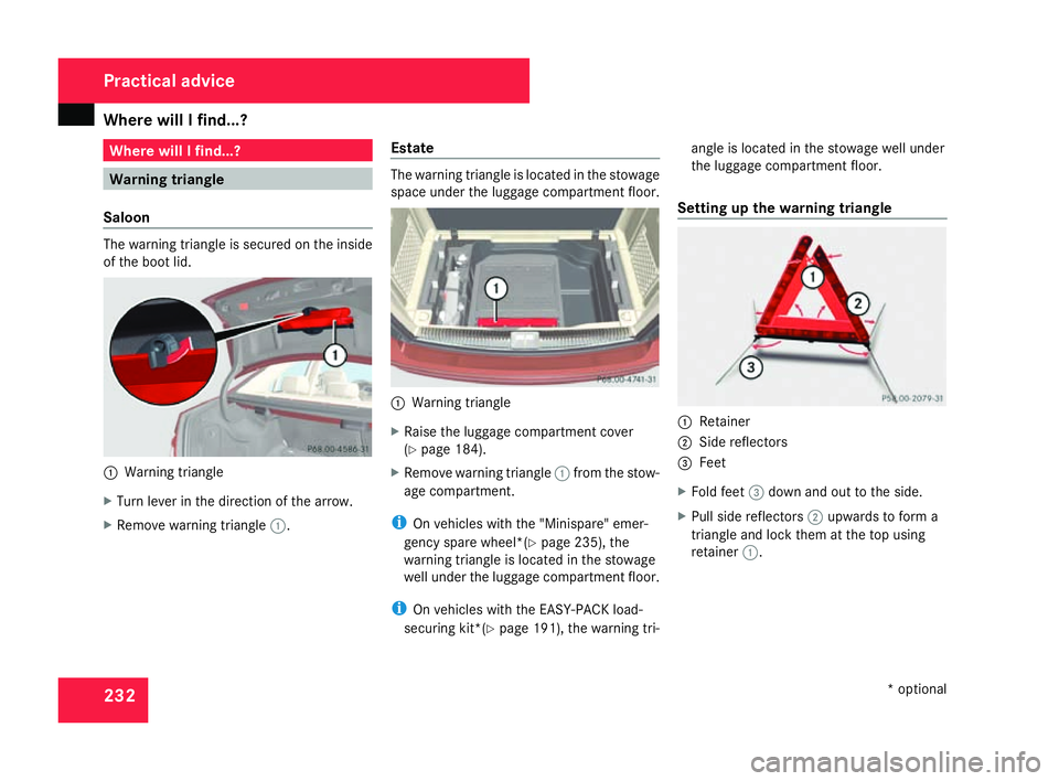
Saloon The warning triangle is secured on the insid
e
of the boot lid. 1
Warning triangle
X Turn lever in the direction of the arrow.
X Remove warning triangle 1. Estat
e The warning triangle is located in the stowage
space under the luggage compartment floor.
1
Warning triangle
X Raise the luggage compartment cover
(Y page 184).
X Remove warning triangle 1from the stow-
age compartment.
i On vehicles with the "Minispare" emer-
gency spare wheel*(Y page 235), the
warning triangle is located in the stowage
well under the luggage compartment floor.
i On vehicles with the EASY-PACK load-
securing kit*( Ypage 191), the warning tri- angle is located in the stowage well under
the luggage compartment floor.
Setting up the warning triangle 1
Retainer
2 Side reflector s
3 Feet
X Fold feet 3down and out to the side.
X Pull side reflectors 2upwards to form a
triangle and lock them at the top using
retainer 1. Practical advice
* optional
204_AKB; 2; 3, en-GB
mkalafa,
2007-06-26T23:11:51+02:00 - Seite 232
Page 236 of 377

Where will I find...?
233First-aid kit
i Check the expiry dates of the first-aid kit
contents annually, and replace them if nec-
essary.
Saloon Depending on the vehicle's equipment, th
e
first-aid kit is located either in the boot in the
open storage compartment or behind the
cover on the left side .1
Rotary catch
2 Cove r
X To open: turn handle 1anti-clockwise.
X Fold down cover 2. Estat
e The first-aid kit is located in the luggage com-
partment behind the cover to the right in the
direction of travel.
1
Handl e
X To open: pull handle 1.
X Fold down cover . 1
First-aid kit
X Remove first-aid kit 1. Fire extinguisher*
i Have the fire extinguisher refilled after
each use and checked every one or two
years. Otherwise, it may fail in an emer -
gency.
Observe the legal requirements in all coun-
tries concerned. Practical advice
* optional
204_AKB; 2; 3, en-GB
mkalafa,
2007-06-26T23:11:51+02:00 - Seite 233
Page 237 of 377
Where will I find...?
234
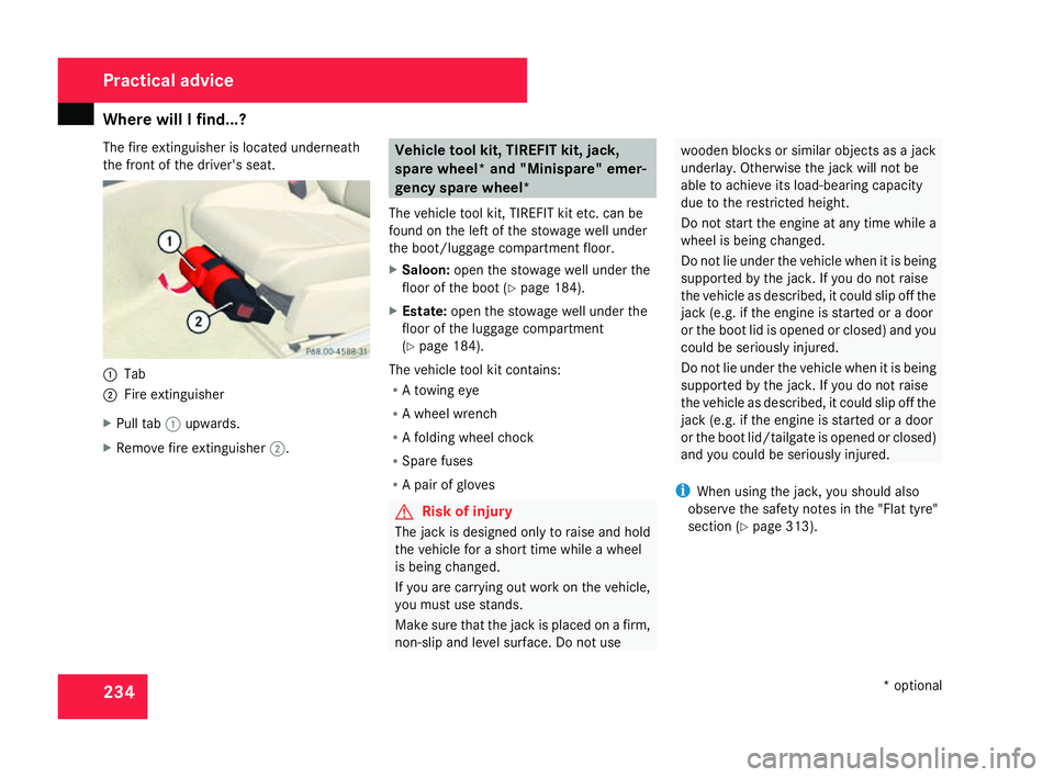
The fire extinguisher is located underneath
the front of the driver's seat.
1
Tab
2 Fire extinguishe r
X Pull tab 1upwards.
X Remove fire extinguisher 2. Vehicle tool kit, TIREFIT kit, jack
,
spare wheel* and "Minispare" emer-
gency spare wheel*
The vehicle tool kit, TIREFIT kit etc. can be
found on the left of the stowage well under
the boot/luggage compartment floor.
X Saloon: open the stowage well under the
floor of the boot (Y page 184).
X Estate: open the stowage well under th e
floor of the luggage compartment
( Y page 184).
The vehicle tool kit contains :
R A towing ey e
R A wheel wrench
R A folding wheel chock
R Spare fuses
R A pair of glove s G
Risk of injury
The jack is designed only to raise and hol d
the vehicle for a short time while a whee l
is being changed.
If you are carrying out work on the vehicle,
you must use stands.
Make sure that the jack is placed on a firm ,
non-slip and level surface. Do not us e wooden blocks or similar objects as a jac
k
underlay. Otherwise the jack will not be
able to achieve its load-bearing capacit y
due to the restricted height.
Do not start the engine at any time while a
wheel is being changed.
Do not lie under the vehicle when it is bein g
supported by the jack. If you do not raise
the vehicle as described, it could slip off the
jack (e.g. if the engine is started or a door
or the boot lid is opened or closed) and you
could be seriously injured.
Do not lie under the vehicle when it is being
supported by the jack. If you do not raise
the vehicle as described, it could slip off the
jack (e.g. if the engine is started or a door
or the boot lid/tailgate is opened or closed)
and you could be seriously injured.
i When using the jack, you should also
observe the safety notes in the "Flat tyre"
section (Y page 313). Practical advice
* optional
204_AKB; 2; 3, en-GB
mkalafa,
2007-06-26T23:11:51+02:00 - Seite 234
Page 238 of 377
Where will I find...?
235
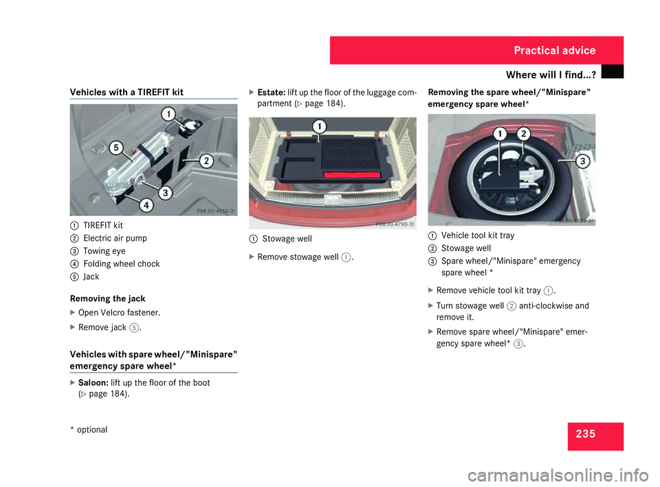
Vehicles with a TIREFIT kit
1
TIREFIT kit
2 Electric air pump
3 Towing eye
4 Folding wheel chock
5 Jack
Removing the jack
X Open Velcro fastener.
X Remove jack 5.
Vehicles with spare wheel/"Minispare "
emergency spare wheel* X
Saloon: lift up the floor of the boot
( Y page 184). X
Estate: lift up the floor of the luggage com -
partment (Y page 184). 1
Stowage well
X Remove stowage well 1. Removing the spare wheel/"Minispare"
emergency spare wheel
* 1
Vehicle tool kit tray
2 Stowage well
3 Spare wheel/"Minispare" emergency
spare wheel *
X Remove vehicle tool kit tray 1.
X Turn stowage well 2anti-clockwise and
remove it.
X Remove spare wheel/"Minispare" emer-
gency spare wheel* 3. Practical advice
* optional
204_AKB; 2; 3, en-GB
mkalafa,
2007-06-26T23:11:51+02:00 - Seite 235
Page 240 of 377
Display
messages 23
7 cator lamps, display messages or system
failures. The vehicle's handling character-
istics may be affected. Adjust your driving
style and speed accordingly .
Immediately consult a qualified specialist
workshop which has the necessary special-
ist knowledge and tools to carry out the
work required. Mercedes-Benz recom-
mends that you use a Mercedes-Benz
Service Centre for this purpose. In particu- lar, work relevant to safety or on safety-
related systems must be carried out at
a
qualified specialist workshop.
Before starting a journey, check that the
warning and indicator lamps are operatin g
correctly .
X Turn the key to position 2in the ignition
lock .
or X
Press the KEYLESS GO button* twice.
All warning and indicator lamps (except for
the main-beam indicator lamp and the turn
signal indicator lamps) light up and the
multi-function display is activated.
The following tables contain all the display
messages. To make it easier for you to find
the relevant display message, the display
messages are divided into text messages
( Y page 237) and symbol messages
( Y page 247). Text messages
G
Risk of accident and injury
Always have maintenance work carried out at a qualified specialist workshop which has the necessary specialist knowledge and tools to
carry out the work required .
Mercedes-Benz recommends that you use a Mercedes-Benz Service Centre for this purpose.
In particular, work relevant to safety or on safety-related systems must be carried out at a qualified specialist workshop. The operating
safety of the vehicle can be affected if this work is carried out incorrectly. There is a risk of accident and injury.
Vehicles with 4-button multi-function steering wheel: text messages are listed in the left-hand column under "Display messages".
Vehicles with 12-button luxury multi-function steering wheel: text messages are listed in the right-hand column under "Display mes-
sages". Practical advice
* optional
204_AKB; 2; 3, en-GB
mkalafa,
2007-06-26T23:11:51+02:00 - Seite 237