MERCEDES-BENZ G-Class 2009 W463 Owner's Manual
Manufacturer: MERCEDES-BENZ, Model Year: 2009, Model line: G-Class, Model: MERCEDES-BENZ G-Class 2009 W463Pages: 264, PDF Size: 6.98 MB
Page 131 of 264
Never place hands under seat or near any
moving parts while a seat is being adjusted.
For safety reasons, the rear seat bench must
only be adjusted when the vehicle is
stationary.
Never drive a vehicle with the tailgate open.
Deadly carbon monoxide (CO) gases may
enter vehicle interior resulting in
unconsciousness and death.
! Before folding the rear seat backrest and
the rear seat bench forward, make sure
that all containers in the rear cup holder are
removed.
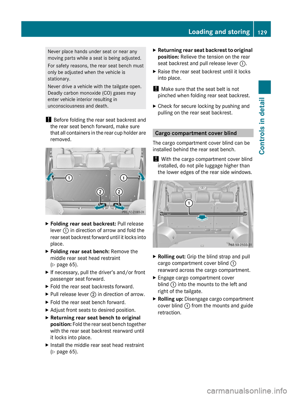
XFolding rear seat backrest: Pull release
lever : in direction of arrow and fold the
rear seat backrest forward until it locks into
place.
XFolding rear seat bench: Remove the
middle rear seat head restraint
(Y page 65).
XIf necessary, pull the driver’s and/or front
passenger seat forward.
XFold the rear seat backrests forward.XPull release lever ; in direction of arrow.XFold the rear seat bench forward.XAdjust front seats to desired position.XReturning rear seat bench to original
position: Fold the rear seat bench together
with the rear seat backrest rearward until
it locks into place.
XInstall the middle rear seat head restraint
(Y page 65).
XReturning rear seat backrest to original
position: Relieve the tension on the rear
seat backrest and pull release lever :.
XRaise the rear seat backrest until it locks
into place.
! Make sure that the seat belt is not
pinched when folding rear seat backrest.
XCheck for secure locking by pushing and
pulling on the rear seat backrest.
Cargo compartment cover blind
The cargo compartment cover blind can be
installed behind the rear seat bench.
! With the cargo compartment cover blind
installed, do not pile luggage higher than
the lower edges of the rear side windows.
XRolling out: Grip the blind strap and pull
cargo compartment cover blind :
rearward across the cargo compartment.
XEngage cargo compartment cover
blind : into the mounts to the left and
right of the tailgate.
XRolling up: Disengage cargo compartment
cover blind : from the mounts and guide
retraction.
Loading and storing129Controls in detail463_AKB; 2; 52, en-USd2ureepe,Version: 2.11.7.12008-12-02T10:52:11+01:00 - Seite 129Z
Page 132 of 264
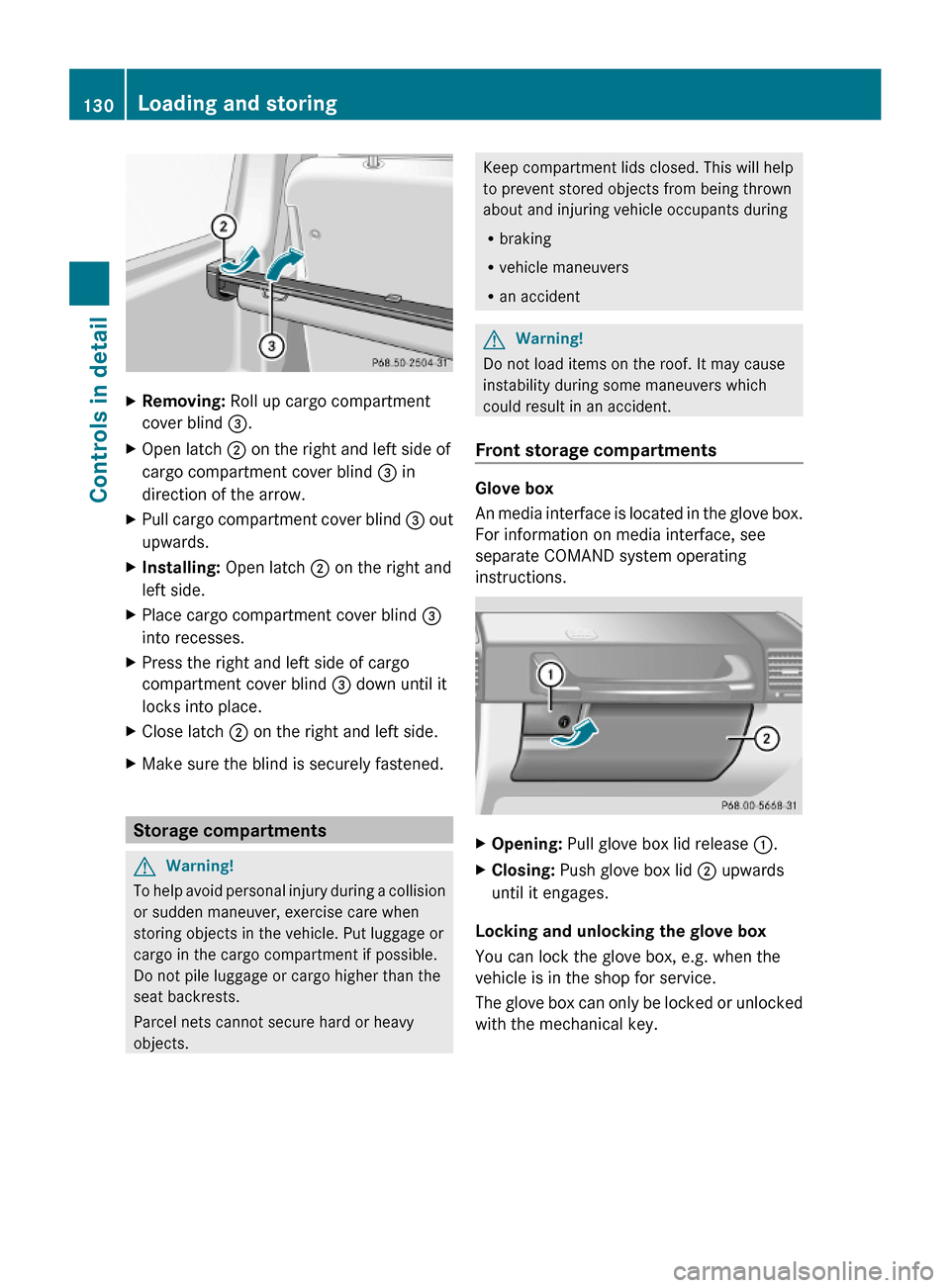
XRemoving: Roll up cargo compartment
cover blind =.
XOpen latch ; on the right and left side of
cargo compartment cover blind = in
direction of the arrow.
XPull cargo compartment cover blind = out
upwards.
XInstalling: Open latch ; on the right and
left side.
XPlace cargo compartment cover blind =
into recesses.
XPress the right and left side of cargo
compartment cover blind = down until it
locks into place.
XClose latch ; on the right and left side.XMake sure the blind is securely fastened.
Storage compartments
GWarning!
To help avoid personal injury during a collision
or sudden maneuver, exercise care when
storing objects in the vehicle. Put luggage or
cargo in the cargo compartment if possible.
Do not pile luggage or cargo higher than the
seat backrests.
Parcel nets cannot secure hard or heavy
objects.
Keep compartment lids closed. This will help
to prevent stored objects from being thrown
about and injuring vehicle occupants during
Rbraking
Rvehicle maneuvers
Ran accident
GWarning!
Do not load items on the roof. It may cause
instability during some maneuvers which
could result in an accident.
Front storage compartments
Glove box
An media interface is located in the glove box.
For information on media interface, see
separate COMAND system operating
instructions.
XOpening: Pull glove box lid release :.XClosing: Push glove box lid ; upwards
until it engages.
Locking and unlocking the glove box
You can lock the glove box, e.g. when the
vehicle is in the shop for service.
The glove box can only be locked or unlocked
with the mechanical key.
130Loading and storingControls in detail
463_AKB; 2; 52, en-USd2ureepe,Version: 2.11.7.12008-12-02T10:52:11+01:00 - Seite 130
Page 133 of 264
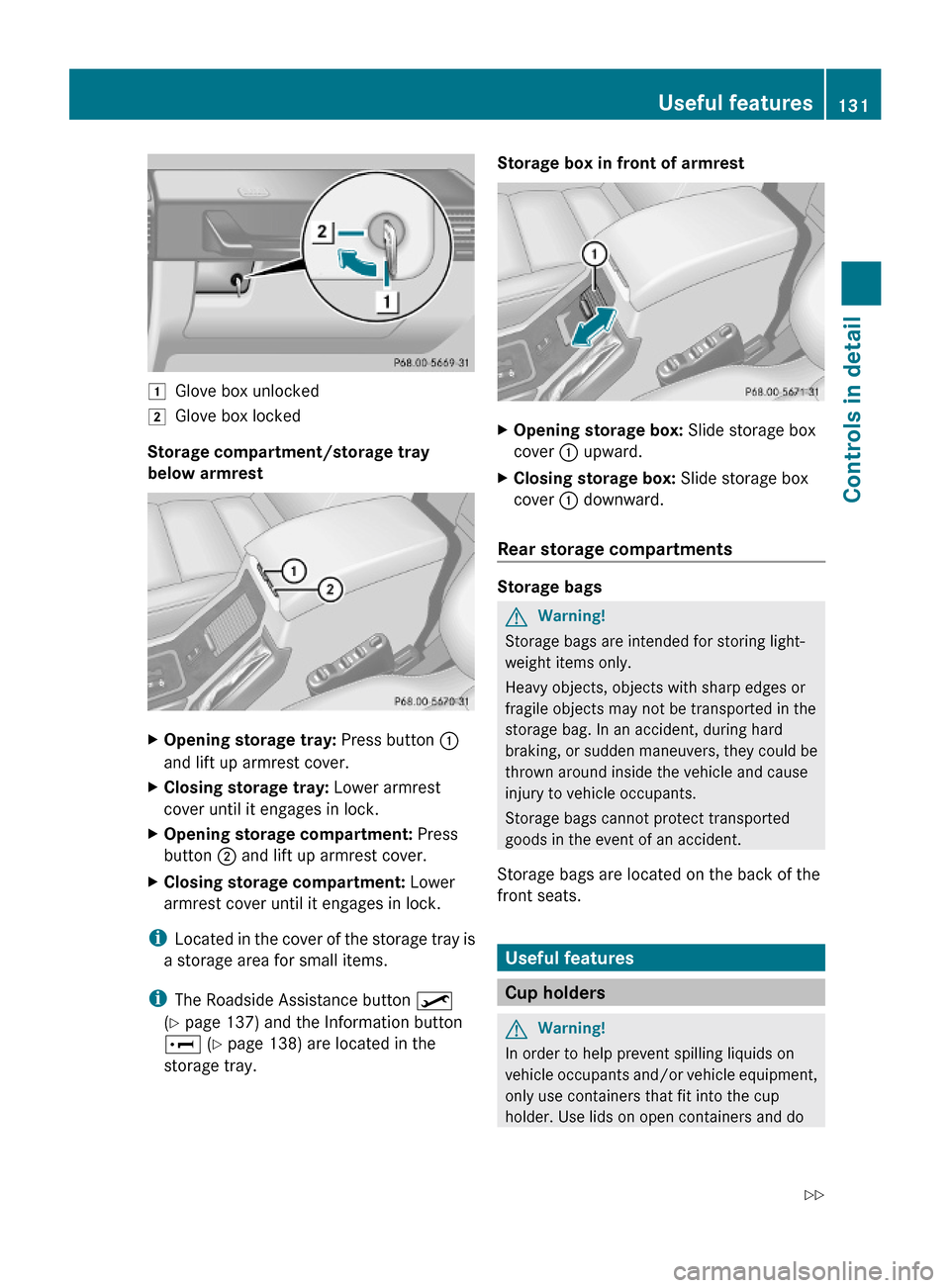
1Glove box unlocked2Glove box locked
Storage compartment/storage tray
below armrest
XOpening storage tray: Press button :
and lift up armrest cover.
XClosing storage tray: Lower armrest
cover until it engages in lock.
XOpening storage compartment: Press
button ; and lift up armrest cover.
XClosing storage compartment: Lower
armrest cover until it engages in lock.
iLocated in the cover of the storage tray is
a storage area for small items.
iThe Roadside Assistance button º
(Y page 137) and the Information button
E (Y page 138) are located in the
storage tray.
Storage box in front of armrestXOpening storage box: Slide storage box
cover : upward.
XClosing storage box: Slide storage box
cover : downward.
Rear storage compartments
Storage bags
GWarning!
Storage bags are intended for storing light-
weight items only.
Heavy objects, objects with sharp edges or
fragile objects may not be transported in the
storage bag. In an accident, during hard
braking, or sudden maneuvers, they could be
thrown around inside the vehicle and cause
injury to vehicle occupants.
Storage bags cannot protect transported
goods in the event of an accident.
Storage bags are located on the back of the
front seats.
Useful features
Cup holders
GWarning!
In order to help prevent spilling liquids on
vehicle occupants and/or vehicle equipment,
only use containers that fit into the cup
holder. Use lids on open containers and do
Useful features131Controls in detail463_AKB; 2; 52, en-USd2ureepe,Version: 2.11.7.12008-12-02T10:52:11+01:00 - Seite 131Z
Page 134 of 264
not fill containers to a height where the
contents, especially hot liquids, could spill
during braking, vehicle maneuvers, or in an
accident. Liquids spilled on vehicle occupants
may cause serious personal injury. Liquids
spilled on vehicle equipment may cause
damage not covered by the Mercedes-Benz
Limited Warranty.
When not in use, keep the cup holder closed.
An open cup holder may cause injury to you
or others when contacted during braking,
vehicle maneuvers, or in an accident.
Keep in mind that objects placed in the cup
holder may come loose during braking,
vehicle maneuvers, or in an accident and be
thrown around in the vehicle interior. Objects
thrown around in the vehicle interior may
cause an accident and/or serious personal
injury.
Cup holder next to armrest
XPlace bracket of cup holder : into recess
indicated by arrow of cup holder base ;.
If the cup holder is no longer in use, it can for
example, be stored in the glove box or storage
compartment below the armrest.
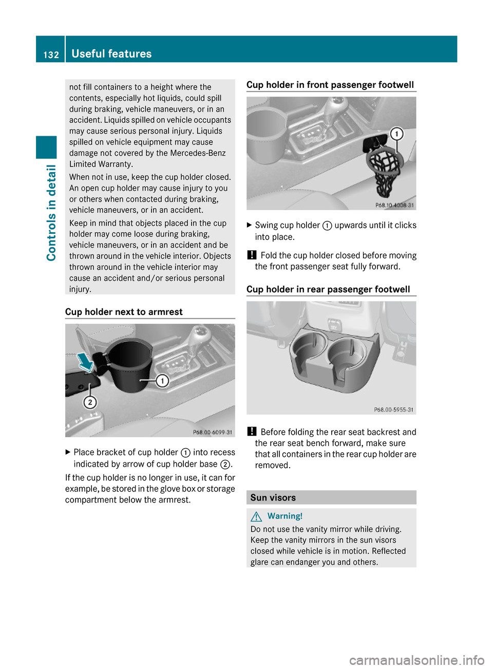
Cup holder in front passenger footwellXSwing cup holder : upwards until it clicks
into place.
! Fold the cup holder closed before moving
the front passenger seat fully forward.
Cup holder in rear passenger footwell
! Before folding the rear seat backrest and
the rear seat bench forward, make sure
that all containers in the rear cup holder are
removed.
Sun visors
GWarning!
Do not use the vanity mirror while driving.
Keep the vanity mirrors in the sun visors
closed while vehicle is in motion. Reflected
glare can endanger you and others.
132Useful featuresControls in detail
463_AKB; 2; 52, en-USd2ureepe,Version: 2.11.7.12008-12-02T10:52:11+01:00 - Seite 132
Page 135 of 264
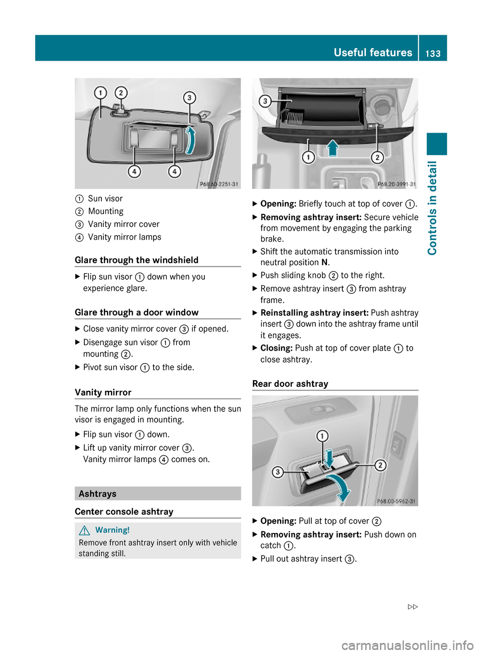
:Sun visor;Mounting=Vanity mirror cover?Vanity mirror lamps
Glare through the windshield
XFlip sun visor : down when you
experience glare.
Glare through a door window
XClose vanity mirror cover = if opened.XDisengage sun visor : from
mounting ;.
XPivot sun visor : to the side.
Vanity mirror
The mirror lamp only functions when the sun
visor is engaged in mounting.
XFlip sun visor : down.XLift up vanity mirror cover =.
Vanity mirror lamps ? comes on.
Ashtrays
Center console ashtray
GWarning!
Remove front ashtray insert only with vehicle
standing still.
XOpening: Briefly touch at top of cover :.XRemoving ashtray insert: Secure vehicle
from movement by engaging the parking
brake.
XShift the automatic transmission into
neutral position N.
XPush sliding knob ; to the right.XRemove ashtray insert = from ashtray
frame.
XReinstalling ashtray insert: Push ashtray
insert = down into the ashtray frame until
it engages.
XClosing: Push at top of cover plate : to
close ashtray.
Rear door ashtray
XOpening: Pull at top of cover ;XRemoving ashtray insert: Push down on
catch :.
XPull out ashtray insert =.Useful features133Controls in detail463_AKB; 2; 52, en-USd2ureepe,Version: 2.11.7.12008-12-02T10:52:11+01:00 - Seite 133Z
Page 136 of 264
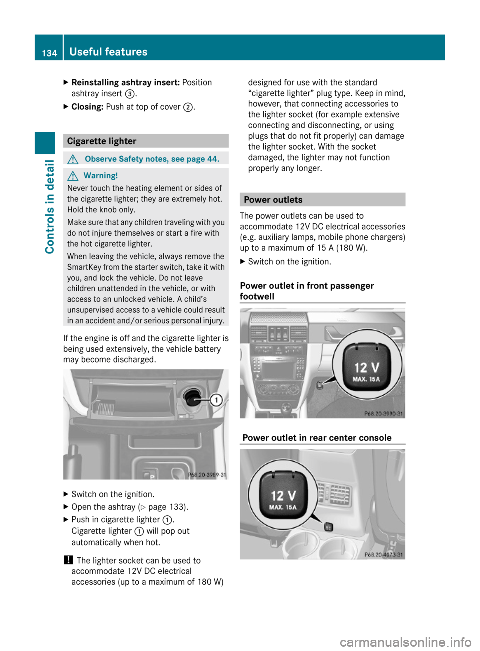
XReinstalling ashtray insert: Position
ashtray insert =.
XClosing: Push at top of cover ;.
Cigarette lighter
GObserve Safety notes, see page 44.GWarning!
Never touch the heating element or sides of
the cigarette lighter; they are extremely hot.
Hold the knob only.
Make sure that any children traveling with you
do not injure themselves or start a fire with
the hot cigarette lighter.
When leaving the vehicle, always remove the
SmartKey from the starter switch, take it with
you, and lock the vehicle. Do not leave
children unattended in the vehicle, or with
access to an unlocked vehicle. A child’s
unsupervised access to a vehicle could result
in an accident and/or serious personal injury.
If the engine is off and the cigarette lighter is
being used extensively, the vehicle battery
may become discharged.
XSwitch on the ignition.XOpen the ashtray (Y page 133).XPush in cigarette lighter :.
Cigarette lighter : will pop out
automatically when hot.
! The lighter socket can be used to
accommodate 12V DC electrical
accessories (up to a maximum of 180 W)
designed for use with the standard
“cigarette lighter” plug type. Keep in mind,
however, that connecting accessories to
the lighter socket (for example extensive
connecting and disconnecting, or using
plugs that do not fit properly) can damage
the lighter socket. With the socket
damaged, the lighter may not function
properly any longer.
Power outlets
The power outlets can be used to
accommodate 12V DC electrical accessories
(e.g. auxiliary lamps, mobile phone chargers)
up to a maximum of 15 A (180 W).
XSwitch on the ignition.
Power outlet in front passenger
footwell
Power outlet in rear center console
134Useful featuresControls in detail
463_AKB; 2; 52, en-USd2ureepe,Version: 2.11.7.12008-12-02T10:52:11+01:00 - Seite 134
Page 137 of 264
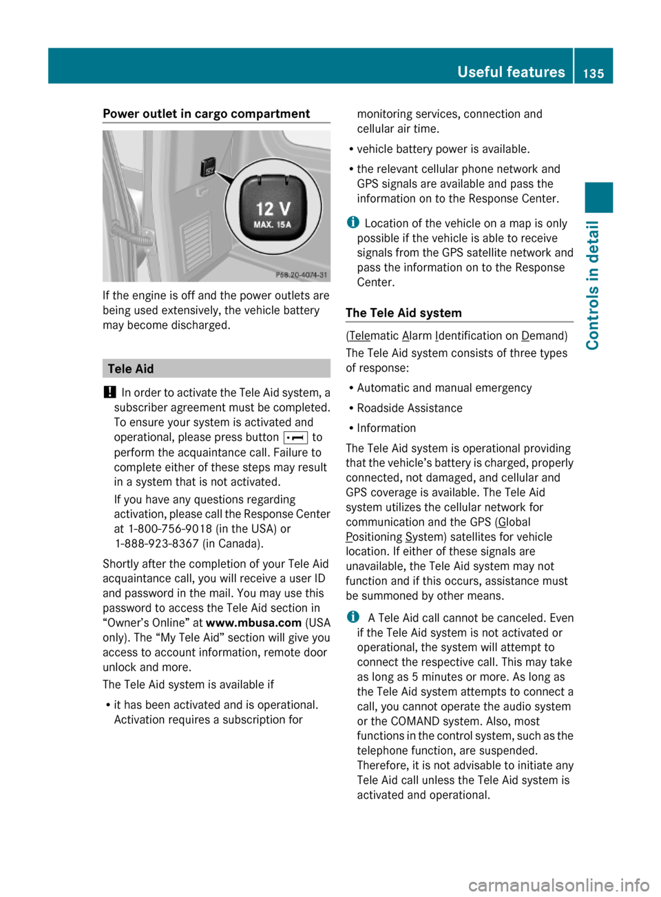
Power outlet in cargo compartment
If the engine is off and the power outlets are
being used extensively, the vehicle battery
may become discharged.
Tele Aid
! In order to activate the Tele Aid system, a
subscriber agreement must be completed.
To ensure your system is activated and
operational, please press button E to
perform the acquaintance call. Failure to
complete either of these steps may result
in a system that is not activated.
If you have any questions regarding
activation, please call the Response Center
at 1-800-756-9018 (in the USA) or
1-888-923-8367 (in Canada).
Shortly after the completion of your Tele Aid
acquaintance call, you will receive a user ID
and password in the mail. You may use this
password to access the Tele Aid section in
“Owner’s Online” at www.mbusa.com (USA
only). The “My Tele Aid” section will give you
access to account information, remote door
unlock and more.
The Tele Aid system is available if
Rit has been activated and is operational.
Activation requires a subscription for
monitoring services, connection and
cellular air time.
Rvehicle battery power is available.
Rthe relevant cellular phone network and
GPS signals are available and pass the
information on to the Response Center.
iLocation of the vehicle on a map is only
possible if the vehicle is able to receive
signals from the GPS satellite network and
pass the information on to the Response
Center.
The Tele Aid system
(Telematic Alarm Identification on Demand)
The Tele Aid system consists of three types
of response:
RAutomatic and manual emergency
RRoadside Assistance
RInformation
The Tele Aid system is operational providing
that the vehicle’s battery is charged, properly
connected, not damaged, and cellular and
GPS coverage is available. The Tele Aid
system utilizes the cellular network for
communication and the GPS (Global
Positioning System) satellites for vehicle
location. If either of these signals are
unavailable, the Tele Aid system may not
function and if this occurs, assistance must
be summoned by other means.
i A Tele Aid call cannot be canceled. Even
if the Tele Aid system is not activated or
operational, the system will attempt to
connect the respective call. This may take
as long as 5 minutes or more. As long as
the Tele Aid system attempts to connect a
call, you cannot operate the audio system
or the COMAND system. Also, most
functions in the control system, such as the
telephone function, are suspended.
Therefore, it is not advisable to initiate any
Tele Aid call unless the Tele Aid system is
activated and operational.
Useful features135Controls in detail463_AKB; 2; 52, en-USd2ureepe,Version: 2.11.7.12008-12-02T10:52:11+01:00 - Seite 135Z
Page 138 of 264
Page 139 of 264
GWarning!
If the indicator lamp in the SOS button is
flashing continuously and there was no voice
connection to the Response Center
established, then the Tele Aid system could
not initiate an emergency call (e.g. the
relevant cellular phone network is not
available).
The message Call Failed appears in the
multifunction display for approximately
10 seconds.
Should this occur, assistance must be
summoned by other means.
iThe “911” emergency call system is a
public service. Using it without due cause
is a criminal offense.
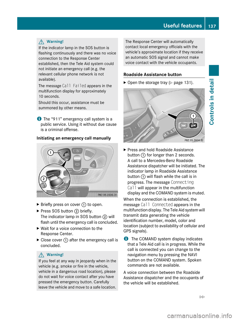
Initiating an emergency call manually
XBriefly press on cover : to open.XPress SOS button ; briefly.
The indicator lamp in SOS button ; will
flash until the emergency call is concluded.
XWait for a voice connection to the
Response Center.
XClose cover : after the emergency call is
concluded.
GWarning!
If you feel at any way in jeopardy when in the
vehicle (e.g. smoke or fire in the vehicle,
vehicle in a dangerous road location), please
do not wait for voice contact after you have
pressed the emergency button. Carefully
leave the vehicle and move to a safe location.
The Response Center will automatically
contact local emergency officials with the
vehicle’s approximate location if they receive
an automatic SOS signal and cannot make
voice contact with the vehicle occupants.
Roadside Assistance button
XOpen the storage tray (Y page 131).XPress and hold Roadside Assistance
button : for longer than 2 seconds.
A call to a Mercedes-Benz Roadside
Assistance dispatcher will be initiated. The
indicator lamp in Roadside Assistance
button : will flash while the call is in
progress. The message Connecting
Call will appear in the multifunction
display and the COMAND system is muted.
When the connection is established, the
message Call Connected appears in the
multifunction display. The Tele Aid system will
transmit data generating the vehicle
identification number, model, color and
location (subject to availability of cellular and
GPS signals).
i The COMAND system display indicates
that a Tele Aid call is in progress. While the
call is connected you can change to the
navigation menu by pressing the NAVI
button on the COMAND system. Spoken
commands are not available.
A voice connection between the Roadside
Assistance dispatcher and the occupants of
the vehicle will be established.
Useful features137Controls in detail463_AKB; 2; 52, en-USd2ureepe,Version: 2.11.7.12008-12-02T10:52:11+01:00 - Seite 137Z
Page 140 of 264
XDescribe the nature of the need for
assistance.
The Mercedes-Benz Roadside Assistance
dispatcher will either dispatch a qualified
Mercedes-Benz technician or arrange to tow
your vehicle to the nearest authorized
Mercedes-Benz Center. For services such as
labor and/or towing, charges may apply.
Refer to the Roadside Assistance manual for
more information.
Sign and Drive services (USA:only):
Services such as a jump start, a few gallons
of fuel or the replacement of a flat tire with
the vehicle spare tire are obtainable at no
charge.
iIf the indicator lamp in Roadside
Assistance button : is flashing
continuously and there was no voice
connection to the Response Center
established, then the Tele Aid system could
not initiate a Roadside Assistance call (e.g.
the relevant cellular phone network is not
available). The message Call Failed
appears in the multifunction display.
XTerminating calls: Press button ~ on
the multifunction steering wheel.
or
XPress the respective button for ending a
telephone call on the COMAND system.
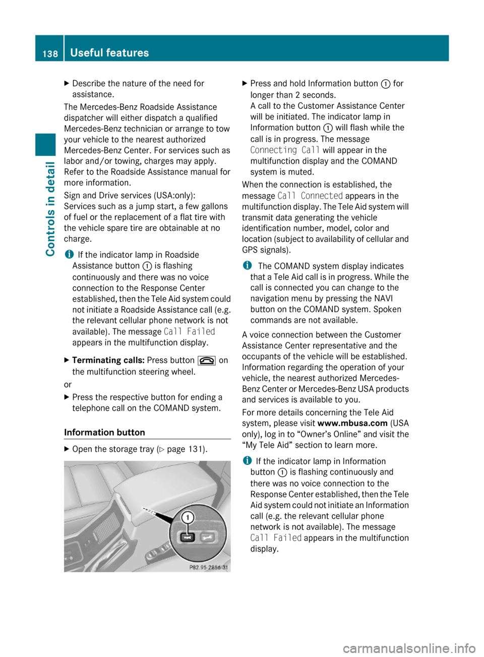
Information button
XOpen the storage tray (Y page 131).XPress and hold Information button : for
longer than 2 seconds.
A call to the Customer Assistance Center
will be initiated. The indicator lamp in
Information button : will flash while the
call is in progress. The message
Connecting Call will appear in the
multifunction display and the COMAND
system is muted.
When the connection is established, the
message Call Connected appears in the
multifunction display. The Tele Aid system will
transmit data generating the vehicle
identification number, model, color and
location (subject to availability of cellular and
GPS signals).
i The COMAND system display indicates
that a Tele Aid call is in progress. While the
call is connected you can change to the
navigation menu by pressing the NAVI
button on the COMAND system. Spoken
commands are not available.
A voice connection between the Customer
Assistance Center representative and the
occupants of the vehicle will be established.
Information regarding the operation of your
vehicle, the nearest authorized Mercedes-
Benz Center or Mercedes-Benz USA products
and services is available to you.
For more details concerning the Tele Aid
system, please visit www.mbusa.com (USA
only), log in to “Owner’s Online” and visit the
“My Tele Aid” section to learn more.
iIf the indicator lamp in Information
button : is flashing continuously and
there was no voice connection to the
Response Center established, then the Tele
Aid system could not initiate an Information
call (e.g. the relevant cellular phone
network is not available). The message
Call Failed appears in the multifunction
display.
138Useful featuresControls in detail
463_AKB; 2; 52, en-USd2ureepe,Version: 2.11.7.12008-12-02T10:52:11+01:00 - Seite 138